한국표면공학회지 J. Korean Inst. Surf. Eng.
Vol. 50, No. 5, 2017.
https://doi.org/10.5695/JKISE.2017.50.5.308
<연구논문>
ISSN 1225-8024(Print) ISSN 2288-8403(Online)
Effect of NaOH Concentration on the PEO Film Formation of AZ31 Magnesium Alloy in the Electrolyte Containing Carbonate
and Silicate Ions
Sungmo Moon
a,b,*, Yeajin Kim
a,c, and Cheolnam Yang
aaSurface Technology Division, Korea Institute of Materials Science, Gyeongnam 51508, Republic of Korea
bAdvanced Materials Engineering, Korea University of Science and Technology, Daejeon 34113, Republic of Korea
cDepartment of Materials Science and Engineering, Pusan National University, Pusan 46241, Republic of Korea
(Received October 9, 2017 ; revised October 16, 2017 ; accepted October 16, 2017)
Abstract
Anodic film formation behavior of AZ31 Mg alloy was studied as a function of NaOH concentration in 1 M Na2CO3 + 0.5 M Na2SiO3 solution under the application of a constant anodic current density, based on the analyses of voltage-time curves, surface appearances and morphologies of the anodically formed PEO (plasma electrolytic oxidation) films. The anodic film formation voltage and its fluctuations became largely lowered with increasing added NaOH concentration in the solution. Two different types of film defects, large size dark spots indented from the original surface and locally extruded white spots, were observed on the PEO-treated surface, depending on the concentration of added NaOH. The large size dark spots appeared only when added NaOH concentration is less than 0.2 M and they seem to result from the local detachments of porous PEO films. The white spots were observed to be very porous and locally extruded and their size became smaller with increasing added NaOH concentration. The white spot defects disappeared completely when more than 0.8 M NaOH is added in the solution. Concludingly it is suggested that the presence of enough concentration of OH- ions in the carbonate and silicate ion-containing electrolyte can prevent local thickening and/or detachment of the PEO films on the AZ31 Mg alloy surface and lower the PEO film formation voltage less than 70 V.
Keywords : Anodic oxide film, AZ31 Mg alloy, Plasma electrolytic oxidation, Film defect
1. Introduction
Magnesium alloys have been developed for industrial uses in automobile, airplane and mobile cases because of their low density of 1.7 g/cm3. For widespread use of Mg alloys, their corrosion resistances should be improved as much as that of anodized aluminium components. Corrosion of Mg alloys is mainly due to the fact that the surface films
on Mg alloys are not so protective because of the presence of a number of imperfections in the surface oxide films. Thus, it is essential to form a protective layer by surface treatment to render improved corrosion resistance of Mg alloys.
The protective surface layer can be provided spontaneously by chemical reaction with gaseous oxygen in air, which is called as a passive film as can be seen on Ti and stainless steels, or it can be produced artificially by immersing the metal components in a specific chemical solution or by the application of anodic current, which are called as chemical conversion coating and anodic oxidation method, respectively. Chemical conversion coatings
*
Corresponding Author:Sungmo MoonSurface Technology Division, Korea Institute of Materials Science
Tel: +82-55-280-3549 ; Fax: +82-55-280-3570 E-mail: [email protected]
on Mg alloys are normally combined with E-paint to improve their corrosion resistances [1-5]. Plasma electrolytic oxidation (PEO) coatings are one of very promising surface treatment methods which can give not only very improved corrosion resistance but also excellent abrasion resistance. The PEO coatings have been widely investigated by many authors to understand their formation mechanism, morphological and structural characteristics and corrosion protective property [6-17]. The PEO method is based on the dielectric breakdown of an anodic oxide film which induces instantaneous generation of micro-arcs and then formation of new oxide film at the same site.
Since the PEO film is formed at high temperature during micro-arc generation, it becomes very hard due to its crystallization. Thus, the PEO film can be used for components which need good abrasive resistance.
For practical applications, the PEO films should have good corrosion resistance and low process cost.
Corrosion resistance of the PEO-treated metal depends on the film thickness and the presence of imperfections in the film. The process cost of PEO method is closely related with process time, applied current density and film formation voltage. Electrical power consumed for the PEO film formation is proportional to the applied current and voltage. Thus, if a constant applied current density is used, the PEO film formation voltage should be lowered as much as possible to reduce the electrical power used. The PEO film formation voltage was reported to be normally more than 400 V [18-20] and some papers have reported much lowered PEO film formation voltages of 300 V [21,22] and 150 V [23]. The PEO film formation voltage of AZ31 Mg alloy was reported to depend on the concentration of ions in the electrolyte. OH- ions were reported also to act as an film breakdown agent which reduces the PEO film formation voltage in SiO32- ion-containing electrolytes [12] and in an electrolyte containing PO43- and SiO32- ions [16]. However, at present, effect of OH- ions combined with CO32- and SiO32- ions on the PEO film formation behavior on AZ31 Mg alloy is not still clear.
In this work, anodic oxidation behavior of AZ31 Mg alloy was studied as a function of NaOH concentration in electrolyte containing carbonate and silicate ions by analysing voltage-time curves, surface appearance and morphologies of the PEO films formed at galvanostatic condition, in view of formation and detachment of PEO films and changes in the PEO film formation voltage.
2. Experimental
AZ31 Mg alloy plate (wt.%, Al 2.94, Zn 0.8, Mn 0.3, Si < 0.1, Fe < 0.005, Cu < 0.05, Ni < 0.005 and Mg balance) of 1 mm thickness was cut and abraded into 10 mm wide and 70 mm long specimen using SiC papers. The specimen surface was abraded finally by a blade to expose very fresh and smooth surface for improved adhesion with a masking tape, according to the same specimen preparation method reported in a previous paper [24]. The exposed area of the specimen was controlled to be 10 cm2. The masked specimen was directly used for plasma electrolytic oxidation (PEO) experiments without any chemical pre-treatment. The electrolyte used for the PEO experiments was 1 M Na2CO3 + 0.5 M Na2SiO3 solution containing various concentration of NaOH up to 1.4 M. The PEO treatments were conducted by the application of a direct current density of 160 mA/cm2 and the electrolyte temperature was kept to be lower than 30oC using a water bath throughout the PEO experiment. Digital photographs of the specimen surface were taken after the PEO treatment. The PEO-treated Al1050 alloy surfaces were observed by 3-D digital optical microscope (Hirox) and SEM (JSM-6610LV). Cross-sectional morphologies of the PEO films formed on Al1050 alloy were also observed by the optical microscope.
3. Results and discussion
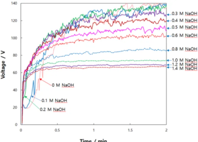
Figure 1 presents voltage-time curves of AZ31 Mg alloy obtained during the plasma electrolytic oxidation at constant current condition in 1 M Na2CO3 + 0.5 M Na2SiO3 solution containing various NaOH concentrations. In the carbonate and silicate containing solution, the anodic film formation voltage of AZ31 Mg alloy increased rapidly upon the application of the anodic current and reached steady- state values, irrespective of the amount of NaOH added. Interestingly, sudden drop and recovery of anodic film formation voltage in the initial stage appeared only when the amount of NaOH is less than 0.2 M in the carbonate and silicate containing solution. With increasing amount of added NaOH more than 0.2 M into the 1 M Na2CO3 + 0.5 M Na2SiO3 solution, the anodic film formation voltage increased more rapidly in the initial stage within 10 s and reached lowered steady-state values. Large voltage fluctuations at the steady-state were observed when concentration of NaOH is less than 0.5 M and
the voltage fluctuations disappeared completely when concentration of NaOH is more than 1 M in 1 M Na2CO3 + 0.5 M Na2SiO3 solution.
Dependence of PEO (plasma electrolytic oxidation) film formation voltage on NaOH concentration added into 1 M Na2CO3 + 0.5 M Na2SiO3 solution, is exhibited in Fig. 2. The steady-state value of PEO film formation voltage decreased rapidly when added NaOH concentration is more than 0.4 M, as indicated by blue arrows, and linear decrease with a slope of - 0.5 was obtained in the logarithmic plot of Fig. 2(b).
It is noted that the PEO film formation voltage of AZ31 Mg alloy decreases most rapidly with increasing added NaOH concentration around 0.5 M and it showed about 67 V at 1.4 M of added NaOH in 1 M Na2CO3 + 0.5 M Na2SiO3 solution. The reason for the lowered PEO film formation voltage by adding high NaOH concentration can be attributed to the easy breakdown of the oxide film which results from higher joule heating by large migration
of OH- ions through the anodic films.
In order to reduce the electrical energy used for PEO film formation, lowering the PEO film formation voltage is essential. PEO film formation voltage has been reported to be normally more than 400 V [18- 20] and some papers have reported much lowered PEO film formation voltages of 300 V [21,22] and 150 V [23]. The extremely lowered PEO film formation voltage less than 70 V obtained in this work can lead to a very cost-effective PEO process.
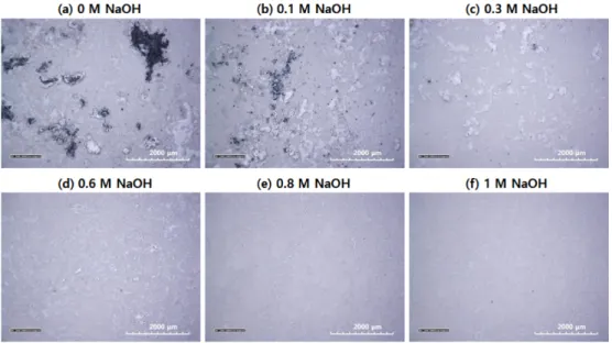
In order to use PEO films for practical applications, the PEO films should have uniform surface morphology without any pits, trenches or burned spots. Figure 3 shows typical surface appearances obtained at different NaOH concentrations in 1 M Na2CO3 + 0.5 M Na2SiO3 solution. Large size dark spots and burned spots were observed on the PEO-treated surface when the amount of NaOH added is lower than 0.2 M. and large size white spots were observed when the amount of NaOH added is between 0.2 M and 0.5 M. It should be pointed out that large size white spots disappeared if more than 0.5 M NaOH is added in M Na2CO3 + 0.5 M Na2SiO3 solution where film formation voltage decreases most rapidly with increasing added NaOH concentration, as depicted in Fig. 2.
Surface morphologies of the PEO-treated AZ31 Mg alloy in 1 M Na2CO3 + 0.5 M Na2SiO3 solution containing various NaOH concentrations were observed by optical microscope and the results are given in Fig 4. Large size dark spots and white spots were observed on the PEO-treated AZ31 Mg alloy surface when there is no addition of NaOH in 1 M Na2CO3 + 0.5 M Na2SiO3 solution. The size of white spots became smaller with increasing NaOH concentration in the electrolyte and they disappeared Fig. 1. Voltage-time curves of AZ31 Mg alloy obtained
at 160 mA/cm2 in 1 M Na2CO3 + 0.5 M Na2SiO3 solution containing various NaOH concentrations.
Fig. 2. Plots of steady-state film formation voltages of AZ31 Mg alloy with NaOH concentration added in 1M Na2CO3+ 0.5M Na2SiO3 solution in (a) linear and (b) logarithmic scales.
completely when more than 0.8 M NaOH is added, showing uniform surface morphology of the PEO films, as can be seen in Fig. 4. Thus, it can be said that white defects on the PEO-treated AZ31 Mg alloy surface are not be formed in 1 M Na2CO3 + 0.5 M Na2SiO3 solution containing more than 0.8 M NaOH.
Figure 5 shows typical large size defects found on the surface of AZ31 Mg alloy after PEO treatment in 1 M Na2CO3 + 0.5M Na2SiO3 solution without addition of NaOH. Large size dark defects, indicated by numbers of 5 and 7 in Figs (b) and (d), were observed to be indented, as shown clearly in Figs.
5(c) and 5(e). In contrast, white defects, indicated by numbers of 1, 2, 3, 4 and 6, were found to be more extruded than the other surface. The black spots and white defects are attributed to the results of
detachment and growth of porous PEO films, respectively. Considering that the dark spots and white defects disappear if NaOH is added sufficiently into 1 M Na2CO3 + 0.5M Na2SiO3 solution, it is readily inferred that the presence of high concentration of OH- ions in the solution containing carbonate and silicate ions can prevent local thickening and detachment of porous PEO films on the AZ31 Mg alloy surface.
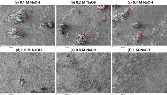
Figure 6 demonstrates SEM images of white defects observed in Figs. 3 and 4 on the PEO-treated surface of AZ31 Mg alloy in 0.1 M in 1M Na2CO3 + 0.5M Na2SiO3 solution containing various NaOH concentrations. Local thickening of PEO films were found, as indicated by red arrows, and their number and size decreased with increasing NaOH concentration Fig. 3. Digital photographs of the PEO-treated AZ31 Mg alloy for 2 min at 160 mA/cm2 in 1 M Na2CO3 + 0.5 M Na2SiO3 solution containing various concentrations of NaOH.
Fig. 4. Optical microscope images of the PEO-treated AZ31 Mg alloy surface for 2 min at 160 mA/cm2 in 1M Na2CO3 + 0.5M Na2SiO3 solution containing various concentrations of NaOH.
in the carbonate and silicate containing electrolyte. It is clear that the PEO films formed on AZ31 Mg alloy become more uniform with less local defects with increasing NaOH concentration in the electrolyte. It is also noticed that small size local defects were observed up to 0. 8 M NaOH concentration in the carbonate and silicate containing electrolyte.
Locally thickened PEO films and intended surface due to detachment of the PEO films, were clearly observed by optical microscope from the cross-
sections, as indicated by red arrows in Fig. 7. Locally thickened PEO films show highly extruded shape from the original surface, comparing with the intended depth of the consumed substrate, indicating that more electrolyte components are trapped in the PEO films than the metal cations provided by anodic reaction The reason why such local thickening of PEO films is prevented by adding NaOH, is attributed to more enhanced formation of Mg(OH)2 by which more uniform and denser PEO films may be formed.
Fig. 5. Two-dimensional (a, b, d) and three-dimensional (c, e) optical microscope images of the PEO-treated AZ31 M surface for 2 min at 160 mA/cm2 in 1M Na2CO3 + 0.5M Na2SiO3 solution.
Fig. 6. SEM images of the PEO-treated AZ31 Mg alloy surface for 2 min at 160 mA/cm2 in 1M Na2CO3 + 0.5M Na2SiO3 solution containing various concentrations of NaOH.
4. Conclusions
Anodic oxidation behavior of AZ31 Mg alloy in 1 M Na2CO3 + 0.5 M Na2SiO3 solution containing various Na2CO3 concentrations was studied by anodic voltage-time curves and observation of surface appearance and morphologies of the anodically treated sample. The anodic voltage showed initial rapid increase and then reached at a steady-state. Sudden drop and recovery of the anodic voltage in the initial stage appeared only when the amount of NaOH is less than 0.2 M and large voltage fluctuations at the steady-state were observed when the added amount of NaOH is less than 0.5 M.
The voltage fluctuations disappeared completely when the amount of NaOH is more than about 1 M where relatively uniform PEO films were formed.
The PEO film formation voltage at the steady-state became lowered down to about 67 V by adding 1.4 M NaOH, so that electricity consumed for the preparation of PEO films is significantly lowered.
Two different types of defects, large size dark spots and various sizes of white spots, were observed in the PEO film formed on AZ31 Mg alloy in the carbonate and silicate containing solution, depending on the concentration of added NaOH. The large size dark spots were found to be indented from the original surface and appeared only when added NaOH concentration is less than 0.2 M and they seem to result from the local detachments of porous PEO films. The white defects were observed to be very porous and locally extruded, comparing with the
other surface without defects, and they become smaller in size with increasing added NaOH concentration. The white defects disappeared completely when more than 0.8 M NaOH is added in the electrolyte. Based on the experimental results obtained in this work, it is concluded that the presence of enough concentration of OH- ions in the solution containing carbonate and silicate ions can prevent local thickening and/or detachment of the PEO films on the AZ31 Mg alloy surface and lowers the PEO film formation voltage less than 70 V.
Acknowledgement
This research was financially supported by a research grant from the The National Research Council of Science & Technology (POC2600).
References
[1] Nguyen Van Phuong, Sungmo Moon, “The effects of surface pre-treatment methods on the structure and corrosion resistance of zinc phosphate conversion coatings on AZ31 Mg alloy”, Science of Advanced Materials, 6 (2014) 1-7.
[2] Nguyen Van Phuong, Sungmo Moon, “Comparative corrosion study of zinc phosphate and magnesium phosphate conversion coatings on AZ31 Mg alloy”, Materials Letters, 122 (2014) 341–344.
[3] Nguyen Van Phuong, Sungmo Moon, “Deposition and characterization of E-paint on magnesium alloys”, Progress in Organic Coatings 89 (2015) 91-99.
[4] Basit Raza Fazal, Sungmo Moon, “Formation of Cerium Conversion Coatings on AZ31 Magnesium Alloy”, J. Kor. Inst. Surf. Eng., 49 (2016) 1-13.
[5] Nguyen Van Phuong, Sungmo Moon, “Deposition and Characterization of Electrophoretic Paint on AZ31 Magnesium”, J. Kor. Inst. Surf. Eng., 49 (2016) 141-146.
[6] J. Liang, B. Guo, J. Tian, H. Liu, J. Zhou, T.
Xu, Effect of potassium fluoride in electrolytic solution on the structure and properties of microarc oxidation coatings on magnesium alloy, Applied Surface Science. 252 (2005) 345-351.
[7] H. Duan, C. Yan, F. Wang, Effect of electrolyte additives on performance of plasma electrolytic oxidation films formed on magnesium alloy AZ91D, Electrochimica Acta. 52 (2007), 3785- 3793.
[8] L. Chai, X. Yu, Z. Yang, Y. Wang, Masazumi Okido, Anodizing of magnesium alloy AZ31 in Fig. 7. Cross-sectional images of PEO-treated AZ31 Mg
alloy for 2 min at 160 mA/cm2 in 1M Na2CO3 + 0.5M Na2SiO3 solution containing various NaOH concentrations of (a) 0 M, (b) 0.1 M, (c) 0.2 M, (d) 0.3 M and (e) 0.4 M.
alkaline solutions with silicate under continuous sparking, Corros. Sci., 50 (2008) 3274.
[9] S. Moon, Y. Nam, Anodic oxidation of Mg-Sn alloys in alkaline solutions, Corrosion Science 65 (2012) 494-501.
[10] T. S. Lim, H. S. Ryu, S. -H. Hong, Electrochemical corrosion properties of CeO2-containing coatings on AZ31 magnesium alloys prepared by plasma electrolytic oxidation, Corros. Sci. 62 (2012) 104.
[11] S. Moon, Corrosion behavior of PEO-treated AZ31 Mg alloy in chloride solution, Journal of Solid State Electrochemistry. 18 (2014) 341-346.
[12] S. Moon, C. Yang, S. Na, Effects of Hydroxide and Silicate ions on the Plasma Electrolytic Oxidation of AZ31 Mg Alloy, Kor. Inst. Surf.
Eng. 47(2014) 147-154.
[13] Stojadinović, Stevan, et al., Characterization of plasma electrolytic oxidation of magnesium alloy AZ31 in alkaline solution containing fluoride, Surface and Coatings Technology 273 (2015) 1-11.
[14] X. Lu, C Blawert, Y. Huang, H Ovri, M. L.
Zheludkevich, K. U. Kainer, Plasma electrolytic oxidation coatings on Mg alloy with addition of SiO2 particles, Electrochimica Acta 187 (2016) 20-33.
[15] S. Moon, R. Arrabal, E. Matykina, 3-Dimensional structures of open-pores in PEO films on AZ31 Mg alloy, Materials Letters 161 (2016) 439-441.
[16] D. Kwon, S. Moon, Effects of NaOH Concentration on the Structure of PEO Films Formed on AZ31 Mg Alloy in PO43− and SiO32− Containing Aqueous Solution, Kor. Inst. Surf. Eng. 49 (2016) 46-53.
[17] Sungmo Moon, Duyoung Kwon, Anodic Oxide Films Formed on AZ31 Magnesium Alloy by Plasma Electrolytic Oxidation Method in Electrolytes Containing Various NaF Concentrations, Kor. Inst. Surf. Eng. 49 (2016) 225-230.
[18] Li Wang, Li Chen, Zongcheng Yan, Honglin Wang, Jiazhi Peng, The influence of additives on the stability behavior of electrolyte, discharges and PEO films characteristics, Journal of Alloys and Compounds 493 (2010) 445-452.
[19] A. Madhan Kumar, Sun Hwan Kwon, Hwa Chul Jung, Kwang Seon Shin, Corrosion protection performance of single and dual Plasma Electrolytic Oxidation (PEO) coating for aerospace applications, Materials Chemistry and Physics 149–
150 (2015) 480-486.
[20] Hariprasad S., Gowtham S., Arun S., Ashok M., Rameshbabu N., Fabrication of duplex coatings on biodegradable AZ31 magnesium alloy by integrating cerium conversion (CC) and plasma electrolytic oxidation (PEO) processes, Journal of Alloys and Compounds 722 (2017) 698-715.
[21] Li Wang, Li Chen, Zongcheng Yan,Honglin Wang, Jiazhi Peng, Effect of potassium fluoride on structure and corrosion resistance of plasma electrolytic oxidation films formed on AZ31 magnesium alloy, Journal of Alloys and Compounds 480 (2009) 469-474.
[22] M. Toorani, M. Aliofkhazraei, M. Golabadi, A.
Sabour Rouhaghdam, Effect of lanthanum nitrate on the microstructure and electrochemical behavior of PEO coatings on AZ31 Mg alloy, Journal of Alloys and Compounds 719 (2017) 242-255.
[23] Sachiko Ono, Shuichi Moronuki, Yoichi Mori, Akihiko Koshi, Hidetaka Asoh, Effect of Electrolyte Concentration on the Structure and Corrosion Resistance of Anodic Films Formed on Magnesium through Plasma Electrolytic Oxidation, Electrochimica Acta 240 (2017) 415-423.
[24] S. Moon, A Blade-Abrading Method for Surface Pretreatment of Mg Alloys, Kor. Inst. Surf. Eng.
48 (2015) 194-198.