Kor. J. Mater. Res.
Vol. 23, No. 9 (2013)
531
Residual Stress on Concentric Laminated Fibrous Al
2O
3-ZrO
2Composites on Prolonged High Temperature Exposure
Swapan Kumar Sarkar and Byong Taek Lee †
Biomedical Engineering and Materials Department, School of Medicine, Institute of Tissue Regeneration, Soonchunhyang University 366-1, Sangyoung-dong, Cheonan City 330-090, Korea
(Received July 2, 2013 : Received in revised form July 2, 2013 : Accepted July 29, 2013)
Abstract
This paper investigates the effect of prolonged high temperature exposure on concentric laminated Al2O3-ZrO2 composites. An ultrafine scale microstructure with a cellular 7 layer concentric lamination with unidirectional alignment was fabricated by a multi-pass extrusion method. Each laminate in the microstructure was 2-3µm thick. An alternate lamina was
composed of 75%Al2O3-(25%m-ZrO2) and t-ZrO2 ceramics. The composite was sintered at 1500oC and subjected to 1450oC temperature for 24 hours to 72 hours. We investigated the effect of long time high temperature exposure on the generation of residual stress and grain growth and their effect on the overall stability of the composites. The residual stress development and its subsequent effect on the microstructure with the edge cracking behavior mechanism were investigated. The residual stress in the concentric laminated microstructure causes extensive micro cracks in the t-ZrO2 layer, despite the very thin laminate thickness. The material properties like Vickers hardness and fracture toughness were measured and evaluated along with the microstructure of the composites with prolonged high temperature exposure.Key words
laminated composites, residual stress, multi-pass extrusion, micro-structure, alumina, zirconia.1. Introduction
Al
2O
3-ZrO
2ceramics have been used extensively as an industrial material because of their excellent chemical and thermal stability, hardness and wear resistance pro- perties.
1,2)In case of high temperature structural application an important concern is the mechanical stability of the ceramics. However, Al
2O
3exhibits low fracture toughness, which limits its usability. Many efforts have been made to improve the mechanical properties of ceramics like the exploitation of the reinforcing action of grain anisotropy, the promotion of the crack shielding effects, phase- transformation or micro-cracking to attain higher fracture toughness.
3)The advancement on crack-shielding mechanism using microstructure related features with many new microstructure designs has made significant progress in recent time.
4-6)Ceramic laminates are considered for struc- tural applications to impart damage tolerance for condi- tions where cracks extend at constant strains.
7-12)Numerous studies have been conducted on the development of different aspects of the contributory effects of the laminated micro-
structure on Al
2O
3-ZrO
2composites based on different microstructure and design related features. Crack-shielding phenomena related to the presence of the layers(delam- ination, crack deflection, etc) were studied and docu- mented.
13-15)The laminated microstructure is said to induce and modify the residual stress within the alternate laminates depending on their mismatch in co-efficient of thermal expansion(CTE), extent of consolidation, elastic modulus etc during the sintering process. High compres- sive and tensile residual stresses can be built up in successive thin layers of the laminate.
16)It was reported that the residual stress development was critical for the material performance. Surface compressive residual stress was described to improve the crack resistance behavior.
Especially, the laminated phase with a higher CTE can exhibit higher tensile residual stress. Excessive residual tensile stress can potentially fail the material by inducing edge crack channeling. It was established that there is a minimum critical thickness for the planer laminated com- posites for which cracks cannot appear. High temperature creep behavior has been found to be changed in layered
†
Corresponding author
E-Mail : [email protected] (B. T. Lee, Soonchunhyang Univ.)
© Materials Research Society of Korea, All rights reserved.
This is an Open-Access article distributed under the terms of the Creative Commons Attribution Non-Commercial License (http://creative-
commons.org/licenses/by-nc/3.0) which permits unrestricted non-commercial use, distribution, and reproduction in any medium, provided the
original work is properly cited.
microstructure due to the presence of distinct and well developed interface.
17)This kind of microstructure has exhibited enhanced ductility and creep resistance. How- ever, these reports are based on planer laminated com- posites which is said to have developed anisotropic material characteristics for their microstructural design and partly due to the highly oriented patterned distribution of developed residual stress. Previously we have fabricated a concentric laminated microstructure in Al
2O
3-ZrO
2composites system which reduces the anisotropy of the design with dimensional symmetry in 2 D(normal to the plane of axis of concentric unit cell microstructure).
18)This feature can be thought to use to dwarf the anisotropic residual stress distribution during thermal residual stress development. The design has a unique feature of fabri- cating very fine laminates in the order of 2 µm. This is far bellow the critical thickness required for the edge cracking. If the material is required to withstand a prolonged high temperature exposure, these features can be of a great significance. However, apart from the di- mension, the geometric configuration of the microstruc- ture too can influence the development and pattern of residual stress. The overall effect of the thermal strain in the residual stress development grossly depends on the entire geometry and distribution of distinct phases of the specimen. At high temperature prolonged exposure the grain growth phenomena alters the microstructural features and the residual stress at grain boundary level is altered.
The laminated microstructure under this situation should undergo with associated influences. In the Al
2O
3system the high temperature grain growth is a concern for the material properties degradation especially for hardness, creep behavior, fracture toughness etc. Grain growth in high temperature environment is due to the thermal diffu- sion of the atoms or ions at grain boundary layer. Incor- poration of a second phase can restrict this successfully by separating phases and creating a barrier. In view of this, a very fine laminated microstructure with the laminate thickness in the order of the grain size and con- sequently having very fine geometric isolation between phases can successfully restrict the grain growth. We have shown in this paper that exposure at 1450
oC for 72 hours did minimal grain growth in the concentric lamin- ated composites.
This paper investigates this novel microstructure with distributed concentric laminated micro groups regarding to its stability in prolonged high temperature exposure in relation to residual stress development and its effect on the microstructure. The finite dimension of the concentric laminated micro-group had a profound effect by creating extensive edge crack channeling, which seriously hampers the stability of the composites.
2. Experimental Procedure
The starting powders used in this experiment were Al
2O
3(AKP-50, average diameter 300 nm, Sumimoto, Japan), monoclinic Zirconia(m-ZrO
2) (TZ-0Y, average diameter 80 nm, Tosoh, Japan) and tetragonal Zirconia(t- ZrO
2) (TZ-3Y, average diameter 80 nm, Tosoh, Japan).
Polymer laden ceramics powders were prepared by shear mixing as described before.
18)The polymer-laden t-ZrO
2and Al
2O
3-mZrO
2plastic materials were then extruded in a heated die separately to obtain green filaments 2 mm in diameter and 8 mm in length. These two kinds of filaments were then arranged in a cylindrical steel die of 30 mm in diameter. The t-ZrO
2filaments were arranged against the die wall making the outer layer. The next inner layer was made with the Al
2O
3-(m-ZrO
2) filaments.
Successive inner layers were made with alternate t-ZrO
2and Al
2O
3-(m-ZrO
2) filaments filling the entire die. Three layers of Al
2O
3-(m-ZrO
2) filaments were arranged sand- wiched within four t-ZrO
2filament layers. A total of 7 alternate layers of t-ZrO
2and Al
2O
3-(m-ZrO
2) filaments made up the entire arrangement. This arrangement of the alternate layers of t-ZrO
2and Al
2O
3-(m-ZrO
2) constitutes the primary microstructure of concentric multilayer. The final green composite filament was fabricated by repeated extrusion as stated earlier
18)to have 3
rdpassed filament of 3.5 mm diameter. Polymer was burnt out and sintering was done at 1450
oC for 2 hours in air. For checking the effect of high temperature exposure for extended time, samples were kept in the furnace at 1450
oC for different time periods like 24 hours, 48 hours and 72 hours.
The Vickers hardness was measured using Vickers hard- ness testing machine(HV-112, Akashi, Japan). The fracture toughness was measured by a less reliable but easy to do method named the Vickers indentation method using the Evan’s Equation.
The microstructure of the composites was examined using FE-SEM(JSM 6335F, JEOL, Tokyo, Japan).
3. Results and Discussion
Fig. 1 shows the (a) cross sectional and (b) longitu-
dinal SEM images of the 3
rdpassed multilayered Al
2O
3-
(m-ZrO
2)/t-ZrO
2sintered body. The black and the gray
contrasts are the Al
2O
3-(m-ZrO
2) and t-ZrO
2lamina, re-
spectively. The unit cell of the microstructure is clearly
shown in Fig. 1(a) which is only around 40 µm in
diameter. The individual lamina were 2~3 µm thick only
and from Fig. 1(b) it is evident that concentric lamina
extended unidirectionally throughout the composites. The
detailed microstructural analysis was presented in our
previous report.
18)The laminated composite was densified at 1500
oC tem- perature for 2 hours. The coefficient of thermal expansion (CTE) of t-ZrO
2is larger than Al
2O
3. In the composites
the separated layers of the t-ZrO
2would contract more than the Al
2O
3-(m-ZrO
2) layers during cooling. The differ- ence in the strains is given by
Fig. 1. Microstructure of the 3
rdpass composites (a) cross section image and (b) longitudinal section image.
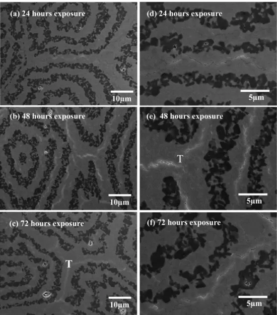
Fig. 2. Edge cracking on boundary t-ZrO
2layer viewed from cross section after exposing at 1450
oC for different duration. (a) for 24 hours
(b) for 48 hours and (c) for 72 hours. (d, e, f) are the enlarged images of (a, b, c), respectively.
ε
r= ( αZr − αAl/Zr)dT (1) where T
iand T
fare the initial and final temperatures during cooling, and αZr and αAl/Zr are the CTE's of the t-ZrO
2layer and the Al
2O
3-(m-ZrO
2) layers, respectively.
If the layers are bonded, the misfit strain (1) induces a residual tensile stress in the t-ZrO
2layer and a com- pressive residual stress in the Al
2O
3layer.
17)Practically, the development of residual stress does not start above temperature of 1000
oC ~ 1200
oC in case of Al
2O
3-ZrO
2composites due to the high temperature stress relaxation.
However, this temperature also is high enough to induce a significant extent of residual stress. The sintered sample does not undergo any kind of stress related failure. In the laminated composites it was reported that the transverse and “edge-effect” cracking are due to the in plane tensile stress and can occur only if the laminate passes a critical thickness given by the equation.
19)t
c= 4K
1C2/ πσ
R2(2)
Where, K
1Cis the fracture toughness of the layer and σ
Ris the residual stress.
In the sintered 3
rdpass composites this cracking was successfully eliminate with its fine layer thickness with almost full densification. However, due to the thinner dimension of the lamina in the 3
rdpass sample the developed residual stress is also different and is expected to be lower, which in turn make the t
chigher for this finer microstructure.
After exposing the composites for a long time in high temperature the microstructures showed cracking along the boundary t-ZrO
2layer. Each ceramic layer in the frame region was in the range of 2~3 µm in thickness, which is thinner than the conventional tape cast laminated ceramic composites. The fine tuning of the microstructure was expected to improve the performance at high tem- perature. Usually the Al
2O
3ceramics undergo significant grain growth under prolonged high temperature exposure, which may deteriorate the mechanical properties of the ceramic body. In the present composites the microstruc- tural dimension was less than 3 µm. This prohibits the grain growth of Al
2O
3within this limit in the radial direction of the unit cell at prolonged elevated tempera- ture exposure. However, the microstructure of the Al
2O
3- (m-ZrO
2) layer was sufficient to suppress any potential grain growth of Al
2O
3.
Fig. 2 shows the SEM image of the cross section of the composites after exposing at 1450
oC temperature for different time duration. The low magnification images of Fig. 2(a-c) showed that the boundary t-ZrO
2layer has edge cracks regardless of the exposure time at 1450
oC temperature. The cracks were mainly bound along the
center of the outer ZrO
2layer of the concentric micro groups or the unit cells and were traveling along with its curvature. This is contradictory to the notion that the layer thickness reduction significantly reduces the chances of edge cracking in the planer laminated composites. So the geometry of microstructure has invoked significantly dif- ferent mechanism which led to this wide spread micro- cracking. It is to be noted that the outer t-ZrO
2boundary layer thickness was almost double to that of the inner t- ZrO
2layers. The developed tensile residual stress was maximum in this area and served as the flaw initiation zone for crack initiation and propagation. The residual stress development scenario for the current microstructure was not similar with the conventional planer laminated composites. In general the lamina in the planner laminated composites have a common direction of stacking and the elastic strains of the layers are subjected to the same direction. So the residual stresses developed in stacked layers. The local strains of the laminates and the corres- ponding stresses developed are confined in the respective laminates and rarely there is any interference other than the adjacent laminates. In case of the concentric laminated microstructure it has a different structural environment.
The whole volume of the composites system contracts during the cooling time and induce a global contraction.
However, the concentric cellular micro groups experience a localized straining behavior. As the alternate concentric layers are continuous cylindrical shells they have apparently a contraction scenario that seems like they are contract- ing towards the respective central axis with in the micro- group or unit cell. In the micro-group or unit cell the strain misfit of the Al
2O
3-m-ZrO
2and t-ZrO
2layers develops alternate compressive and tensile residual stresses, respectively. The contraction of two adjacent concentric micro-groups is in opposite direction with respect to the t-ZrO
2common boundary layer. The thicker t-ZrO
2outer boundary layer is already in a tensile residual stress, higher in magnitude due to its larger dimension. These impart the thicker boundary layer to intensify the tensile residual stress. This duel effect from the layer inherent residual stress and that from geometric contribution makes the residual tensile stress of the outer t-ZrO
2layer higher than the inherent ultimate tensile strength of the layer and cracks are developed along this layer. The residual tensile stress is highest at the middle of the layer and decreases towards the layer interfaces. This is why most cracks propagate along the middle of the boundary t- ZrO
2layer. In the triple zone(marked T in Fig. 2(c, e)), were three adjacent cellular micro-groups have joined, the cracks are more prolific and intense because tensile residual stress is developed along three directions(some- times even in four due to adjacency of four micro groups with common boundary).
Ti
∫
TfThe high temperature prolonged dwelling can induce grain growth and densification(negligible though) and thereby can alter the grain boundary level residual stress.
From Fig. 2(d, e and f) it is evident that the cracks at the boundary laminate were not significantly altered with the variation of exposure time. This indicates that the grain level modification of the microstructure had a little effect on the crack generation. The strain and as a result the residual stress produced due to the geometric effect as stated earlier was much more prominent. Both from Fig.
1 and Fig. 2 it was confirmed that the layer interfaces were not smooth, rather wavy. This is because, prior to extrusion the assembled cylindrical filaments stacking were compacted by warm pressing which made a wavy interface between the filament layers. This remained throughout the repeated extrusion steps. The disruption of the planner connectivity of the layers and the relative higher extent of interface wave make the thickness to change with repeated interval within a narrow range. This translates into the residual stress variation along a single layer. This feature is supposed to pacify the cracking tendency of the tensile layer.
The longitudinal section of the Al
2O
3-(m-ZrO
2)/t-ZrO
2sintered body, subjected to 48 hours at 1450
oC tempera- tures are shown in Fig. 3. Cracks were found along the layers and interfaces of the t-ZrO
2layer. The cracks were found to be extended significantly along the interface of the layers. The unidirectional alignment of the laminate helps for this. (P) and (Q) shows the EDS profile of the laminates and shows the Al
2O
3-ZrO
2and t-ZrO
2. Although the composites were exposed at 1450
oC for as long as 72 hours, the grain growth was not significant both in
case of Al
2O
3and t-ZrO
2as shown in Fig. 4(a,b). How- ever, the as received t-ZrO
2and Al
2O
3powders were nano-metric(80 nm and 300 nm, respectively), which grows to be around 500 nm ~ 1 µm at the initial sintering cycle.
18)So the extended exposure time at 1450
oC could do a little in the grain growth. Nominal growth was observed for grains. The microstructural feature has suppressed the grain growth of the composites considerably.
From Table 1 the mechanical behavior was investigated depending on the exposure time at high temperature. The longer the exposure time was, the lower the Vickers hardness and the fracture toughness were found. This is predictable as longer exposure time means the grain grows bigger along with a degradation of the mechanical properties.
This paper described an unorthodox phenomenon of crack generation in a specific laminated microstructure with long time high temperature exposure. The findings showed that geometric orientation of the laminates have a profound effect on the residual stress generation which can ultimately fail the material. The findings could be used to make modification to such kind of microstructure that can alter the residual stress profile like designing a
Fig. 3. Edge cracking on boundary ZrO
2layer viewed from longitudinal section after exposing at 1450
oC for 48 hours. (a) low magnification SEM image, (d) high magnification SEM image. (P) and (Q) are EDS profile from the P and Q marked area of (b).
Fig. 4. Grain growth behavior of alumina and zirconia layers after exposing at 1450
oC for (a) 24 hours, (b) 48 hours and (c) 72 hours.
Table 1. mechanical properties of the composites after exposing at 1450
oC for different duration.
As sintered composites
24 hours of exposure
48 hours of exposure
72 hours of exposure Vickers
Hardness 1406 ± 59 1258 ± 25 1181 ± 10 1103 ± 16 Facture
Toughness 6.9 ± 0.69 6.8 ± 0.25 6.75 ± 0.4 6.1 ± 0.55
composite with a compressive boundary layer and a thinner tensile layer. This may help to design composites with improved mechanical characteristics.
4. Conclusion
We previously developed a cellular and fibrous micro- structure with unidirectional alignment and the unit cell comprised with a fine concentric laminated group in Al
2O
3-ZrO
2ceramic composites system. The fine alternate laminates of dissimilar phases were investigated as a phase barrier and space limiter to hinder the grain growth and to alter the residual stress distribution after prolonged high temperature application. The implication of the development of alternate tensile and compressive residual stress in the concentric laminated microstructure was in- vestigated in this work. The residual stress development was strongly influenced by the geometric configuration of the microstructure and causes extensive cracking in the composites system. Thermal effect on the type of microstructure was analyzed and suggestions were drawn for future development.
Acknowledgement
This work was supported by the Mid-career Research Program through an NRF grant funded by the MEST(NO 2009-0092808), Republic of Korea.
References
1. B. T. Lee, A. Nishiyama, K. Hiraga, Mater. Trans. JIM, 34(88), 682 (1993).
2. A. H. D. Aza, J. Chevalier, G. Fantozzi, M. Schehl, R.
Torrecillas, Biomater., 23(3), 937 (2002).
3. B. R. Lawn, Fracture of brittle solids. Cambridge University Press, London, 1993.
4. F. F. Lange, J. Am. Ceram. Soc., 72(1), 3-15 (1989).
5. A. G. Evans, J. Am. Ceram. Soc., 73(2), 187 (1990).
6. P. F. Becher, J. Am. Ceram. Soc., 74(2), 255 (1991).
7. T. Chartier, J. L. Besson and P. Boch, Mechanical Pro- perties of ZrO2-Al2O3 Laminated Composites, Advances in Ceramics: Science and Technology of Zirconia III, Vol.
24B, ed. By S. Somiya, N. Yamamoto, and H. Yanagida, The American Ceramic Society, Westerville, 1988, 1131.
8. J. Requena, R. Moreno and J. S. Moya, J. Am. Ceram.
Soc., 72(8), 1511 (1989).
9. D. B. Marshall, J. J. Ratto and F. F. Lange, J. Am. Ceram.
Soc., 74(12), 2979 (1991).
10. P. Sarkar, X. Huang and P. S. Nicholson, J. Am. Ceram.
Soc., 75(10), 2907 (1992).
11. C. J. Russo, M. P. Harmer, H. M. Chan, and G. A. Miller, J. Am. Ceram. Soc., 75(12), 3396 (1992).
12. W. A. Cutler, F. W. Zok, F. F. Lange and P. G.
Charalambides, J. Am. Ceram. Soc., 80(12), 3029 (2005).
13. D. B. Marshall, J. J. Ratto, F. F. Lange, J. Am. Ceram.
Soc., 74(12), 2979 (1991).
14. D. H. Kuo, W. M. Kriven, J. Am. Ceram. Soc., 80(9), 2421 (1997).
15. M. Oeschner, C. Hillman, F. F. Lange, J. Am. Ceram.
Soc., 79(7), 1834 (1996).
16. M. J. Melendo, F. G. Mora, A. D. Rodriguez, Acta.
Mater., 48, 4715 (2000).
17. O. N. Grigoriev, A. V. Karoteev, E. N. Maiboroda, I. L.
Berezhinsky, B. K. Serdega, D. Y. Ostrovoi, V. G.
Piskunov, Copm. Part B, 37, 530 (2006).
18. S. K. Sarkar, B. T. Lee, Ceram. Inter., 29(8), 887 (2003).
19. T. Chartier, D. Merle, J. L. Besson, J. Eur. Ceram. Soc., 15, 101 (1995).