Vol.20, No.2, (2018), pp.6~10 https://doi.org/10.9714/psac.2018.20.2.006
1. INTRODUCTION
Scale removal from feed-water is effective to recover power generation efficiency of thermal power plant. In the feed-water system, the impurity called “scale” is generated by corrosion of pipework and adheres to pipe surfaces.
Because thermal conductivity of the scale is less than 10%
of that of pipe material, removal of scale can prevent decrease in heat exchange efficiency at the boiler or feed-water heater and it leads to improvement of power generation efficiency [1]. We have developed a novel scale removal system with HGMS (High Gradient Magnetic Separation) utilizing a superconducting magnet.
As Table I shows, the composition of scale depends on water treatment methods of feed-water to prevent corrosion of pipe material. In AVT (All Volatile Treatment) and in OT (Oxygen Treatment), ferromagnetic magnetite and paramagnetic hematite are mainly generated, respectively. In this study, we focused on the removal of magnetite scale in AVT. Our final goal is to introduce this system to feed-water line of thermal power plant and to remove scale in operating plant. As a preliminary step, we considered to introduce this system to a chemical cleaning line of thermal power plant. In this paper, the feed-water line is referred as “on-line” and the chemical cleaning line is referred as “off-line”.
In our previous study, which corresponds to the fundamental study on shown in Fig.1, the design of the filter structure was examined in order to increase the.
TABLEⅠ
RELATION BETWEEN WATER TREATMENT AND FORMED SCALE.
Fig. 1. Whole picture of this study.
capture amount of magnetite. However, the filter used in the study was 50 mm in diameter, so a scale-up experiment is required for practical use of the HGMS system [2]. In this paper, we conducted a large scale mock-up experiment considering installation of HGMS system not only to on-line but also off-line system
2. DESIGNE OF PRACTICAL HGMS SYSTEM
2.1. Installation place and conditions
2.1.1. Chemical cleaning line (Off-line system)
Here, we describe the installation place of the HGMS system in off-line. Fig.2 shows the whole appearance of
AVT OT
Additive agent Ammonia, Hydrazine Oxygen, Ammonia Main substance of scale Magnetite(Fe3O4) Hematite(α-Fe2O3) Magnetic property Ferromagnetic Paramagnetic
Removal of iron scale from feed-water in thermal power plant by magnetic separation - Introduction to chemical cleaning line -
Junya Yamamotoa, Tatsuya Moria, Mami Hiramatsua, Yoko Akiyama*,a, Hidehiko Okadab, Noriyuki Hirotab, Hideki Matsuurac, Seitoku Nambac, Tomokazu Sekined, Fumihito Mishimae , and Sigehiro Nishijimae
a Osaka University, Osaka, Japan
b National Institute for Materials Science, Tsukuba, Japan
c Shikoku Research Institute Inc., Kagawa, Japan
d Ebara Industrial Cleaning Co., Ltd., Kanagawa, Japan
e Fukui University of Technology, Fukui, Japan
(Received 3 March 2018; revised or reviewed 9 May 2018; accepted 10 May 2018)
Abstract
Removal of iron oxide scale from feed-water in thermal power plant can improve power generation efficiency. We have proposed a novel scale removal system utilizing High Gradient Magnetic Separation (HGMS). This system can be applied to high temperature and pressure area. We have conducted the lab-scale model experiments using φ50 mm filters and it demonstrated high removal efficiency in HGMS, but scale-up of the system is required toward practical use. In this study, we conducted a large scale mock-up HGMS experiment. We used the superconducting solenoidal magnet with φ400 mm bore and demonstrated that our HGMS system can achieve sufficient scale removal capacity that is required to introduce into both off-line and on-line system.
Keywords : thermal power plant, iron scale, high gradient magnetic separation (HGMS), superconducting magnet
* Corresponding author: [email protected]
off-line system. Chemical cleaning is a maintenance process of thermal power plant to peel off and dissolve scale, which adhered to the pipe surface during operation, by circulating washing fluid including organic acid. Thus magnetite scale exists in the washing fluid of thermal power plant adopting AVT.
The sludge catcher and the physical filters are main existing methods to remove the scale in chemical cleaning line. The physical filter is obstructed easily that needs the frequent maintenances. On the other hand, a “sludge catcher” in Fig.2 has a role of removing scale from washing fluid, but its separation ratio of the particles under 30 μm, which accounts for 30% in weight, is not sufficient.
Therefore, we propose the HGMS system that can replace the sludge catcher.
2.1.2. Feed-water line (On-line system)
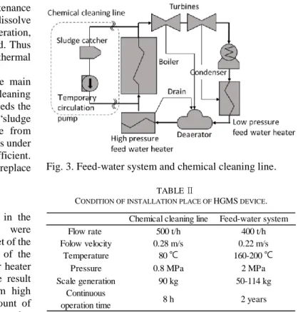
In our previous research, scale concentration in the feed-water and its magnetization generated were investigated [3]. The scale was collected at the outlet of the condenser, the inlet of the deaerator, the outlet of the deaerator, the drain from high pressure feed-water heater and the outlet of boiler as shown in Fig.3. The result indicated that the feed water in the drain from high pressure feed-water heater contains a larger amount of scale than any other place, and its magnetization was also high. Therefore, we decided to install the HGMS system at the drain of high pressure feed-water heater.
HGMS device has more advantages than existing devices in on-line system. If pressure loss of scale removal device is large, the load for feed pump will increase to keep flow rate.
In the HGMS, scale particles are captured by magnetic force, which enables magnetic filter to capture the smaller sized particles than the mesh opening. It enables to remove the scale keeping the pressure loss low. Furthermore, conventional hollow fiber filter and the electromagnetic filter cannot be introduced in high temperature areas, but HGMS device can be introduced by installation of cooling mechanism inside a magnet bore.
2.1.3. Comparison of installation place between off-line and on-line
Table Ⅱ shows two examples of HGMS conditions in off-line and on-line system. Flow velocity is calculated on the assumption that φ800 mm filters are located in a flow
Fig. 2. Whole appearance of chemical cleaning line.
Fig. 3. Feed-water system and chemical cleaning line.
TABLEⅡ
CONDITION OF INSTALLATION PLACE OF HGMS DEVICE.
path. It is reasonable to introduce the HGMS system to both systems because our previous experiments showed that more than 90 % of magnetite can be captured under 0.6 m/s [2]. Comparing on-line conditions with off-line ones, pressure and temperature of off-line are lower than on-line ones, although the scale amount is approximately equal. This means that the possibility of introduction to off-line system will also ensure the removal capacity of the HGMS device for on-line system. Although continuous operating time of the HGMS is different, it will not affect the separation capacity.
2.2. Design of HGMS system
Generally, the magnetic filters have to be washed periodically in HGMS because they are saturated in capture amount and their separation efficiency decrease with accumulation of particles. However, the filters are confined at a closed high pressure and temperature area in this system, so it is not easy to take out the filters from the flow channel and wash. Due to this limitation, we propose a HGMS system that can keep removing without washing until the total amount of scale. In other words, we develop a system which can keep removing the scale during 8 hours in off-line system which is an optimal operational time of chemical cleaning, and 2 years in on-line system that is an interval for maintenance of thermal power plant. This enables to remove the scale continuously without filter washing and also to reduce the risk of device failure compared with the automatic filter washing system.
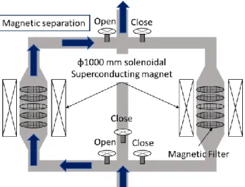
We aim to develop HGMS system that can remove 120 kg scale in order to introduce both off-line and on-line system. In order to achieve the objective throughput, we suggest a parallel HGMS system which consists of two φ1000 mm bore superconductive magnets shown in Fig. 4.
Chemical cleaning line Feed-water system
Flow rate 500 t/h 400 t/h
Folow velocity 0.28 m/s 0.22 m/s
Temperature 80 ℃ 160-200 ℃
Pressure 0.8 MPa 2 MPa
Scale generation 90 kg 50-114 kg
Continuous
operation time 8 h 2 years
In this system, firstly one HGMS device conducts magnetic separation, and then another HGMS device will start separating by switching a flow path when the separation ratio of captured particle decreases. Filter washing is conducted after a chemical cleaning process in off-line system or the maintenance of thermal power plant every two years. In this system, the filter capacity required for one HGMS device is 60 kg.
3. MOCK-UP EXPERIMENT
3.1. Experimental method
In the mock-up experiment, we aimed to demonstrate the practical use of this system and find out possible issues associated with scale-up of the device. This experiment corresponds to one-seventh by comparing a cross-section of magnetic filter to actual equipment. Therefore, we decided the target value of the capture amount as 8.6 kg keeping capture ratio of 90%.
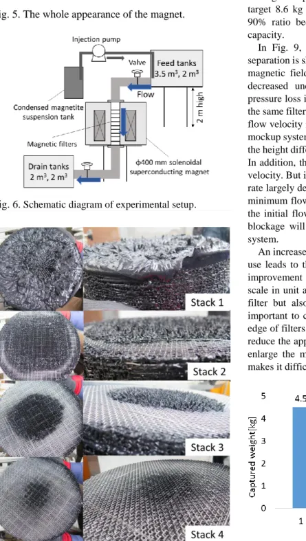
Table II and Fig.5 show the specification and appearance of superconducting magnet, respectively. This magnet is split-paired magnet cooled with two GM refrigerators with φ400 mm room temperature bore and height of 1155 mm [4]. Using this magnet, we arranged the setup shown in Fig. 6. In this setup, magnetite suspension flows by the height difference between feed tanks and collection tanks. 2 m
3and 3.2 m
3feed tanks were located at 2 m high from the ground, and two 2 m
3drain tanks were installed on the ground. Flow velocity was adjusted to around 0.3 m/s, which corresponds to the average flow velocity in the off-line system. Flow volume was about 1.3 m
3/min, which was about 18 times larger than that of previous research [2].
Since the main component of actual scale is magnetite in the thermal power plant adopting AVT targeted in this study, 10 kg commercially available magnetite particles (Sample 1, Mitsui Mining & Smelting Co., Ltd., primary particle diameter 2 μm, average particle diameter 6.8 μm,
saturated magnetization 0.58 T) as the simulated scale was used. The magnetite particles were dispersed in the water at the condensed magnetite suspension tank, and then injected from the outlet of 3.5 m
3tank using an injection pump (PSPZ-4021A, Sanso Electric Co., Ltd., 150L/min at maximum).
As Table Ⅳ shows, we used 150 sheets of φ300 mm filters. To keep the intervals between filter sheets and support its own weight, the nonmagnetic mesh spacer was located between each filter sheet. We stacked 15 filter sheets and 15 spacers alternately for one unit and 10 units were installed into the magnet bore. From the input side, they are named as stack 1-10. The height of the whole filter structure was 604 mm and its weight was about 40 kg.
During magnetic separation, 2 T of maximum magnetic flux density was applied to the filters in order that all filters achieve saturated magnetization. Magnetic separation was continued for 150 seconds and flow rate was measured at the same time to determine whether the pressure loss was increased or not.
After magnetic separation, installed filters was pulled out from the separation space, and magnetite particles attached to the filters were removed by high-pressure water sprayer. Collected slurry was decanted and dried at 60℃
for 72 hours. After that, dry weight of the sample was measured and capture ratio was calculated by eq. 1. Here, 𝑊
𝑖𝑛and 𝑊
𝑜𝑢𝑡respectively represent the weight of input and output of magnetite particle.
𝐶𝑎𝑝𝑡𝑢𝑟𝑒𝑑 𝑟𝑎𝑡𝑖𝑜[%] =𝑊𝑖𝑛[𝑘𝑔] − 𝑊𝑜𝑢𝑡[𝑘𝑔]
𝑊𝑖𝑛[𝑘𝑔] × 100
(1)
TABLEⅢ
SPECIFICATIONOFTHESUPERCONDUCTINGMAGNET.
TABLEⅣ
FILTERCONDITIONSOFMOCK-UPSYSTEM.
3.2. Experimental result
The appearances of each filter stack after the experiment are shown in Fig.7. Magnetite particles are intensively captured around the outer edge on the inflow side of filter stack1, and then gradually decreased as the downstream.
The captured area of magnetite particle changed from the Filter material Magnestain
®Filter wire diameter 1 mm
Filter diameter 300 mm
Mesh opening 3.2 mm
Number of filter 150
(15 filters × 10 stacks)
Bore diameter 400 mm
Height 1150 mm
Maximum magnetic
flux density 3 T
Fig. 4. Schematic diagram of parallel HGMS system.
Fig. 5. The whole appearance of the magnet.
Fig. 7. Pictures the stacks after experiment.
peripheral to the center area of the filter in the latter filter stack. Next, the captured amount of each stack is shown in Fig.8 and the change in flow velocity during the experiment is shown in Fig.9. Fig.8 shows that totally 6.7 kg of magnetite particle was captured, but they are intensively trapped by the 1st stack on the inflow side and are not trapped after 5th stack. Considering that 2.3 kg magnetite out of 10 kg used in the experiment remained in the suspension tank, the total weight passed to HGMS system was 7.7 kg. Consequently, the captured amount 6.7 kg corresponds to the recovery ratio of 87 %, and we achieved a value close to the target value of 90%. If 10 kg of magnetite particle was drained, it is considered that the target 8.6 kg of magnetite particle could be captured at 90% ratio because the outflow filter still had removal capacity.
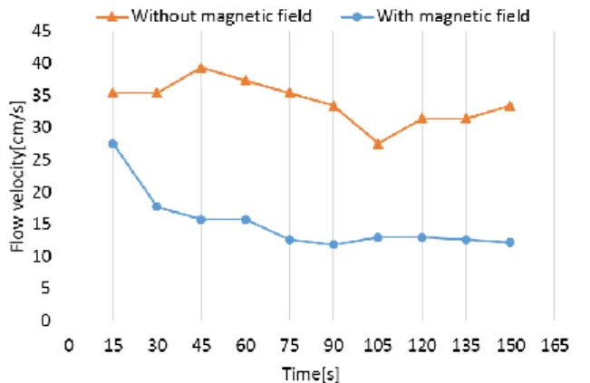
In Fig. 9, change in flow velocity during magnetic separation is shown compared with that without applying a magnetic field. Fig. 9 indicates flow velocity gradually decreased under a magnetic field, which means that pressure loss increased. Our previous lab-scale study with the same filter specification neither showed decrease in the flow velocity nor increase in the pressure loss. But in this mockup system, the suspension of magnetite was flown by the height difference, so the flow rate cannot be controlled.
In addition, the blockage of the filters decreases the flow velocity. But in the actual chemical cleaning line, the flow rate largely depends on the conditions of the plant and the minimum flow rate is as low as about 0.1 m/s. Therefore, the initial flow rate is appropriate and the dissolution of blockage will be the most important issue in the actual system.
An increase in pressure loss by the blockage in practical use leads to the increase in the load of a feed pump, so improvement should be required. The amount of captured scale in unit area thought to be equalized not only in the filter but also between the filters. In both cases, it is important to capture particles without blocking the outer edge of filters. In order to achieve this, it is appropriate to reduce the applied magnetic field at the inflow side, or to enlarge the mesh size of filters on the inflow side that makes it difficult to trap the particles.
Fig. 8. Captured weight of magnetite on each stack.
Fig. 6. Schematic diagram of experimental setup.
Fig. 9. Change in flow velocity with and without magnetic field.
5. SUMMARY
We designed a parallel HGMS system and conducted one-seventh scaled experiment in order to study the possibility introducing the system into feed-water line and chemical cleaning line of thermal power plant. In the experiment, 150 sheets of φ300 mm filters were arranged in φ400 mm superconducting magnet, and succeeded to capture 6.7 kg magnetite by the filters although blockage was partly confirmed on the inflow filter. Average captured ratio was 87%, which is very close to the target, so we could demonstrate the practical utility of the system.
In our future work, we are going to resolve blockages by optimizing applied magnetic field or enlarging the mesh size of the filter.
ACKNOWLEDGMENT
This research was partly supported by “Advanced Low Carbon Technology Research and Development Program (ALCA)” of Japan Science and Technology Agency (JST).
REFERENCES
[1] M. Siddhartha Batt, “Effect of water side deposits on the energy performance of coal fired thermal power plants,” Energy Conversion and Management, vol. 47, pp. 1247-1263, 2006.
[2] S. Shibatani, M. Nakanishi, N. Mizuno, F. Mishima, Y. Akiyama, H. Okada, N. Hirota, H. Matsuura, T. Maeda, N. Shigemoto, and S.
Nishijima, “Study on magnetic separation device for scale removal from feed-water in thermal power plant,” IEEE transaction on applied superconductivity, vol. 26, no. 4, 2016.
[3] H. Okada, K. Imamura, N. Hirota, T. Ando, S. Shibatani, M.
Nakanishi, N. Mizuno, F. Mishima, Y. Akiyama, S. Nishijima, H.
Matsuura, T. Maeda, and N. Shigemoto, “Development of a magnetic separation system of boiler feedwater scale in thermal power plants,” IEEE transaction on applied superconductivity, vol.
26, no. 3, 2016.
[4] T. Kiyoshi, S. Matsumoto, M. Yoshikawa, H. Konno, N.
Shimoyama, and M. Tobita, “Cryocooler-cooled split-paired magnet for anisotropic conductive sheet production,” IEEE transaction on applied superconductivity, vol. 16, no. 2, 2016.