Vol. 13, No. 5 pp. 2325-2331, 2012
Planar Square-spiral Antenna using a strip conductor
Doo-Yeong Yang
and Min-Soo Lee
1Dept. of Telecommunication Engineering, Jeju National University
2Dept. of Telecommunication Engineering, Daejin University
도체스트립을 이용한 평판사각 스파이럴 안테나
양두영
, 이민수
제주대학교 통신공학과, 대진대학교 통신공학과
Abstract Planar square-spiral antenna using a strip conductor is proposed and analyzed for RFID system in UHF band operating from 860MHz to 960MHz. By varying the length of common line, detached distance, strip line-space, strip line-width and the number of spiral turn, the optimized antenna are designed and fabricated in compact size without a matching-stub between the input port of the proposed antenna and RFID tag chip. From the optimized results, the frequency bandwidth in VSWR<2 has covered 100MHz in the RFID UHF band. The antenna gain has obtained 3.5dBi at the center frequency of 910MHz and the desired beam pattern has shown directional pattern on elevation and azimuth angle. Therefore, the proposed antenna is suitable for practical RFID applications requiring various tag chips with the specific input impedance.
요 약 UHF 대역인 860MHz~960MHz에서 동작하는 RFID 시스템용으로 도체스트립을 이용한 평판사각 스파이얼
안테나를 제안하고 분석하였다. 도체스트립의 공통선 길이, 분리간격, 선폭, 선간격, 스파이럴 회전수를 변화시켜서 안 테나 입력임피던스와 RFID 테그칩 간을 정합스터브 없이 소형으로 설계하고, 최적화된 안테나를 제작하였다. 최적화 된 결과로부터, VSWR<2인 범위의 주파수대역은 RFID 초고주파 대역인 100MHz를 포함한다. 안테나 이득은 910MHz 중심주파수에서 3.5DBi이고, 빔패턴은 수직과 수평방향으로 지향성 패턴을 갖는다. 따라서 제안된 안테나는 규정된 입력임피던스를 갖는 다양한 형태의 테그칩을 요구하는 실질적인 RFID 응용에 적합하다.
Key Words : Planar square-spiral antenna, strip conductor, RFID tag, UHF band
“This work was supported by the Daejin University Research Grants in 2012"
*Corresponding Author : Min-Soo Lee
Tel: +82-10-5232-9795 email: [email protected]
Received March 9, 2012 Revised (1st March 30, 2012, 2nd April 5, 2012) Accepted May 10, 2012
1. Introduction
In recent years, the industrial growth of radio frequency identification (RFID) system comes to largely change economical activities, market frameworks and educational environments since it can be applied various applications. Also, RFID technology is going to substitute the bar-code system being used now and to be basis on ubiquitous computing environments such as ubiquitous sensor network (USN) [1]. In 2004, International
organization for standardization (ISO) and EPC-global announced their specifications for RFID Air-interface which is UHF RFID protocol for communications at 860~960MHz (ISO 18000-6, EPC Class-1 Generation-2) [2].
RFID System is composed of interrogator and tag.
RFID tag is designed to be fabricated with various structures - shape, size, characteristics - according to frequency band and application object. And its volume mainly depends on antenna radiation pattern, the input
impedance and property of tag chip. The size of RFID tag relies on the antenna dimension connected with tag chip.
Antenna for RFID tag with very small size has many applications, but it can not affirm reliability for its property because of fringing effect caused by the strip-conductors. Therefore, in miniaturization of antenna dimension, it is important to design the antenna to be satisfied the desired characteristics with reliable performance [3][4]. In the scope of reliable performance, various antennas using a micro-strip patch, half-wavelength dipole and dielectric rod were presented in an ultrahigh frequency (UHF) band [5-7]. However, achieving effectively minimization of antenna dimension is limited in practical applications. Since antenna dimension is proportional to wavelength of operating frequency. In frequency range of UHF RFID allocated at the 900MHz band, antenna size has generally 15cm. This is inadequate size for application of the RFID tag. Also, the presented antennas earlier are difficult to minimize antenna dimension and freely change antenna impedance [8][9].
Therefore, matching circuit for matching condition between antenna input impedance and input impedance of RFID tag chip is generally required and complicated in processing.
In this paper, the antenna matched by input impedance of RFID tag chip without the matching stub as modifying design parameters of the antenna is proposed with compact size. Also, the desired beam pattern, broad frequency bandwidth and low voltage standing wave ratio (VSWR) are obtained in the frequency range of UHF RFID band operating at 860~ 960MHz.
2. Analysis and configuration of planar square-spiral antennan
2.1 Configuration of the proposed antenna Spiral antennas are classified into various types;
archimedean spiral [10-11], square spiral [12-14] and conical spiral [15] etc. Most of conventional spiral antennas can achieve desirable gain, directional beam and broaden impedance characteristic, as long as the length and parameters of the antenna are properly chosen, but not a ideal frequency independent antenna. However, such antennas are inherently circularly polarized with low gain
and have a complicated structure to implementation and construction. In order to resolve the weakness, two pairs of twin planar square-spiral antenna proposed in this paper can be used to increase the directive gain, and to get a compact size and broadband-limited characteristics in UHF RFID frequency band.
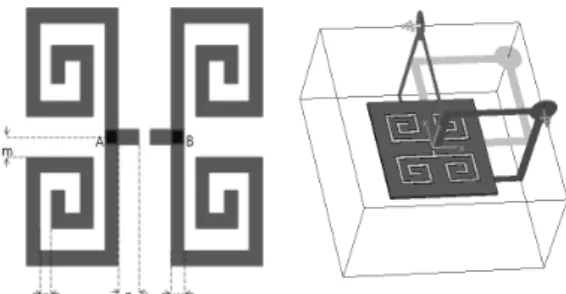
Fig. 1 shows the antenna geometry of a planar square-spiral antenna using a strip conductor for RFID tag. The proposed antenna is composed of two pairs of twin planar square-spirals. Two pairs of twin planar square-spirals are branched from common line which is connected with input terminals of RFID tag chip. The two pairs of twin planar square-spirals are placed symmetrically on the x-axis. And, each pair of twins is located symmetrically on the y-axis. The twins on the up-side and the twins on the down-side are connected by the positive port and the negative port of RFID tag chip, respectively. The current distributions between vertical lines of the twins are the same direction and the current distributions between horizontal lines of the twins are the opposite direction. Since the currents are fed with the equi-phase distribution on the up-side and contra-phase on the down-side. That is why total length of strip conductor of the antenna is optimized within half-wavelength.
In Fig. 1, the twin square-spirals are located at the position apart the length of common line n along to y-axis line from RFID tag chip and the detached distance m along to x-axis line from a common node A and B, and those are coiled by the square-spiral shapes with strip line-width w and strip line-space p. Based on the antenna structure described earlier, antenna radiation pattern, input impedance, gain and frequency bandwidth are controlled by the length of common line n, the detached distance m, strip line-width w, strip line-space p and the number of square-spiral turn N.
[Fig. 1] Configuration for proposed antenna
2.1.1 Influence of the strip line-space p Fig. 2 shows impedance variations of the antenna simulated on increasing of strip line-space p, in this case, the other parameters are fixed as follows: length of common line n=8mm, detached distance m=10mm, strip line-width w=0.75mm, number of turn N=3.5. Fig. 2(a) and Fig. 2(b) are real part and imaginary part of the antenna input impedance. By increasing the strip line-space from 2mm to 10mm in 2mm step, the resonance point of antenna impedance is shifted into lower frequency band. Because it is due to decrease of reactance component caused by diminishment of coupling effect between strip lines.
(a) Real part of input impedance
(b) Imaginary part of input impedance
[Fig. 2] Impedance variations of antenna simulated on increasing of strip line-space p
2.1.2 Influence of the length of common line n Fig. 3 shows impedance variations of the antenna simulated on increasing of common line lengths n between two twin square-spirals, in this case, the other parameters are p=6mm, m=10mm, w=0.75mm and N=3.5.
By increasing the length of common line from 0mm to 20mm in 4mm step, the resonance point of antenna impedance is shifted into lower frequency band. Because
it is due to reduction of reactance component caused by weakness of coupling effect between two twin square-spirals on the y-axis. It is shown that the separated distance between two twin square-spirals is longer.
(a) Real part of input impedance
(b) Imaginary part of input impedance
[Fig. 3] Impedance variations of antenna simulated on increasing of common line length n
2.1.3 Influence of the detached distance m Fig. 4 shows impedance variations of the antenna simulated on increasing the detached distance m from common node A and B, in this case, the other parameters are n=8mm, p=6mm, w=0.75mm and N=3.5. According to increasing the detached distance from 5mm to 25mm in 5mm step, the resonance point of antenna impedance is shifted into lower frequency band. Because it is due to reduction of reactance component caused by weakness of coupling effect between twin square-spirals on the x-axis.
It is shown that the detached distance between twin square-spirals is receded in a distance.
(a) Real part of input impedance
(b) Imaginary part of input impedance
[Fig. 4] Impedance variations of the antenna simulated on increasing of the detached distance m
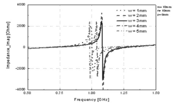
2.1.4 Influence of the length of line-width w Fig. 5 shows antenna simulated on increasing strip line-width w, in this case, the other parameters are m=10mm, n=10mm, p=6mm and N=3.5. According to increasing the strip line-width w=1~5mm, the resonance point of antenna impedance is abnormally changed.
According to widening of strip line-width, the ratio of strip line-width to strip line-space is increased. It is due to increase of capacitive reactance component and decrease of inductive reactance component caused by strength of coupling effect among strip lines with in each square-spiral.
(a) Real part of input impedance
(b) Imaginary part of input impedance
[Fig. 5] Impedance variations of the antenna simulated on increasing of the strip line-width w
2.1.5 Influence of the number of square-spiral turn N
Fig. 6 shows impedance variations of the antenna simulated on increasing the number of square-spiral turn N, in this case, the other parameters are m=10mm, n=10mm, p=6mm and w=0.75mm. According to increasing the number of square-spiral turn from 2mm to 4mm, the resonance point of antenna impedance is repeatedly occurred with the specific period. It is due to increase of inductive reactance component caused by increasing the number of square-spiral turn.
(a) Real part of input impedance
(b) Imaginary part of input impedance
[Fig. 6] Impedance variations of the antenna simulated on increasing of the number of turn N
(a) matrics
(b) proposed antenna
[Fig. 7] Comparison of signal voltage between matrics and proposed RFID antenna
Fig. 7 shows comparison of the signal voltage measured by oscilloscope between matrics and proposed RFID tag. The voltage signal strength transmitted from the proposed RFID antenna is larger ten times than that of matrics antenna. Because, the proposed antenna has good performance of antenna gain.
3. Results of the proposed antenna
From the results in Fig. 2 through Fig. 7, the antenna impedance as modifying the design parameters of m, n, p, w, N is adequately matched by input impedance of RFID tag chip without matching stub. After a thorough parametric study of a planar square-spiral antenna, the desired beam pattern, broad frequency bandwidth and low VSWR are obtained in operating frequency range of RFID system.
Fig. 8 shows the fabricated antenna. This antenna does not need the matching-stubs in matching the impedance between input terminal (132-j553Ω) of RFID chip and
input port of tag antenna. The optimum design parameters are set as follows: m=11.1mm, n=8.8mm, p=1.1mm, w=0.4mm and N=3.5.
Based on the proposed antenna design parameters described earlier, the antenna is fabricated on Teflon substrate with permittivity of єr=3.2 and thickness of 0.78mm. The fabricated antenna has compact size as dimension of 4.15×4.5 cm2.
[Fig. 8] photograph of fabricated antenna
Fig. 9 shows the analyzed return loss of fabricated antenna. The return loss of the antenna is testified by vector network analyzer and obtained below -10dB in VSWR<2 at 860~960MHz. The frequency bandwidth includes the frequency ranges of UHF RFID system operating at 900MHz band.
[Fig. 9] Return loss of proposed antenna
Fig. 10 shows the simulated radiation patterns of the proposed antenna at 910MHz. The pattern Eθ on elevation angle and the pattern Eφ on azimuth angle are shown on phi angle of gray circular line and theta angle of black circular line, respectively. Also, the total radiation pattern is shown on three dimensional graphics. The directivity of proposed antenna with maximum directional gain is 3.5dBi at z-axis. Extending of the common line length n
between two twin square-spirals improves the directivity of the beam pattern. Therefore, we can design an antenna with directive gain as varying the common line length n between twin square-spirals and appropriately control the radiation pattern according to application objects.
[Fig. 10] Radiation pattern of proposed antenna
4. Conclusion
A planar square-spiral antenna is proposed and testified for the UHF RFID system operating at 860MHz to 960MHz. By varying the length of common line, detached distance, strip line-space, strip line-width and the number of turn, the optimized antenna are designed and fabricated by compact size without a matching-stub between the input impedance of the proposed antenna and RFID chip.
The obtained frequency bandwidth in VSWR<2 has covered 100MHz in the UHF RFID band. The antenna gain has obtained 3.5dBi at the center frequency of 910MHz and the desired beam pattern has shown omni-directional pattern on elevation and azimuth angle.
Therefore, this antenna fabricated without matching-stub is suitable for practical RFID applications requiring various tag chips with the specific input impedance. As a result, it is very meaningful to devise a compact antenna with simple structure and low cost. Two pairs of twin planar square-spiral arms at the antenna terminal is one of the effective topology of miniature antenna.
References
[1] K. Frinkeneller, “RFID Handbook”, John Wiley & Sons, 2001.
[2] T. Flor, W. Niess and G. Vogler, “RFID: The integration of contactless identification technology and mobile computing”, 7th International conference on Telecommunications, ConTEL 2003, June 2003.
[3] G. Marrocco, A. Fonte, F. Bardati, “Evolutionary design of miniaturized meander-line antennas for RFID applications”, Antenna and Propagation Society International Symposium, IEEE, vol. 2. June 2002.
[4] R. Bridgelall, “Enable mobile commerce through pervasive communications with ubiquitous RF tags”, Wireless Communications and Networking, IEEE, vol.3, Mar. 2003.
[5] C. A. Balanis, “Antenna Theory, 2nd Ed”, John Wiley&Sons, 2001.
[6] R. F. Harrington,“Time Harmonic electromagnetic field”, John Wiley & Sons Inc., 1961.
[7] W. L. Stutzman and G. A. Thiele, “Antenna Theory and Design”, John Wiley & Sons Inc., 1981.
[8] T. E. Morgan, “Spiral antenna for ESM”, IEEE Proc.
Part H, vol. 132, no. 4, pp. 245-251, July 1985.
[9] C. Su, Y. Liu, W. Chen, Y. Cheng, and K. Wong,
“Broadband circularly polarized printed spiral strip antenna for 5-GHz WLAN operation”, Microwave and Optical Technology Letters, vol. 41, no.3, 2004.
[10] H. Nakano, R. Satake, and J. Yamauchi, “ Extremely Low-Profile, Single-Arm, Wideband Spiral Antenna Radiating a Circularly Polized Wave”, IEEE Transactions on Antennas and Propagation, Vol. 58, No. 5, pp.
1151~1520, May 2010.
[11] T. Chen and G. H. Huff, “Stripline-Fed Archimedian Sprial Antenna”, IEEE Transactions on Antennas and Propagation Letters, Vol. 10, pp. 346~349, May 2011.
[12] H. Nakano, M. Ikeda, K. Hitosugi, and J. Yamauchi,
“A Spiral Antenna Sandwiched by Dielectric Layer”, IEEE Transactions on Antennas and Propagation, Vol.
52, No. 6, pp. 1417~1423, June 2004.
[13] B. Kang, K. Hong, I. Koh, D. Yang, W. Song, S.
Kim, C. Kim, and K. Lee, “Sprial Antenna using Conductor strips for an RFID Tag”, Patent No.
10-0648084, Nov. 2006.
[14] H. Nakano, J. Miyake, M. Oyama, and J. Yamauchi,
“Metameterial Spiral Antenna”, IEEE Transactions on Antennas and Propagation Letters, Vol. 10, pp.
1555~1558, 2011.
[15] H. Youn, N. Celik, M. Iskander, J. Baker, and J.
Graham, Seibert Murphy, “Miniaturized conical spiral antenna with tapered resistive roading and corrugated arms”, IEEE International Symposium on Antennas and Propagation (APSURSI), pp. 1185 - 1188, July 2011.
Doo-Yeong Yang
[Regular member]• Feb. 1984 : Cheju Nat'l Univ., Dept. of Telecomm. Eng., BS
• Feb. 1989 : Hanyang Univ., Dept. of Electronic and Telecomm.
Eng., MS
• Feb. 1992 : Hanyang Univ., Dept. of Electronic and Telecomm.
Eng., PhD
• Jan. 2001 ~ July. 2002 : Utah State Univ., Dept. of Electrical and Computer Eng., Int'l Research Prof.
• Mar. 1992 ~ current : Jeju Nat'l Univ., Dept. of Telecomm., Professor
<Research Interests>
RF devices, microwave circuits, wireless and satellite communication systems.
Min-Soo Lee
[Regular member]• Feb. 1984 : Hanyang Univ., Dept. of Electronic and Telecomm.
Eng., BS
• Feb. 1987 : Hanyang Univ., Dept. of Electronic and Telecomm.
Eng., MS
• Feb. 1994 : Hanyang Univ., Dept. of Electronic and Telecomm.
Eng., PhD
• Mar. 1995 ~ current : Daejin Univ., Dept. of Telecomm., Professor
<Research Interests>
RF devices, microwave circuits, RFID