• 검색 결과가 없습니다.

Evaluation of The Moment Resistance Joint Strength of Larch Glulam Using Glass Fiber Reinforced Wood Plate

N/A
N/A
Protected

Academic year: 2021

Share "Evaluation of The Moment Resistance Joint Strength of Larch Glulam Using Glass Fiber Reinforced Wood Plate"

Copied!
8
0
0

로드 중.... (전체 텍스트 보기)

전체 글

(1)

Evaluation of The Moment Resistance Joint Strength of Larch Glulam Using Glass Fiber Reinforced Wood Plate 1

Yo-Jin Song

2

⋅Hong-Ju Jung

2

⋅Hyun-Ho Park

2

⋅Hak-young Lee

2

⋅Soon-Il Hong

2,†

ABSTRACT

As a way of developing wooden joint development, a glass fiber reinforced wood plate was manufactured to replace a steel plate. Also, the fracture toughness was evaluated. Through application to a cantilever-type specimen made of a column and a beam, the moment resistance performance was evaluated.

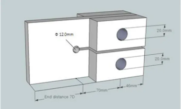
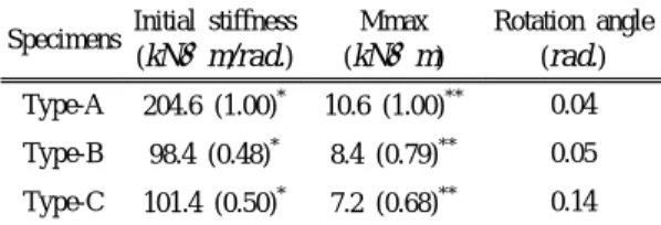
For the fracture toughness specimen of the wood plate, 12 types were manufactured by varying the combination of a main member (veneer and plywood) and reinforcement (glass fiber sheet and glass fiber cloth). The results of the fracture toughness test indicated that the 5% yield load of the specimen using plywood was 18% higher than that of the specimen using veneer, and that the specimen reinforced by inserting glass fiber sheets between testing materials (Type-3-PS) had the highest average 5% yield load 4841 N. Thus, a moment resistance strength test was performed by applying Type-3-PS to a column-beam joint. The results of the test indicated that compared to the specimen using a steel plate and a drift pin (Type-A), the maximum moment ratio of the specimen using a glass fiber reinforced wood plate (Type-3-PS) and a drift pin (Type-B) was 0.79; and that a rupture occurred in the wood plate due to high stiffness of the drift pin. The maximum moment ratio of the specimen using a glass fiber reinforced wood plate (Type-3-PS) and a glass fiber reinforced wooden laminated pin (Type-C) was 0.67, which showed low performance.

However, unlike Type-A, a ductile fracture occurred on Type-C, and the load gradually decreased even after the max- imum moment.

Keywords : glass fiber reinforced wood plate, fracture toughness, moment resistance performance, glulam

1

Date Received May 9, 2014, Date Accepted June 14, 2014

2

Department of Forest Biomaterials Engineering, College of Forest and Environmental Sciences, Kangwon National University, Chuncheon 200-701, Korea

Corresponding author : Soon-Il Hong (e-mail: [email protected])

1. INTRODUCTION

The strength performance of a wooden structure depends largely on the strength performance of joints as well as the strength of the members. In most jointing methods other than mortise and tenon, which is a traditional jointing method, a metal jointing ma-

terial is inserted by making slits between members,

and they are combined using a drift pin or a bolt

from the side. This jointing method has a high level

of reliability due to the high stiffness of the metal

jointing material. However, in most cases, brittle

fracture, where a fracture occurs in a moment after

the maximum strength of a structure, occurs due to

(2)

the relatively low stiffness of the wood. Also, in case of fire, the deformation that starts from a metal jointing material being exposed to the exterior due to high temperature could degrade the stability of the entire structure; and in case of exposure to the open air, the corrosion of a metal jointing material could spread to the wood and could also induce an aes- thetic mismatch.

To resolve these problems, Uchisako and Tokuda, 2009 replaced the steel plate of a steel plate in- sertion-type dowel joint with a GFRP plate, and per- formed a tensile-type shear strength test of the joint.

The results indicated that the ductility of the joint with the GFRP plate insertion was satisfactory, and the yield load (90%) was close to that of the steel plate insertion. Also, as part of wooden joint devel- opment, we previously performed a tensile-type shear strength test of a glulam joint using a GFRP-re- inforced wood pin and a wood plate; the results in- dicated that the performance was 12% higher than that of the specimen using a metal jointing material, and that the toughness was good after the maximum load (Song et al. 2014). These results suggest that for jointing between wood, a wooden jointing material could be used to replace metal jointing material, and that high performance could be obtained if wood with the same stiffness as that of the main member is used.

On the other hand, for the design of a wooden structure, the bearing strength of a wooden material is an important factor. However, the reinforcement used in a reinforced wooden material does not have a large effect on bearing strength, and thus the re- inforcing effect cannot be examined. Therefore, frac- ture toughness, which is a measure of the resistance of a material to fracture, would be an important fac- tor for the application of a glass fiber reinforced wooden jointing material. In previous studies on fracture toughness, the relation between the width/

thickness of a wood plate and fracture toughness has

been investigated, and the fracture toughness test of GFRP indicated that glass fiber is a material with high resistance to splitting (Garg, 1986; Leonard et al. 2009). Also, among the fracture toughness char- acteristics of GFRP reinforced larch laminated wood, Kim, observed an increase in the strength and an in- crease in the toughness (Kim, 2012).

Therefore, in this study, glass fiber reinforced wood plates were manufactured by varying the form, insertion position, and combination form of re- inforcement, and the fracture toughness performance was examined. Also, the moment resistance specimen of a column-beam joint using a glass fiber reinforced wood plate was manufactured, and the joint strength was compared with that of a joint using the existing metal jointing material.

2. MATERIALS and METHODS 2.1. Testing Materials

As the testing materials used for the manufacture of glass fiber reinforced wood plates, Radiata pine (Pinus radiata D. Don) veneer with a thickness of 2.7 mm and lauan (Pentacme contorta (Vidal.) Merr.

and Rolfe) plywood with a thickness of 2.7 mm, which are currently available on the market, were used. For the reinforcement, glass fiber cloth with a thickness of 0.5 mm, where glass fiber bundles had been woven in a plain weave. Also, a glass fiber sheet with a thickness of 1.3 mm, where glass fiber had been molded using an epoxy resin, were used.

2.2. Manufacture of The Fracture Toughness Specimen of a Glass Fiber Reinforced Wood Plate

For the manufacturing of fracture toughness speci-

mens, two types of materials (veneer and plywood)

(3)

Fig. 1. GFRP reinforced wood plates in accordance with combination of the main member and the reinforcement.

Type Main member Reinforcement Sample label

Type-1 Veneer

Not using Type-1-V

Plywood Type-1-P

Type-2

Veneer

Glass fiber cloth Type-2-VC

Plywood Type-2-PC

Veneer

Glass fiber sheet Type-2-VS

Plywood Type-2-PS

Type-3

Veneer

Glass fiber cloth Type-3-VC

Plywood Type-3-PC

Veneer

Glass fiber sheet Type-3-VS

Plywood Type-3-PS

Type-4 Veneer

Both cloth and sheet Type-4-V

Plywood Type-4-P

Table 1. Summarizes the nomenclature of the fracture toughness specimens depending on the combination of the main member and the reinforcement

were used; and for the reinforcement, two types of materials were used. A total of 12 types were manu- factured through different combinations using four kinds of methods.

Type-1, which is a control specimen, is a speci- men in which the testing materials of each lamina was stacked in five laminae crossed in the direction perpendicular to the fiber. For Type-2, the volume ratio of the reinforcement between the outermost lamina and the inner lamina of the testing materials

was made to be 12% (glass fiber cloth) and 30%

(glass fiber sheets), respectively. For Type-3, the volume ratio of the reinforcement was identical to that of Type-2, but each sheet was inserted between each lamina of the main member. For Type-4, the two kinds of reinforcements were used together, and each glass fiber cloth was inserted between the out- ermost lamina and the inner lamina of the main member while each glass fiber sheet was inserted between the inner lamina and the middle lamina. For the stacking, a resorcinol resin was used between woods and between wood and glass fiber cloth. A polyvinyl acetate resin was also used between wood and a glass fiber sheet (Park et al. 2009). After the application of adhesive, densification of the speci- men was performed by applying a pressure of 1.96 N/mm

2

for 1 hour at 150℃.

The manufactured laminated wood was made to

be a compact tension-type fracture toughness speci-

men suggested by ASTM D5045-99. As shown in

Fig. 2, for the shape of the specimen, a bolt hole

(12 mm) was made on the laminated wood with a

length of 200 mm and a width of 100 mm using an

(4)

Fig. 4. Shape of glass fiber reinforced wood pin.

Fig. 2. Configuration of compact-tension test specimens.

Fig. 3. Setup of fracture test.

end-distance of 7D, and an artificial crack with a width of 4 mm was made on the opposite end-distance.

To apply a tensile load to the specimen, fixing part bolt holes with a diameter of 20 mm were made on both sides of the crack. To prevent fracture at the specimen fixing part during the test, laminae with a thickness of 20 mm and a length of 100 mm were bonded on both sides.

2.3. Fracture Toughness Test of a Glass Fiber Reinforced Wood Plate

The fracture toughness evaluation was performed using a compact-tension test. As shown in Fig. 3, the specimen was installed between the upper load cell and the lower fixing part of a universal testing machine (Instron 4482), where it was fixed using a pin (diameter of 20 mm) so that the specimen could rotate when a tensile load is applied. In this regard, the clearance between the specimen and the side plate of the fixing part was minimized. Furthermore, care was taken not to apply a compressive or tensile load before the test. The load and the crack tip opening displacement (CTOD) were measured using the universal testing machine, and the cross head speed was set to 5 mm/min.

2.4. Manufacture of The Moment Resistance Specimen of a Column-beam Joint Using a Glass Fiber Reinforced Wood Plate

Type-A, which used a steel plate and a drift pin

as the metal connector; Type-B, which used a glass

fiber reinforced wood plate and a drift pin; and

Type-C, which used a glass fiber reinforced wood

plate and a glass fiber reinforced wood pin, were

manufactured. For the column and the beam, a glu-

lam (width of 150 mm and thickness of 170 mm), in

which domestic larch (Larix kaempferi Carr.) lamina

was stacked in six layers, was manufactured and

utilized. As shown in Fig. 4, slits were made in the

manufactured column and beam, and they were com-

bined using each jointing material. The glass fiber

reinforced wood pin was manufactured using the

same method as that used for the reinforced wood

plate. Then, it was made to be a diameter of 20 mm

and a length of 150 mm, as shown in Fig. 4.

(5)

Fig. 5. Specimens of moment resistance performance test.

Fig. 6. Load-CTOD curves of Glass fiber reinforced wood plate made by veneer.

Fig. 7. Load-CTOD curves of Glass fiber reinforced wood plate made by plywood.

2.5. Moment Resistance Strength Test of a Column-beam Joint Using a Glass Fiber Reinforced Wood Plate

The column of the completed specimen was fixed, and a loading rate of 10 mm/min was applied to the beam, which was 300 mm away from the center of the column. To measure the deformation depending on the load, a displacement meter with a capacity of 50 mm was installed as shown in Fig. 5. Furthermore, measurement was made using a data logger (TDS- 303).

3. RESULTS and DISCUSSION

3.1. Fracture Toughness Test of a Glass Fiber Reinforced Wood Plate

The average maximum load of the Type-1-V specimen manufactured using only the veneer was 1324 N. The average 5% yield load of it was 1064 N. As the veneer was cross-stacked, splitting did not occur in the fiber direction, and momentary splitting occurred in the direction perpendicular to the fiber.

Type-2-VC and Type-3-VC, had been reinforced

with the glass fiber cloth. The average maximum

loads of them were 3526 N and 3365 N, re-

spectively, They were 2.6 times and 2.5 times higher

(6)

Specimens Ave. P max ( N ) Ave. P

Q

( N ) Ratio

*

Type-1 V 1324 1064 1.00

P 1993 1898 1.78

Type-2

VC 3526 3362 3.15

PC 3773 3452 3.24

VS 3445 3090 2.85

PS 4373 4046 3.80

Type-3

VC 3365 3086 2.90

PC 3696 3470 3.26

VS 3832 3545 3.33

PS 5242 4866 4.56

Type-4 V 4693 4149 3.89

P 4741 4097 3.85

Ratio

*

: Ratio of the average yield load relative to Type-1-V

Table 2. Results of fracture toughness test

than that of the Type-1-V specimen. For the two specimens, splitting occurred in the direction perpen- dicular to the fiber; and a ductile fracture was ob- served as shown in the load-CTOD curves in Fig. 6 because the glass fiber cloth suppressed splitting.

The average maximum loads of Type-2-VS and Type-3-VS, which had been reinforced with the glass fiber sheet, were 3445 N and 3832 N, respectively;

and the average 5% yield loads were 3086 N and 3545 N, respectively. For the specimen reinforced with the glass fiber sheet, the stiffness was higher than that of the specimen reinforced with the glass fiber cloth, but splits occurred to the fiber direction.

It is thought because fiber orientation of glass fiber sheet was same as longitudinal direction of wood plate. The average maximum load of Type-4-V, which used the two reinforcements together, was 4693 N, which was 3.5 times higher than that of the Type-1-V specimen; and the average 5% yield load was 3.9 times higher. The glass fiber sheet that had reinforced the inner layer increased the stiffness of the wood plate, and the glass fiber cloth of the outer layer suppressed the splitting occurring in the fiber

direction.

The average maximum load of the Type-1-P specimen manufactured using only the plywood was 1993 N, and it was 1.5 times higher than that of the Type-1-V specimen manufactured using only the veneer. The average maximum loads of Type-2-PC and Type-3-PC, which had been reinforced with the glass fiber cloth, were 3773 N and 3696 N. They were 1.9 times and 2.2 times higher than that of the Type-1-P specimen, while the average 5% yield loads were 1.8 times and 2.1 times higher, respectively.

Type-2-PS and Type-3-PS had been reinforced with the glass fiber sheet. The average maximum loads of them were 4373 N and 5242 N, respectively.

Notably, it is thought that for Type-3-PS, high per- formance could be obtained because unlike the ve- neer, the plywood suppressed the splitting occurring in the fiber direction although the glass fiber sheet was used. The average maximum load of Type-4-P was 4741 N. The fracture shape showed a similar trend to that of Type-4-V, but the bonding layer of the plywood was ruptured. Because the bonding strength of the interior of the plywood was lower than the bonding strength between the reinforcement and the plywood.

3.2. Results of The Moment Resistance Strength Test

The maximum moment of Type-A, which used a

steel plate and a drift pin was 10.6 kN⋅m and the

deformation angle was 0.04 rad. The initial stiffness

was the highest (204.6 kN⋅m/rad.) but a large rup-

ture occurred at the end-distance of the column and

the beam. This fracture shape is typical for a frac-

ture of a wooden structure joint using a metal joint-

ing material. It could be because the stiffness of a

metal jointing material is much higher than that of

wood. For Type-B, a wood plate that had been made

(7)

Specimens Initial stiffness ( kNm/rad. )

Mmax ( kNm )

Rotation angle ( rad. ) Type-A 204.6 (1.00)

*

10.6 (1.00)

**

0.04 Type-B 98.4 (0.48)

*

8.4 (0.79)

**

0.05 Type-C 101.4 (0.50)

*

7.2 (0.68)

**

0.14 Ratio

*

: Ratio of the initial stiffness relative to Type-A Ratio

**

: Ratio of the maximum moment relative to Type-A

Table 3. Properties of moment resistance test

Fig. 8. Moment-rotation angle curves of moment re- sistance tests.

using the same method as that of Type-3-PS was used. Also, a drift pin was used as the connector.

The maximum moment of Type-B was 8.4 kN ⋅ m, and the deformation angle was 0.05 rad. Unlike Type-A, a rupture occurred at the end-distance of only the column. After the fracture of the column, the wood plate was ruptured in the fiber direction of the glass fiber sheet by the drift pin, similar to the earlier fracture toughness test. This occurred because the drift pin with high stiffness pressed the relatively weak wood plate. It is thought that the rupture in the fiber direction could be suppressed if the fiber direction of the glass fiber sheet inserted in the wood plate is stacked perpendicularly to the longi- tudinal direction of the wood plate, or is stacked obliquely. The maximum moment of Type-C, which used a glass fiber reinforced wood plate and a glass fiber reinforced wood pin, was 7.2 kN ⋅ m, and the deformation angle was 0.14 rad. The initial stiffness was 101.4 kN ⋅ m/rad., which was reduced by 50%

compared to that of Type-A; and the maximum mo- ment was reduced by 33%. For the fracture shape, a rupture only occurred at the end-distance of the col- umn, similar to Type-B. The glass fiber reinforced wood plate was not fractured, while the glass fiber reinforced wood pin was fractured. The glass fiber reinforced wood pin had 8 times less bending strength than the drift pin. However, in the applica- tion to a glulam joint, the performance was about 70% that of a metal jointing material. It is thought

that if the strength/stiffness difference from a metal connector was decreased by improving the reinforc- ing method during the manufacture of a glass fiber reinforced wood pin in the future, the joint strength performance of a glulam could also be increased.

4. CONCLUSION

As part of wooden joint development, a glass fi- ber reinforced wood plate was manufactured to re- place a steel plate, and the fracture toughness per- formance was evaluated. After manufacturing a col- umn-beam specimen that incorporates this, the mo- ment resistance joint strength performance was evaluated.

The result of the fracture toughness test indicated that the specimen using the plywood showed 18%

higher performance than the specimen using the veneer. Also, it indicated that of the reinforcement combination methods, the method in which the glass fiber sheets had been inserted between each layer of the testing materials showed the highest performance.

However, in the future, it will be desirable to im-

prove the performance of a wood plate through vari-

ous studies on methods of reinforcement using ve-

neer rather than plywood. The results of the moment

(8)

resistance test indicated that the maximum moment of the specimen using the wooden jointing material showed 33% lower performance than the specimen using the metal jointing material. However, unlike the metal joint, which undergoes a brittle fracture, a ductile fracture occurred. Also, the fracture of the glulam by the wood pin was smaller compared to the specimen using the metal jointing material, and the load decreased gradually even after the max- imum load. However, above all, the strongest point is that the advantage of a wooden structure can be highlighted due to its excellent aesthetic characteristics.

Therefore, it is thought that the usage would in- crease if performance comparable to that of a metal jointing material can be obtained by improving the fiber direction splitting occurrence of a glass fiber reinforced wood plate and by increasing the dura- bility of a wood pin.

ACKNOWLEDGEMENT

This research was supported by Basic Science Research Program through the National Research Foundation of Korea (NRF) funded by the Ministry of Education, Science and Technology (2013R1A1A2011524).

REFERENCES

ASTM D5045-99. 1999. Standard Test Methods for Plane-Strain Fracture Toughness and Strain Energy Release Rate of Plastic Materials.

Garg, A.C. 1986. The Fracture Mechanics of Some Graphite Fibre-Reinforced Epoxy Laminates, Part

1: Quasi-Isotropic Laminates. Composites. 17:

141∼149.

Kim, K.H. 2012. Bolted Connection Strength of Glass Fiber Reinforced Glulam. Ph.D. Thesis, Kangwon National University, Korea.

Leonard, L.W.H., Wong, K.J., Yousif, B.F. 2009.

Fracture behaviour of glass fiber-reinforced poly- ester composit. Proceedings of the institution of Mechanical Engineers. Part L: Journal of Materials Design and Applications. 223(2): 83∼

89.

Park, J.C., Shin, Y.J., Hong, S.I. 2009. Bending Performance of Glulam Beams Reinforced with Carbon Fiber-Reinforced Plastics Bonded with Polyvinyl Acetate-Based Adhesive. Journal of The Korean Wood Science and Technology, 37(4): 364∼371.

Park, J.C., Shin, Y.J., Hong, S.I. 2009. Bonding Performance of Glulam Reinforced with Glass Fiber-Reinforced Plastics. Journal of The Korean Wood Science and Technology. 37(4): 357∼363.

Song, Y.J., Jung, H.J., Kim, D.K., Kim, S.I., Hong, S.I. 2014. Performance Evaluation for Bending Strength and Tensile Type Shear Strength of GFRP Reinforced Laminated Wooden Pin. Journal of The Korean Wood Science and Technology.

42(3): 258∼265.

Uchisako, T., Tokuda, M. 2009. Rational Timber Frame Structure Jointed with Glass Fiber Reinforced Nylon Plate I. Basic Shear Properties of a Drift-Pin Joint to Static Loads. Mokuzai Gakkaishi, 55(4):

226∼234.

수치

Table 1. Summarizes the nomenclature of the fracture toughness specimens depending on the combination of  the main member and the reinforcement
Fig. 2. Configuration of compact-tension test specimens.
Fig. 6. Load-CTOD curves of Glass fiber reinforced wood plate made by veneer.
Table 2. Results of fracture toughness test
+2

참조

관련 문서

using the fiber and Matrix properties obtained from previous study.(Simulation specimen is same experiment specimen.) Compare the simulation results

• LED, Light Emitting Diode embedded GFRP, Glass Fiber

The purpose of this study was to evaluate the microleakage of composite resins(Filtek ™ Z250), resin-reinforced glass ionomer cements (Fuji II LC ® ), and traditional

à An element of material near the center of the shaft has a low stress and a small moment arm and thus contributes less to the twisting moment than an

[r]

Park, “NDT of a nickel Inconel specimen using by the complex induced current - magnetic flux leakage method and linearly integrated hall sensor array”, Journal of the

However, the short beam strength of the basalt fiber reinforced composites was higher than those of the glass fiber reinforced composites in the case of the Vacuum

the larger the shear amount and deformation in the basic experiment using the plate specimen test evaluation, the phase map image is clearly clear.. piping