• 검색 결과가 없습니다.

Development of Steam Plasma-Enhanced Coal Gasifier and Future Plan for Poly-Generation

N/A
N/A
Protected

Academic year: 2021

Share "Development of Steam Plasma-Enhanced Coal Gasifier and Future Plan for Poly-Generation"

Copied!
6
0
0

로드 중.... (전체 텍스트 보기)

전체 글

(1)

한국표면공학회지 J. Kor. Inst. Surf. Eng.

Vol. 42, No. 3, 2009.

<연구논문>

Development of Steam Plasma-Enhanced Coal Gasifier and Future Plan for Poly-Generation

Yongcheol Hong

a

, Taihyeop Lho

a

, Bongju Lee

a*

, Hansup Uhm

b

a

National Fusion Research Institute, Division of Applied Technology Research, 52 Yeoeun-Dong Yusung-Ku, Daejon 305-333, Korea

b

Ajou University, Dept. of Molecular Science And Technology, San 5, Woncheon-Dong, Yeongtong-Ku, Suwon 443-749, Korea

(Received June 2 2009 ; revised June 24, 2009 ; accepted June 30, 2009)

Abstract

A microwave plasma torch at the atmospheric pressure by making use of magnetrons operated at the 2.45 GHz and used in a home microwave oven has been developed. This electrodeless torch can be used to various areas, including industrial, environmental and military applications. Although the microwave plasma torch has many applications, we in the present work focused on the microwave plasma torch operated in pure steam and several applications, which may be used in future and right now. For example, a high-temperature steam microwave plasma torch may have a potential application of the hydrocarbon fuel reforming at one atmospheric pressure. Moreover, the radicals including hydrogen, oxygen and hydroxide molecules are abun- dantly available in the steam torch, dramatically enhancing the reaction speed. Also, the microwave plasma torch can be used as a high-temperature, large-volume plasma burner by injecting hydrocarbon fuels in gas, liquid, and solid into the plasma flame. Finally, we briefly report treatment of soils contaminated with oils, volatile organic compounds, heavy metals, etc., which is an underway research in our group.

Keywords: Microwave plasma, Steam plasma, Electrodeless, Burner

1. Introduction

Over the last several decades, direct current and alternating current arc plasma technologies have been used in many thermal processes including waste remediation and material manufacturing. Moreover, applications of arc plasma torches are recently extended to purification of contaminant air and synthesis of carbon nanotubes. Despite their versatile capabilities, one of the main limitations is the limited electrode lifetime, leading to the cost increase of operation and maintenance. Some arc plasma systems use water- cooled metallic electrodes, increasing the electrode lifetime to a few hundreds of hours, with the safety concerns, because a water leak into the plasma may produce an explosion. Other systems use graphite electrodes and are operated only in non-oxidizing environments. The electrodes in dc and ac arc

torches are in fact a limitation for applications to high purity material processing because of contamination caused by eroded electrode material. In this context, there is a new method for generating electrodeless plasma torch for thermal processing applications, called the radio frequency induction coupled plasma.

This ICP thermal plasma technology is presently used in the area where contamination cannot be tolerated such as the semiconductor and fiber optics industries, and elemental analysis. However, the efficiency of coupling RF energy into the plasma in the ICP torch is typically less than 40% and can drop significantly at high power (>100 kW)

1)

. In addition, the radiated RF power from the induction coil requires shielding for safety and prevents the possibility of combining RF torches to increase power.

In order to eliminate problems associated with these conventional plasma torches (arc torch and ICP torch), we have developed an electrodeless atmospheric microwave plasma torch

2)

. The microwave plasma

*

Corresponding author. E - mai l : [email protected]

(2)

either absorbed by the plasma or confined within a compact waveguide, there is no safety problem with radiated power. In the applications of the microwave plasma torch, it is very important to effectively utilize electrons, ions, free radicals, and other molecular species inside the plasma flame. Here, we report a high-temperature steam microwave plasma torch, which may have a potential application of the hydrocarbon fuel reforming at one atmospheric pressure.

Moreover, the radicals including hydrogen, oxygen and hydroxide molecules are abundantly available in the steam torch, dramatically enhancing the reaction speed

3)

. Also, we investigated the microwave plasma torch that can be used as a high-temperature, large- volume plasma burner by injecting hydrocarbon fuels in gas, liquid, and solid into the plasma flame

4)

. Lastly, we briefly report an underway research for remediation of soils contaminated with oils, volatile organic compounds, heavy metals etc.

2. Electrodeless microwave plasma torch

Fig. 1 shows a schematic view of the atmospheric microwave plasma system. It consists of the 2.45 GHz microwave generator, WR-340 waveguide com- ponents, including an isolator, a directional coupler, and a 3-stub tuner, and a microwave plasma torch as a field applicator. The WR-340 waveguide used in

Simulator) code . The typical power of the magnetron is about 1 kW. The microwave radiation generated from magnetron passes through the three-stub tuner, is guided through the tapered waveguide and enters the discharge tube made of a fused quartz. The center axis of the quartz tube with an outer diameter of approximately 30 mm is located one-quarter wavelength from the shorted end of the waveguide.

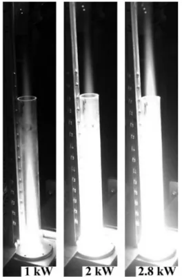
The quartz tube penetrates through the wide waveguide walls, as shown in Fig. 1. The ignitors not shown in Fig. 1 with their terminal electrodes inside the discharge tube are often fired to initiate the plasma generation. The plasma generated inside the discharge tube is stabilized by injecting a swirl gas, which enters the discharge tube sideways, creating a vortex flow in the tube, stabilizing the torch flame in the center of the tube, keeping the torch flame of 5,000

o

C off the discharge tube wall and protecting the wall from torch heat. The temperature profiles are almost flat out to the largest measurable plasma radius of 10 mm with a maximum value of 6000 K ± 200 K on axis. The flame temperature at the 10 mm radius is still 80% of its value on axis. The typical electron density n

e

for argon torch is about 5.0 to 8.0 ( × 10

14

cm

−3

). It depends on the gas flow rate, but not on microwave power. An increase of microwave power brought about an expansion of the plasma flame and increase of the gas temperature with little change in the electron density. However, the electron density increases as the gas flow rate increases in this particular experiment, where the flow rate is a several litters per minute (lpm) or more.

3. Steam microwave plasma torch In this section, we present a pure steam plasma torch powered by microwave. The composition of microwave system components is same with that shown in Fig. 1. For generating a pure steam microwave plasma, we employed a commercially available steam generator originally used for carpet cleaning. It produces 25 grams of steam in a minute. The steam temperature at the exit of the steam generator is 160

o

C; however, Fig. 1. Schematic diagram showing the microwave

system components and the plasma torch.

(3)

it cools rapidly and requires additional heating before it enters a discharge tube made of quartz. The steam enters the discharge tube as a swirl gas. The necessary temperature of the steam for ignition of the plasma in the discharge tube must be 150

o

C or higher. Typical examples of steam plasma torches are presented in Fig. 2, in which steam torches are shown inside a quartz tube, 3 cm in diameter and 30 cm in length.

The torch flame becomes longer as the electrical power increases, as expected. The steam plasma torch is very stable and can usually operate for more than two hours until all of the water in the tank of the steam generator is consumed. The flames labeled 2 and 2.8 kW in Fig. 2 have more heat than the 1 kW flame. This heats the quartz tube, which in turn emits its own light, masking the torch flames in the photographs. However, it is possible briefly to observe the torch flame more clearly through the quartz tube using the naked eye. A steam torch is ignited in a quartz tube with a length of 50 cm, and the diameter and length of the flame are measured in terms of the supplied electrical power. The diameter of the flame was measured at the base of the torch just above the waveguide. The flame diameter D and the flame length L increase with the electrical power. It is noted from the measurement of the flame size that the flame volume proportional to D

2

L increases

almost linearly with the electrical power.

Measuring of the gas temperature along the axis of the plasma torch is important for characterization of the steam plasma at the atmospheric pressure. The high gas temperature was estimated by making use of an optical spectrum, where the experimental data of the optical signals were obtained through the optical fiber placed near the specified portion of z in the plasma torch. Here, z represents the distance from the center of torch, where the base of the torch is located inside the waveguide as shown in Fig. 1, designating z = 0 as the center of the flame, which is the middle point in the waveguide. The experimental data in Fig. 3 are the optical emission of the hydroxide molecules from the position of z = 4 cm in the plasma torch. The optical emission data of each portion of the torch flame were digitalized and stored in a computer. The experimental data in Fig. 3 at z = 4 cm are an example of the optical emission of

OH radicals, which is related to the rotational structure of diatomic gases providing information regarding the rotational temperature. Molecules in the rotational states and the neutral gas molecules are in the thermal equilibrium due to the low energies needed for rotational excitation and the short transition times.

Therefore, the gas temperature can be obtained from the rotational temperature

6)

.

The profile of simulated optical emissions of OH radicals around 309 nm was compared with the experimental emission data, while estimating the gas temperature T . Shown in Fig. 4 is the measured data of the flame temperature T versus the axial distance z

Fig. 2. Typical steam plasma torches operating inside a quartz tube with 3 cm diameter and 30 cm length. The torches are powered by 1, 2, and

Fig. 3. Profiles of simulated optical emission of OH

radicals around 309 nm represented by the solid

curve in comparison with the experimental

emission data (open circles), estimating the gas

temperature to be T = 5000 K.

(4)

from the center for the 2 kW plasma flame similar to the flame labeled as 2 kW in Fig. 2. The flame temperature up to T = 2000 K can be measured by making use of a thermocouple device. In contrast, a flame temperature higher than T = 2000 K is measured by optical spectroscopy, as mentioned above. It is clear from Fig. 2 that there are two distinctive regions of the steam torch flame; a high-temperature zone and a relatively low-temperature zone. The torch flame of the high-temperature zone ranging from z = 0 to z = 10 cm is white and bright, as it is the typical emission of a high-temperature plasma. This can be seen in the flame photograph labeled as 1 kW in Fig. 2. Additionally, the flame color of parts of the low-temperature zone beyond z = 10 cm becomes reddish, characterizing hydrogen burning in oxygen.

A high-temperature steam torch may have a potential application of the hydrocarbon fuel reforming at one atmospheric pressure. As an example, we consider the reforming of methane according to 2H

2

O + CH

4

→ CO

2

+ 4H

2

. The enthalpy and entropy changes due to this reaction can be calculated from data in a table

7)

to be ∆H = 165 kJ/mole and ∆S = 172.4 J/

mole, respectively. The Gibbs free energy of the reaction is given by G = ∆H − T∆S and therefore the reaction temperature of the reforming is calculated to be T = ∆H / ∆S = 957 K. The temperature of the steam plasma torch shown in Fig. 2 is much higher than the reaction temperature T = 957 K in most of the torch flame at the atmospheric pressure. Moreover, the radicals including hydrogen, oxygen and hydroxide molecules are abundantly available in the steam torch, dramatically enhancing the reaction speed. The methane may also breakdown at high temperatures.

On the other hand, methane reforming in a conventional

4. Microwave plasma burner The main parts of experimental configuration for the microwave plasma burner, as shown schematically in Fig. 5, consist of the microwave plasma torch and a fuel-injector. The microwave plasma torch is generated by a 2.45 GHz magnetron, a directional coupler, a 3-stub tuner, a tapered waveguide, and a plasma reactor, as shown in Fig. 1. The microwaves generated from the magnetron passes through the directional coupler and the 3-stub tuner, is guided through the WR340 rectangular tapered waveguide, and enters a quartz tube, as shown in Fig. 5. The quartz tube (outer diameter of 30 mm, thickness of 1.5 mm) was inserted only in the microwave-driven region and was located one-quarter wavelength from the shorted end of the waveguide where the induced electric field is peaked before the plasma initiated and is perpendicular to the wide waveguide walls.

Once the plasma is initiated, the microwaves are dumped directly into the absorbing plasma obstruction.

The electric field induced by the microwave radiation in the quartz tube can be maximized by adjusting the 3-stub tuner. Also, the reflected power adjusted by the 3-stub tuner is almost zero. Even with all the tuning stubs completely withdrawn, reflected power is typically less than 10% of forward power. The forward and reflected powers are monitored by the directional coupler. The microwave plasma is ignited Fig. 4. The measured data of the flame temperature T

versus the axial distance z from the center for the plasma flame at 2 kW.

Fig. 5. Schematic illustration of a microwave plasma

burner system.

(5)

by an external electric-spark system or by inserting a tungsten wire into the quartz tube in the waveguide and sparking in it. The plasma generated inside the quarts tube is stabilized by a swirl gas input. The swirl gas enters the microwave plasma torch via four small holes in tangential direction of inner surface of the quartz tube, as shown in Fig. 5. Therefore, the swirl gas creates a vortex flow in the discharge tube, stabilizing the torch flame in the center of the tube, and keeping the torch flame off the discharge tube walls. Air, oxygen or a mixture of air and oxygen can be used as a swirl gas. Therefore, the swirl gas provides atomic oxygen and molecular singlet oxygen of high-density for near perfect combustion of hydrocarbon fuels, which are injected from the fuel injector in Fig. 5. The fuel injector in Fig. 5 is installed to the stainless steel tube and provides fuel for plasma. The stainless steel tube has the same inner size as the discharge tube and is installed on the tapered waveguide to sustain a steady vortex flow of the swirl gas. Hydrocarbon fuels injected into plasma are mixed with the swirl gas and then the burner flame expands to open air

8)

.

Fig. 6 shows the microwave plasma-burner flames (a) before and (b) after the fuel injection at the applied microwave power of 1.5 kW. In Figs. 6(a) and (b), a mixture of 50 lpm air and 10 lpm oxygen as a swirl gas was injected into the microwave plasma torch, while 50 lpm air as a swirl gas and 10 lpm oxygen with a fuel through the fuel injector were injected in Fig. 6(c). Fig. 6(a) is a picture of the plasma torch flame without fuel injection. The flame was not expanded to the exit of the stainless steel tube of 10 cm in length. However, as shown in Figs.

6(b) and (c), the burner flame shot out through the exit of the stainless steel tube when 0.025 lpm kerosene was injected as a fuel into the microwave plasma torch. The burner flame diameter and length from the

flame exit were about 8 cm and 40 cm, respectively.

The liquid kerosene is evaporated instantaneously by the plasma column with its center temperature of about 6000 K inside the waveguide excitation region at 28 lpm swirl airflow and 1.4 kW microwave power, and burns immediately with oxygen. Actually, the fuel injector in this work was installed just above the waveguide and was 2 cm away from the waveguide excitation region. When 10 lpm oxygen gas was added to the microwave plasma torch, not shown in Fig. 6, it was observed that the plasma flame color changed from a yellowish white to a bluish white, showing the phenomenon of perfect combustion. We expect that the microwave plasma-burner can be used for bulky treatment of waste gas streams and for thermal sources such as incineration and thermal wind drying, etc.

5. Remediation of contaminated soils In this section, we briefly report the soil remediation by making use of the microwave plasma burner Fig. 6. Microwave plasma-burner flames before (a) and after (b and c) a fuel injection at the applied microwave power of 1.5 kW. A mixture of 50 lpm air and 10 lpm oxygen as a swirl gas was injected into the microwave plasma torch in (a) and (b), while 50 lpm air as a swirl gas and 10 lpm oxygen with a fuel through the fuel injector were injected in (c).

Fig. 7. Schematic illustration of soil remediation by the

microwave plasma burner. This is an underway

research in the division of applied technology

research of NFRI .

(6)

blades installed inside the reactor provide enough reaction-time and uniform treatment by delaying transfer of contaminated soil. In the present, we carry out the laboratory test for treating 300 kg/hr of contaminated soil.

6. Conclusions

We reported a high-temperature steam microwave plasma torch, which has a potential application of the hydrocarbon fuel reforming and gasification at one atmospheric pressure. Also, we investigated a high- temperature, large-volume plasma burner. Eventually, we expect that the microwave plasma torch can be used as a tool for producing syn-gas and for eliminating pollutants.

4. Hong, Y. C., Cho, S. C., Bang, C. W., Shin, D.

H., Kim, J. H., Uhm, H. S., Yi, W. J., Appl. Phys.

Lett., 88 (2006) 201502.

5. Kim, J. H., Hong, Y. C., Kim, H. S., Uhm, H. S., J. Korean Phys. Soc., 42 (2003) S876.

6. Moon, S. Y., Choe, W., Spectrochim. Acta, Part B, 58 (2003) 249.

7. Lide, D. R., CRC Hand Book of Chemistry and Physics , (Taylor and Francis, N. Y.), Chap.5, (2005).

8. Bang, C. W., Hong, Y. C., Cho, S. C., Uhm, H.

S., Yi, W. J., IEEE Trans. Plasma Sci., 34 (2006)

1751.

수치

Fig. 1 shows a schematic view of the atmospheric microwave plasma system. It consists of the 2.45 GHz microwave generator, WR-340 waveguide  com-ponents, including an isolator, a directional coupler, and a 3-stub tuner, and a microwave plasma torch as a fi
Fig. 3. Profiles of simulated optical emission of OH radicals around 309 nm represented by the solid curve in comparison with the experimental emission data (open circles), estimating the gas temperature to be T = 5000 K.
Fig. 5. Schematic illustration of a microwave plasma burner system.
Fig. 6 shows the microwave plasma-burner flames (a) before and (b) after the fuel injection at the applied microwave power of 1.5 kW

참조

관련 문서

Schematic shape and technical drawing of the prototype GS type jellyfish separator system used in the CWC experiment.. Schematic shape and technical drawing

As a result, in order to form a cooperation system for the regulation of shipment and production by structuring a network centering on Zakmokban

In particular, the Basic Electric Power Supply and Demand Plan shows only the generation of low and intermediate level radioactive wastes in units of 10 years,

• Principle of work and energy can be applied to the entire system by adding the kinetic energies of all particles and considering the work done by all external and

Reference 7 contains a derivation (also by the Newtonian method) of a system of nonlinear equations for the elastic bending and rigid pitching motion of a cantilever rotor

A study on development of outfitting modeling and automatic creating drawing system by AVEVA Marine..

plasma is treated as a single hydrodynamic fluid acted upon by electric and

à We note that there are three unknown parallel forces acting on the bar in Fig. ii) By substituting (a) into (c), obtain all the deflections in terms of