http://dx.doi.org/10.7839/ksfc.2018.15.3.001
Time-Delay Control for the Implementation of the Optimal Walking Trajectory of Humanoid Robot
Doo Sung Ahn*
Received: 03 Apr. 2018, Revised: 30 Apr. 2018, Accepted: 11 Jun. 2018
Key Words:Time-Delay Control, Optimal Walking Trajectory, Humanoid Robot, Particle Swarm Optimization
Abstract: Humanoid robots have fascinated many researchers since they appeared decades ago. For the requirement of both accurate tracking control and the safety of physical human-robot interaction, torque control is basically desirable for humanoid robots. Humanoid robots are highly nonlinear, coupled, complex systems, accordingly the calculation of robot model is difficult and even impossible if precise model of the humanoid robots are unknown. Therefore, it is difficult to control using traditional model-based techniques. To realize model-free torque control, time-delay control (TDC) for humanoid robot was proposed with time-delay estimation technique. Using optimal walking trajectory obtained by particle swarm optimization, TDC with proposed scheme is implemented on whole body of a humanoid, not on biped legs even though it is performed by a virtual humanoid robot. The simulation results show the validity of the proposed TDC for humanoid robots.
* Corresponding author: [email protected]
1 Department of Mechanical Design Engineering, Pukyong National University, Pusan 48547, Korea
Copyright Ⓒ 2018, KSFC
This is an Open-Access article distributed under the terms of the Creative Commons Attribution Non-Commercial License(http://
creativecommons.org/licenses/by-nc/3.0) which permits unrestricted non-commercial use, distribution, and reproduction in any medium, provided the original work is properly cited.
Nomenclature
: sagittal angle
: coronal angle ψ : transverse angle
: coordinate of ZMP
: velocity and position of k-th agent
: each agent’s best position
: population’s global best position
: reference trajectory of swing foot
: initial and final time of the i-th segment
: slanted angle of upperbody
: mass of link i
: mass center coordinate of link i
: inertial components of link i
1. Introduction
Since robotic arms appear a half-century ago, the modern robots have been used increasingly in the manufacturing industry and has experienced a rapid expansion, beyond the industrial sector, to other fields of human-being lives. Humanoid robots have fascinated many researchers since the first modern humanoid, WABOT-1 was developed in 19731). Many humanoid robotic platforms have been proposed, e.g., ASIMO, HUBO, and HRP-4C2-4)
Humanoid robots are highly nonlinear, coupled, complex systems5). The tracking control of walking trajectories for humanoid robot is one of the most challenging problems. Accurate dynamic model of a humanoid robot is required to realize high accuracy-tracking control with model-based controllers6). The nonlinear models of humanoid robots are complex to calculate correctly, and even impossible if models of the humanoid robots are unknown. Therefore, it is difficult to control using traditional model-based techniques. Also, conventional humanoid robots have
stiff joints with high-ratio speed reducers. Accurate trajectory tracking can be achieved with these robots;
however, they are too stiff to share workspaces with humans. To bring the humanoid robots into the unstructured human living environment as assistant robots or coworkers, the robots should be intrinsically safe for physical human–robot interaction. Therefore torque control are basically required for the safety of human–robot interaction.
To realize model-free torque control, time-delay estimation (TDE) technique was presented for control of robot manipulators in the late 1980s7). The TDE technique is simple, efficient, and yet effective. The TDE technique assumes that the nonlinear function does not move much for a sufficiently small time, and estimation and cancelation are performed through the TDE using time-delayed information of control inputs and state derivatives. The so-called time-delay control (TDC) for robot manipulators was presented with this technique8). The key idea of the TDC is canceling unknown nonlinear robot dynamics and injecting the desired error dynamics. It has been applied to robot manipulators to accomplish trajectory tracking control, impedance control, force control, and dual arm cooperative control9-12). Particularly, it has been also implemented for humanoid robots although it was only biped legs, not a whole body13).
In this paper, TDC with proposed scheme is implemented on whole body of a humanoid, not on biped legs, even though it is performed by a virtual humanoid robot. The optimal walking trajectory obtained from particle swarm optimization (PSO) is used for reference trajectory for TDC of humanoid robots. The TDC for humanoid robots consists of two elements: the robot dynamics canceling element through the TDE, and the desired error dynamics element.
Mostly, the TDE is calculated from one-sample time delayed information.
The remainder of this paper is organized as follows.
In Section 2, a high-accuracy tracking control of humanoid robots is proposed based on TDC. Section 3 presents the optimal walking trajectory of a humanoid robot using PSO. In Section 4, the proposed controller is compared with PID based controllers by simulation
of optimal walking trajectory of a full-size, virtual humanoid robot. Finally, conclusions are given.
2. TDC for a Humanoid Robot
The standard form of the dynamic equations of a humanoid robot is as follows:
(1)
where q qq show the position, velocity, and acceleration of the joints, respectively, and M q
stands for the generalized inertia matrix, C q q
the Coriolis/centripetal matrix, G q the gravitational vector, F q q the friction forces,
the disturbance torques, and the joint torques.
Introducing a positive diagonal matrix, M, one can obtain another expression of (1) as follows.
(2)
where
(3)
The control objective is to make a robot position q follow the reference input trajectory qd. To this end, let us define e qd q, e qd q and e qd q.
The desired error dynamics is defined by
(4)
where KD , and KP are constant diagonal gain matrices. KD is a derivative gain and KP is a proportional gain.
The control input can be picked as
(5)
where
(6)
Here Nq q q can be estimated by the TDE, as
(7)
where Nq q q denotes the estimate of Nq q q,
*t-L is time-delayed value of *, and L is the delay of estimation time, which is normally the sampling period in digital implementation.
From (2), one can obtain
(8)
Thus, with the equations of (5)-(8), the TDC law for a humanoid robot is expressed by
(9)
Substituting the control input (8) and (9) into humanoid robot dynamics (2) yields the closed-loop dynamics, as
(10)
If identity of N Nt L assumed, the closed loop equation becomes (4), the desired error dynamics. The well-known stability condition for the TDC is established by Youcef-Toumi8) and Hsia7) independently, expressed by
(11)
When the closed loop system is stable using the stability condition (11), the N Nt L is bounded because N is sum of continuous terms and bounded discontinuous terms. The bounded TDE error ε is defined as
(12)
Then the closed loop system dynamics with the TDC (9) becomes
(13)
The TDE error ε is closed to 0 in most of operating time of humanoid robot unless it exhibits a pulse-type error caused from discontinuity of Coulomb friction at velocity reversal13).
Fig. 1 shows the block diagram of the TDC applied to a humanoid robot.
Fig. 1 Block diagram of the TDC for humanoid robot control
3. Optimal walking trajectory of humanoid robot
3.1 Blending polynomial
For a natural walking, the leg joints need to revolve in a smooth and seamless way. For this cause, blending polynomial (BP) was adopted to denote joint angle trajectories, which uses a cubic polynomial as each segment. A blending polynomial includes more than two segments, which are represented by cubic polynomials associated with conditions at via points. Since most of trajectories represent effectively these conditions, BP’s are adopted for describing the joint trajectory. Joint angle trajectories in the i-th segment of BP are denoted with the following cubic polynomial function:
(14)
where the four coefficients are calculated from specified boundary conditions such as the initial and final angular positions/velocities of the i-th segment.
3.2 Particle swarm optimization
PSO14) is a global optimization method inspired by the social activities of herds of birds and schools of fish, which frequently share their information on
messages and food. The basic principle of PSO supports that a herd of birds communicates with not only their best-so-far individual information but also the up-to-date global best information, whose equations are written as below:
(15)
where and show the current position and velocity vector of the k-th agent, while and
are the next position and velocity vectors calculated after iterations based on each agent’s the population’s global best position vector and best position vector . The coefficients , and w represent two weight factors associated with the search history and inertial weight, respectively. and are between 0 and 1 random numbers uniformly distributed.
3.3 Optimization of Joint angle trajectory15-16) Because the number of parameter to be optimized are so many, they must be reduced to get precise parameters efficiently using PSO. For the natural and stable walking, the following conditions about walking posture should be satisfied:
Walking Condition 1: Upper-body must be maintained to vertical both in the sagittal plane and in the coronal plane.
(16)
where the subscripts stand for ankle, knee and hip and the superscripts represent left and right foot, respectively.
Walking Condition 2: The swing leg should be parallel to supporting leg in order to keep natural walking.
(17)
Walking Condition 3: The swing foot during walking should be parallel to and above ground in order to decrease riskiness that the toe or heel of the swing foot bump into ground.
(18)
In order to make stable biped walking, cost function is designed as follows
(19)
where wa, wh and represent weighting factors of Cost Conditions, respectively.
Cost Condition 1: Angles of both knees always should keep positive in order to avoid possible damage of joints and disgusting movement of legs and arms.
(20)
Cost Condition 2: Swing foot should keep tracking the reference trajectory in the sagittal and coronal plane for the stable step.
(21)
where , , , , represents sampling time, i-th sampling time, total number of sampling, initial and final x-coordinates and of swing foot, respectively.
Cost Condition 3: Reference trajectory of ZMP should be located in the sole area for the stability of biped humanoid robot.
(22)
where , , , and represents x and y coordinates of stable ZMP domain, length and width of stable ZMP domain, respectively
4. Simulation
4.1 Set up
For the walking simulations of a humanoid robot, a virtual humanoid robot is used. This is first designed by Solidworks17), as shown in Fig. 2, which is based on DARWIN-OP robot made by Robot is Ltd18). Then it is transformed into a virtual humanoid robot in the Simscape19) environment. The humanoid robot is 45cm tall, weighs 2.8kg, and has 20 DOF. It has 11 DOF in the sagittal plane, 3 DOF in the transverse plane and 6 DOF In the coronal plane. The center of mass is positioned in the center of its pelvis. The position is optimal for proper balancing and adequate distribution of inertia moment during gait.
Fig. 2 Original humanoid robot (DARWIN-OP) and virtual humanoid robot made by Simscape
Fig. 3 presents the schematic diagram of TDC implemented in left ankle joint of sagittal plane under Simscape environment. The Mux block combines its inputs into a single vector output. The Demux block extracts the components of an input signal and outputs the components as separate signals.
The S-PS Converter block converts a non-physical signal into a physical signal or vice versa. The Delay block holds and delays its input by one major integration time step. Feedback signal section detects position, velocity, and acceleration by sensors attached to joints and compared to reference signals from optimal trajectory section.
Fig. 3 Schematic diagram of TDC implemented in left ankle joint of sagittal plane
4.2 Simulation
In this section, the performance of the proposed TDC is verified, through 3D simulations in Simscape virtual environment, comparing with traditional PID control.
The step length is 5 cm and upper-body keeps vertical during walking. Biped walking trajectory begins from left foot-supported position and ends in right foot-supported position. The spring stiffness and damping coefficient of left ankle joint in sagittal plane are given 10 N*m/rad and 0.1 N*m/(rad/s) respectively.
The proportional and derivative gain, KD, KP and
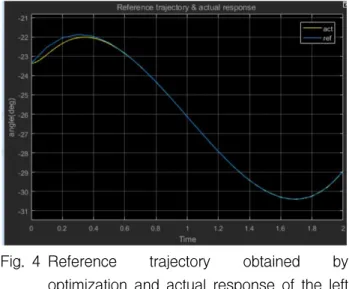
M are set to 100, 20, and 20, respectively, after a process of trial and error. Fig. 4 shows the reference trajectory obtained by PSO presented in Section 3 and actual response of the left ankle in sagittal plane with TDC. Fig. 5 and Fig. 6 represents the tracking error and input torque of left ankle joint in sagittal plane
Fig. 4 Reference trajectory obtained by optimization and actual response of the left ankle in sagittal plane with TDC
Fig. 5 Tracking error of left ankle joint in sagittal plane when proposed TDC is implemented
Fig. 6 nput torque of left ankle joint in sagittal plane with TDC
Fig. 7 Tracking error of left ankle joint in sagittal plane when traditional PID control is implemented without TDC
Fig. 8 Successive 3D view of humanoid robot in biped walking
with TDC, respectively. Fig. 7 shows the tracking error of left ankle joint in sagittal plane when only traditional PID control is implemented without TDC. Fig. 8 shows the successive 3D view of humanoid robot in biped walking when the left foot is supported.
5. Conclusion
For the requirement of both accurate tracking control and the safety of physical human-robot interaction, torque control is basically desirable for humanoid robots. Humanoid robots are highly nonlinear, coupled, complex systems, accordingly the calculation of robot model is difficult and even impossible if precise models of the humanoid robots are unknown. Therefore, it is difficult to control using traditional model-based techniques. To realize model-free torque control, TDC for humanoid robot was proposed with TDE technique.
The TDC for humanoid robots consists of two elements: the robot dynamics canceling element using the TDE, and the desired error dynamics injecting element. TDE is computed from one-sample time delayed information. Using optimal walking trajectory obtained by PSO, TDC with proposed scheme is implemented on whole body of a humanoid, not on biped legs. The simulation results are presented to show the validity of the proposed TDC for humanoid robots.
References
1) J. Yamaguchi, E. Soga, S. Inoue, and A. Takanishi,
“Development of a bipedal humanoid robot-control method of whole body cooperative dynamic biped walking,” in Proc. IEEE Int. Conf. Robot. Autom., pp. 368–374, 1999.
2) K. Hirai, M. Hirose, Y. Haikawa, and T. Takenaka,
“The development of Honda humanoid robot,” in Proc. IEEE Int. Conf. Robot. Autom., Vol. 2, pp.
1321–1326, 1998.
3) I.-W. Park, J.-Y. Kim, J. Lee, and J.-H. Oh,
“Mechanical design of the humanoid robot platform, HUBO,” Adv. Robot., Vol. 21, No. 11, pp. 1305–
1322, 2007.
4) K. Kaneko “Hardware improvement of cybernetic human HRP-4C for entertainment use,” in Proc.
IEEE/RSJ Int. Conf. Intell. Robots Syst., pp. 4392–
4399, 2011.
5) G. Zidani, S. Drid, L. Chrifi-Alaoui, D. Arar, and P.
Bussy, “Robust nonlinear control of a mobile robot,”
JEET, Vol. 11, No. 4, pp. 1012-1019, 2016.
6) M. Uebel, I. Minis, and K. Cleary, “Improved computed torque control for industrial robots,” Proc.
IEEE Int. Conf. Robot. Autom., Vol. 1, pp. 528-553, 1992.
7) T. C. Hsia, “A new technique for robust control of servo systems,” IEEE Trans. Ind. Electron., Vol. 36, No. 1, pp. 1-7, 1989.
8) K. Youcef-Toumi and O. Ito, “A time delay controller for systems with unknown dynamics,”
Trans. ASME J. Dyn. Syst. Meas. Control, Vol. 112, No. 1, pp. 133-142, 1990.
9) S. Jung, T. Hsia, and R. Bonitz, “Force tracking
impedance control of robot manipulators under unknown environment,” IEEE Trans. Control Syst.
Technol., Vol. 12, No. 3, pp. 474-483, 2004.
10) H. J. Bae, M. Jin, J. Suh, J. Y. Lee, P. H. Chang, and D. S. Ahn, “Control of robot manipulators using time-delay estimation and fuzzy logic systems,” J. Electr. Eng. Technol. Vol. 12, No. 3 pp. 1271-1279, 2017.
11) M. Jin, J. Lee, P. H. Chang, and C. Choi,
“Practical nonsingular terminal sliding-mode control of robot manipulators for high-accuracy tracking control,” IEEE Tran. Ind. Electron., Vol. 56, No. 9, pp. 1406-1414, 2009.
12) S. H. Park, E. I. Jeong and D. G. Shin,
"Identification of the Relationship Between the Discrete TDCIM and the Discrete PID Controller", J. Drive and Control, Vol.14, No.4, pp.23-28, 2017 13) M. Jin, J. Lee, and N. G. Tsagarakis, “Model-free
robust adaptive control of humanoid robots with flexible joints”, IEEE Tran. Ind. Electron., Vol. 64, No. 2, pp. 1706-1715, 2017
14) J. Kennedy, and R. Eberhart, "Particle Swarm Optimization," IEEE Int. Conf. on Neural Network, Vol.4, pp. 1942-1948, 1995
15) D. S. Ahn, “Biped Walking of a Humanoid Robot for Argentina Tango,” J. Drive and Control, Vol.
13, No. 4 pp. 52-58, 2016.
16) J. W. Kim, Humanoid Robot Robotis OP, Hong Reung Scientific Publishing Co., Seoul, pp.
366-382, 2015
17) http://www.solidworks.co.kr 18) http://www.robotis.com 19) http://www.mathworks.co.kr