• 검색 결과가 없습니다.

Computational Analysis of the Effects of Spray Parameters and Piston Shape on Syngas-Diesel Dual-Fuel Engine Combustion Process

N/A
N/A
Protected

Academic year: 2021

Share "Computational Analysis of the Effects of Spray Parameters and Piston Shape on Syngas-Diesel Dual-Fuel Engine Combustion Process"

Copied!
13
0
0

로드 중.... (전체 텍스트 보기)

전체 글

(1)

Computational Analysis of the Effects of Spray Parameters and Piston Shape on Syngas-Diesel Dual-Fuel Engine Combustion Process

Abubaker Ahmed M. M. Ali

*

, Ali Kabbir

*

, Changup Kim

**

, Yonggyu Lee

**

, Seungmook Oh

**

and Kim Ki-seong

*,†

Key Words: Low calorific value syngas, Dual-fuel engine, 3D CFD analysis, Chemical kinetics, Injection parameters, Piston shape

Abstract

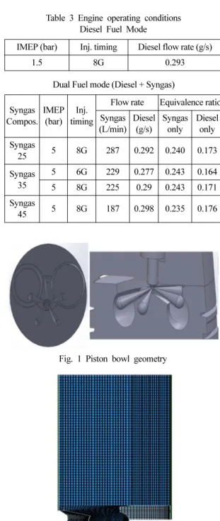
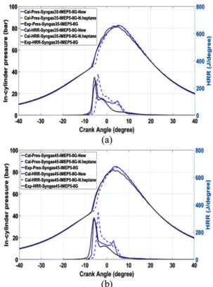
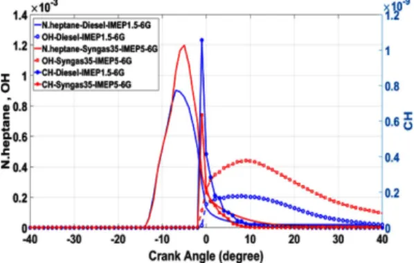
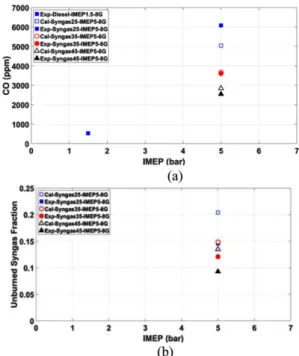
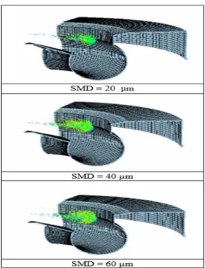
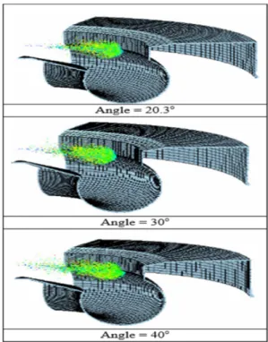
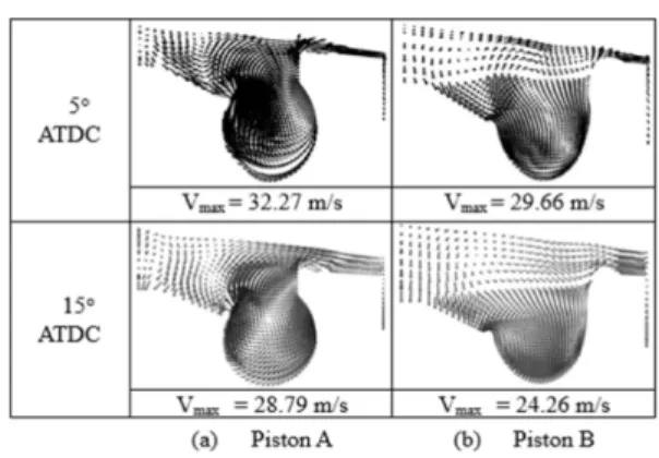
In this study, a 3D CFD analysis method for the combustion process was established for a low calorific value syngas- diesel dual-fuel engine operating under very lean fuel-air mixture condition. Also, the accuracy of computational analysis was evaluated by comparing the experimental results with the computed ones. To simulate the combustion for the dual- fuel engine, a new dual-fuel chemical kinetics set was used that was constituted by merging two verified chemical kinetic sets: n-heptane (173 species) for diesel and Gri-mech 3.0 (53 species) for syngas. For dual-fuel mode operations, the early stage of combustion was dominated by the fuel burning inside or near the spray plume. After which, the flame propagated into the syngas in the piston bowl and then proceeded toward the syngas in the squish zone. With the baseline injection system and piston shape, a significant amount of unburned syngas was discharged. To solve this problem, effects of the injection parameters and piston shape on combustion characteristics were analyzed by calculation. The change in injection variables toward increasing the spray plume volume or the penetration length were effective to cause fast burning in the vicinity of TDC by widening the spatial distribution of diesel acting as a seed of auto-ignition. As a result, the unburned syngas fraction was reduced. Changing the piston shape with the shallow depth of the piston bowl and 20% squish area ratio had a significant effect on the combustion pattern and lessened the unburned syngas fraction by half.

1. Introduction

In the remote areas where coal is produced, com- mercialization of small-sized complex power plants producing electricity and Coal to Liquid fuel (CTL) from coal can be a good way of solving local energy problems.

These complex power plants first produce syngas

by gasifying the coal. The syngas consists mainly of carbon monoxide, hydrogen, small quantities of methane, and other diluents such as nitrogen and car- bon dioxide.

Air or oxygen is used as gasification agents for entrained-flow gasifiers that supply coal in the form of Coal Water Mixture (CWM). When air is used, the syngas produced contains a considerable amount of nitrogen. The syngas, which has undergone a cleaning process, is converted to a hydrocarbon con- densate through the Fisher-Tropsch synthesis process and the off-gas of very low calorific value is dis- charged.

The off-gas mixed with syngas at the proper ratio (in this study, it is called syngas) has a very low cal- orific value and can be used as a fuel to drive recip- rocating engines for power plants.

(Recieved: 28 Oct 2018, Recieved in revised form: 21 Dec 2018, Accepted: 22 Dec 2018)

*

Department of Mechanical Design Engineering, Chonnam National University, Yeosu 550-749, Korea

**

Green Power Laboratory, Korea Institute of Machinery &

Materials, 171 Jang-dong, Yuseong-gu, Daejeon, Korea

Dept. of Mechanical Design Engineering 50 Daehak-ro, Yeosu, Jeonnam

E-mail : [email protected]

TEL (061)659-7286 FAX : (061)659-7289

(2)

Hydrogen and carbon monoxide, which are the main components of this syngas and have high auto- ignition temperatures, are suitable for the fuel of dual-fuel engines in which a small amount of diesel is injected as an ignition source.

This dual-fuel engine has the advantage of achiev- ing high thermal efficiency due to high compression ratio and lean combustion.

Many researchers analyzed combustion character- istics using various gaseous fuels such as syngas, nat- ural gas, and biogas as a fuel for dual-fuel engines and reported low NOx emission and high thermal efficiency

(1-5)

. Some researchers

(6-8)

reported the com- bustion characteristics of the supercharged syngas engine, using a pilot injection of diesel fuel.

Most previous researches were conducted on dual- fuel engines using high calorific value syngas with micro-pilot diesel injection. In this study, syngas was mixed with off-gas, so it has a very low calorific value. To enhance the thermal efficiency of power generating engine, it is necessary to operate under lean condition.

Due to low calorific value and extremely lean opera- tion, high emission of unburned syngas can be a seri- ous problem in the Low calorific value Syngas Lean Burn (LSLB) dual-fuel engine, which leads flame quenching phenomena close to the wall of the com- bustion chamber. Hence, an appropriate dual-fuel combustion tactic is necessary.

In order to overcome the problems of the LSLB dual-fuel engine, the injected amount of diesel should be considerably high for spreading the diesel fuel widely in the combustion chamber using high injec- tion speed. With this method, flames can be initiated in a wide area, which leads to burning most of the fuel near the TDC and flame propagation distances to the remaining region of the combustion chamber can be shortened.

In the LSLB engine, the injected amount of diesel is about 20% of the full load, therefore its shape affecting combustion may be different from that of conventional diesel engines. However, injection param- eters such as mean droplet size, spray cone angle, nozzle hole size, and injection rate have a significant

influence on combustion.

The piston bowl shape is also a crucial parameter in the LSLB engine where flame propagation must occur in the lean syngas-air mixture condition, since it greatly influences the flow field and flame propa- gation in the combustion chamber near the TDC.

The reliability of the analysis method is verified by performing engine tests in the baseline conditions, then using 3D CFD analysis for the LSLB engine can be an effective way to evaluate the effect of injection parameters and piston bowl shape on com- bustion.

For a reliable 3D CFD analysis, chemical kinetics set is absolutely imperative for both fuels: diesel and syngas due to the similar quantity of diesel and syn- gas. There is need to constitute a new chemical kinetics mechanism that could cover a wide range of chemical reaction for diesel and syngas for combus- tion analysis of LSLB dual-fuel engine.

Therefore, in this study, the combustion character- istics of the LSLB syngas-diesel dual fuel engine were analyzed using 3D CFD. In this analysis, a chemical kinetics set suitable for the combustion reaction of syngas and diesel was constituted and used. The reliability of the calculation was evaluated by comparing the calculation results to the engine test results. Based on the established analytical meth- ods, the effects of injection variables and piston bowl shape were analyzed computationally.

2. CFD Model and Validation

2.1 Computational models and chemical kinetics The FORTÉ simulation package was used as a computational tool for the LSLB dual-fuel engine.

Syngas was considered to be homogeneously distrib-

uted in the combustion chamber at the start of the

simulation (at IVC). The diesel injection process was

simulated using standard DDM (Droplet Discrete

model), and KH-RT model was used to model atom-

ization and break-up of spray along with NTC colli-

sion model. RNG k-ε was used to model turbulent

flow along with wall function (O’Rourke and Ams-

(3)

den wall heat transfer model), which accounts for the heat transfer through the boundary.

Some chemistry based method solutions were used to enhance the simulation speed in FORTE like built-in sparse-matrix, DCC (dynamic cell cluster- ing). This offers near-linear scaling between CPU time and the number of species with zero loss of accuracy. In addition, DCC technique has also been used to reduce the chemistry-related computational time.

Tables 1-3 list the details of the engine specifica- tions and operating conditions, respectively used in this study. The piston bowl of the engine has a toroi- dal shape, and its center is shifted by 5.9 mm from the cylinder axis. Fig. 1 shows that the injector is mounted at an angle of 8 degrees to the cylinder axis.

Due to the offset of the piston bowl and the tilting of the injector from the cylinder axis, the combustion chamber, including diesel spray, is slightly asymmet- ric, but each nozzle hole of the injector has a differ- ent injection angle targeted at similar heights in the side wall of the piston bowl, so the resulting combus-

tion pattern of each hole might be similar. Therefore, in CFD calculations, the combustion chamber was assumed as axisymmetric.

The effect of the number of meshes on the calcula- tion results was investigated and the computational

Fig. 1 Piston bowl geometry Table 1 Engine specifications

Bore (mm) 123

Stroke (mm) 155

Compression ratio 17.1

Speed (rpm) 1800

Intake valve 18

o

BTDC/34

o

ABDC Exhaust valve 46

o

BBDC/18

o

ATDC Injection pump Zexel in-line “P”

Injection nozzle 5 holes, d

n

= 0.37 mm Needle opening pres. 1

st

: 160 bar, 2

nd

: 220 bar

Injection timing

6G SOI = 13.91

o

BTDC Dur = 5.2

o

8G SOI = 21.40

o

BTDC

Dur = 5.2

o

Table 2 Syngas composition

Syngas25 H

2

:25%, CO:15%,CO

2

:10%, N

2

:50%

Syngas35 H

2

:35%, CO:15%, CO

2

:10%,N

2

:40%

Syngas45 H

2

:45%, CO:15%, CO

2

:10%,N

2

:30%

Table 3 Engine operating conditions Diesel Fuel Mode

IMEP (bar) Inj. timing Diesel flow rate (g/s)

1.5 8G 0.293

Dual Fuel mode (Diesel + Syngas) Syngas

Compos.

IMEP (bar)

Inj.

timing

Flow rate Equivalence ratio Syngas

(L/min) Diesel

(g/s)

Syngas only

Diesel only Syngas

25 5 8G 287 0.292 0.240 0.173

Syngas 35

5 6G 229 0.277 0.243 0.164

5 8G 225 0.29 0.243 0.171

Syngas

45 5 8G 187 0.298 0.235 0.176

Fig. 2 Computational mesh

(4)

mesh represented in Fig. 2 was used for the calcula- tion.

A new dual-fuel chemical kinetics set was consti- tuted by merging two verified chemical kinetics sets;

n-heptane (173 species) and Gri-mech 3.0 for syngas.

N-heptane has a comparable cetane number and combustion characteristics with diesel and it has been accepted as a surrogate for diesel in both experimen- tal and numerical studies

(9-13)

. Generally, Gri-mech 3.0 is an optimized mechanism designed to model natural gas combustion and is composed of 53 spe- cies and 325 reactions.

Figure 3 shows that the simulated pressure and heat release rate were well matched with experimen- tal pressure and heat release rate using the new chemical kinetic set compared to Diesel_comp_173sp. Addi- tionally, CFD model with new chemical kinetic set successfully matched with experimental auto-ignition point and combustion duration. Thus, the new chem-

ical kinetics set was used in this study.

3. Results and Discussion

3.1 Combustion characteristics of the LSLB dual-fuel engine in baseline conditions

A vital feature of the LSLB dual-fuel engine is that it uses syngas which has a low calorific value, and burns in excessively lean mixture conditions as shown in Table 3. To overcome these obstacles in the LSLB dual-fuel engine, the diesel spray plume volume should be much larger than that of a conventional dual-fuel engine. In this study, the diesel injection amount reaches about 20% of that of the full load. This amount of diesel injection through the five nozzle holes is effec- tive in shortening the flame propagation distance in the syngas mixture by spreading the ignition seed of diesel into the combustion chamber deeply and widely in a short time.

Figure 4 shows the combustion chamber pressure and the HRR results of the experiments and calcula- tions when operating in dual-mode and diesel-only mode, while Fig. 5 shows the concentrations of n- heptane, CH and OH radicals during combustion.

The ignition timing and the pattern of the early stage of the combustion with the rapid pressure rise in the dual-fuel mode are almost the same as those in the diesel-only mode, which can be characterized as the phenomena in the premixed combustion phase in the

Fig. 3 Experimental and numerical comparison of the in- cylinder pressure and HRR of syngas-diesel dual-fuel mode using new mechanism and n-heptane chem- ical kinetics set.

Fig. 4 Comparison of Experimental and numerical in-cyl-

inder pressure and HRR of diesel only and dual-

fuel mode

(5)

four stages of diesel spray combustion, i.e., ignition delay, premixed combustion, mixing-controlled com- bustion, and late combustion. In the combustion chamber during the premixed combustion phase, a large portion of fuel that has been evaporated from droplets and mixed with air during the ignition delay period burns rapidly, and causes an abrupt increase of the pressure. The auto-ignition of the LSLB dual-fuel engine depends solely on diesel, because the auto- ignition temperatures of hydrogen and carbon mon- oxide are as high as 585°C and 605°C, respectively, at atmospheric pressure. The HRR pattern, which occurs during the mixing-controlled combustion phase of a typical diesel spray combustion, is not evident in Fig. 4, because the amount of diesel fuel is too small i.e. about 20% of that of the full load in this engine operating conditions.

Also, for both operating conditions, the concentra- tions of CH radicals increase, and then decrease in almost the same form after ignition; but in the case of the dual-fuel mode, it is reduced in a shorter period. This is because the components of syngas, especially hydrogen with high laminar flame speed, within the diesel spray plume has contributed to the rapid burning of diesel fuel. In the previous study of the diesel combustion process conducted by measur- ing chemi-luminescence, CH radicals start to appear at the cool flame stage and continued to exist during combustion

(14)

. Therefore, the presence of CH radi- cals indicate that the burning of the hydrocarbon fuel is in progress; otherwise, it means that the hydrocarbon

fuel is exhausted. OH radicals start to appear right after the appearance of CH radicals, and increase until the instance of the rapid drop of the CH radi- cals. When the CH radicals are almost depleted, the concentration of the OH radical reaches the peak, and then gradually decreases. OH radical form in the hot flame zone of hydrocarbons and are also gener- ated as an essential role as an intermediate during the combustion process of hydrogen

(14)

.

The OH radical after depletion of the CH radical might have originated from the flame zone of hydro- gen. In hydrogen combustion, the following elementary chemical reactions are the sources of OH radicals

(15,16)

:

O

2

+ H = OH + O (1)

H

2

+ O = OH + H (2)

H + O

2

(+M) = HO

2

(+M) (3) HO

2

+ H = OH + OH (4) Figure 5 shows that when the flame propagates into the syngas region in the piston bowl after the rapid combustion of the diesel fuel, the amount of OH radical maintains its peak value, due to the wide flame area in the piston bowl, while Fig. 6 shows the amount gradually decreases as the flame propagates into the squish area. The sequential images in Fig. 6 show the temperature distributions in the combustion Fig. 5 Comparison between the molar fraction of n-Hep-

tane, OH, and CH with changes in crank angle

Fig. 6 In-cylinder temperature distribution at Syngas35,

IMEP5, and 6G

(6)

chamber.

Figure 7 shows that because the squish area of the target engine is about 30% of the total piston area, during the compression process a strong squish flow from the squish area to the piston bowl is generated, and in the expansion process, a strong reverse squish flow is generated in the opposite direction.

In the LSLB dual-fuel engine, the fuel-air mixture in the squish zone is almost composed of just syngas and air, so the equivalence ratio of this mixture is extremely low; hence the flame propagation speed is low. Therefore, it can be expected that it takes longer time for the flame to arrive at the cylinder wall. But it is apparent in Fig. 4 and the sequential images of the temperature distribution in Fig. 6 that the flame arrives at the cylinder wall faster than expected. The reason for this phenomenon is the reverse squish flow, which is strongly formed in the squish region during the expansion process. The 15º ATDC veloc- ity distribution in Fig. 7 shows that the maximum velocity of the reverse squish flow reaches 29 m/s, which is 100 times greater than the laminar flame speed, which determines the speed at which the flame front moves in the squish area.

In the squish zone, the fuel is almost syngas. Thus, like Spark Ignition (SI) engines, the flame propaga- tion in the turbulent premixed mixture is the combus- tion mechanism. Since the mixture is extremely lean, and H

2

and CO in syngas have high auto-ignition temperature, flame quenching may occur earlier and near the combustion chamber wall during the flame propagation, which causes high CO emission repre- sented in Fig. 8.

3.2 Effects of injection parameters

In the LSLB engine, the injected amount of diesel is about 20% of the full load, and flame propagates through the syngas-air mixture after burning of diesel spray plume, so the influence of injection parameters on combustion in LSLB engine may be different from that in conventional diesel engines.

The injection parameters such as mean droplet size, spray cone angle, nozzle hole size, and injection rate can determine the diesel spray plume volume and the spray penetration length, which has a signifi- cant influence on the combustion, as the components of syngas existing in the diesel spray plume during the combustion of the diesel fuel, especially the hydrogen with high flame velocity, makes the burn- ing more active.

All components of the injection system, including the two-spring injector, as shown in Table 1 were ini- tially used in a power-driven diesel engine before ret- rofitting as the test engine in this study. The nozzle- hole diameter was 0.37 mm and the needle opening pressures of the two springs were 160 bar and 220 bar, respectively. In the engine test and the computa- Fig. 7 Velocity vector plot at Syngas35, IMEP5, and 6G

(center plane of the 72

o

sector mesh)

Fig. 8 CO emission and unburned syngas fraction at

IMEP 5 bar

(7)

tional analysis carried out using the baseline injection system, a significant amount of syngas was dis- charged without burning. To alleviate this problem, it is necessary to modify the injection parameters and the piston bowl shape were initially optimized for a diesel engine to suit syngas-diesel dual fuel engine.

To find appropriate ways of improving the unburned syngas emission problem, the effects of the injection parameters such as mean droplet size, spray cone

angle, and injection rate on combustion were compu- tationally analyzed.

The calculation results when the SMD of the spray was changed to 20 μm, 40 μm, and 60 μm were rep- resented as shown in Fig. 9. During the initial stage of combustion, as the SMD increased, the pressure rise rate and HRR also increased which was consid- ered to be caused by the increase in the spray plume volume and the penetration length. This phenomenon can be shown in the spray behavior as shown in Fig. 10, which illustrates that as the SMD increases, the pen- etration length becomes longer and the spray plume

Fig. 9 Comparison of the in-cylinder pressure and HRR of dual-fuel mode at a different SMD

Fig. 10 Diesel spray penetration for syngas45, IMEP5, and 8G at a different SMD

Fig. 11 Velocity vector plot at Syngas45, IMEP5, and 8 G (center plane of the 72

o

sector mesh)

Fig. 12 CO emissions and unburned syngas fraction at a

different SMD

(8)

volume also increases. As represented in Fig. 11 which shows the flow field distribution in the com- bustion chamber at the end of the compression pro- cess, a strong squish flow is formed in the opposite direction of spray, which interferes with the penetra- tion of the spray. The larger the SMD, the larger the momentum is believed to have favored the penetra- tion. Unburned syngas fraction was reduced by 2%

when larger SMD particles were used compared to smaller SMD particles as shown in Fig. 12.

For a conventional nozzle hole, the spray cone angle is determined by the geometric aspect ratio of the nozzle, the pressure difference across the nozzle, and the density ratio, as shown in Eq. (5)

(17)

.

(5)

Where is nozzle length to diameter ratio, is nozzle hole diameter to sack chamber diameter, is density ratio of air to fuel, ∆P is pressure drop across the nozzle.

Without considering problems such as how to implement a large spray cone angle such as 40°, the spray cone angle was changed by 20.3°, 30°, and 40°

to determine the effect on the combustion. Fig. 13 shows the pressure and the HRR calculation results in the combustion chamber. As the spray cone angle increases, the pressure rise rate and HRR increase during the early stage of combustion to the end of the middle-stage combustion, where it decreases with

40° spray cone angle. Furthermore, the peak at the rear end of the middle-stage combustion in the HRR curve becomes higher due to the fast flame propaga- tion into the area between the adjacent spray plumes from both tangential directions, and by the rapid expansion of the flame into the syngas-air mixture in the squish area caused by the strong reverse squish flow.

Assuming that the spray penetration length was the same, the simple geometric calculation showed that the spray plume volume of 30° and 40° increased 2.2 and 4.1 times, respectively, compared to the 20.3°

spray cone angle. Although the increase in the spray cone angle at the same injection rate leads to decrease a penetration length, the overall spray plume volume increased as shown in Fig. 14, which contributed to the rapid combustion near the TDC. Fig. 15 shows the CO emission and the unburned syngas fraction with increasing the spray cone angle. As illustrated in the pressure and HRR diagrams, unburned syngas fraction tends to decrease with increasing the spray cone angle, but not a drastic reduction.

In diesel engines using an inline pump, the injec- θ 83.5 l

0

d

0

---

⎝ ⎠ ⎛ ⎞

0.22

d

0

d

s

---

⎝ ⎠ ⎛ ⎞

0.15

ρ

G

ρ

F

---

⎝ ⎠ ⎛ ⎞

0.17

Δ P 1000 ---

⎝ ⎠

⎛ ⎞

0.12

= l

0

d

0

--- d

0

d

s

---

ρ

G

ρ

F

---

Fig. 13 Comparison of the in-cylinder pressure and HRR of dual-fuel mode at a different spray cone angle

Fig. 14 Diesel spray penetration for syngas45, IMEP5, and

8G at a different spray cone angle

(9)

tion rate is a factor that significantly affects the com- bustion performance and the emission of pollutants.

However, in this LSLB dual-fuel engine, the injected amount of diesel is only about 20% of the full load, so changing the injection rate only under the same amount of fuel and the injection duration may have a limited effect on combustion. In conventional diesel engines, the two-spring injector has the feature of sup- pressing the rapid increase of the combustion chamber pressure by reducing the initial injection rate and reducing the amount of fuel burned at the premixed combustion phase of the diesel spray combustion.

If the two-spring injector is replaced with a one- spring injector, the injection rate (named as sharp injection rate) can be assumed as shown in Fig. 16.

The effects of the injection rate on combustion was analyzed through calculation. Fig. 17 shows the com- bustion chamber pressure and HRR, and Fig. 18 shows the CO emission and the unburned syngas fraction. With respect to the baseline injection rate, the sharp injection rate did not show any significant difference, but the burning occurred somewhat faster, and the unburned syngas fraction decreased by 1%.

Fig. 15 CO emissions and unburned syngas fraction at a dif- ferent spray cone angle

Fig. 16 Comparison of injection rate

Fig. 17 Comparison of the in-cylinder pressure and HRR of dual-fuel mode at a different fuel injection rate

Fig. 18 CO emissions and unburned syngas fraction at a

different fuel injection rate

(10)

This little difference is due to the fact that the injec- tion quantity and injection duration are the same, so there is no significant difference in the spray plume volume and the penetration length.

The nozzle-hole diameter is a geometric parameter of the nozzle which greatly influences on mean drop- let diameter, cone angle, and penetration length of spray. As described above, the increase in the spray plume volume and the penetration length is critical to reducing the unburned syngas fraction in the LSLB engine. For getting the higher liquid speed at the noz- zle exit with the same injection amount during the same injection duration, the nozzle diameter should be smaller, and the injection pressure should be higher. Fig. 19 shows the calculation result of the effect of nozzle diameter on the combustion, when it was reduced from 0.37 mm to 0.25 mm. There was a drastic change in the combustion pattern. Most of the remaining syngas were burned rapidly near the TDC following the combustion of the diesel spray plume.

Assuming that the discharge coefficient of the nozzle hole is the same, the nozzle exit speed of the liquid is 2.2 times faster, which causes the spray plume vol- ume and the penetration length to increase rapidly, resulting in fast burning near the TDC.

This fact can be seen in the spray behavior in Fig. 20, and the temperature distribution in Fig. 21. Fig. 22 shows the CO emission and the unburned syngas fraction. The CO emission drastically decreased by 70% compared to the value of the baseline calcula- tion. Considering that the baseline calculation value was higher than that of the experiment, it was expected

that about 5% of the unburned syngas fraction could be obtained by the engine experiment with the nozzle diameter of 0.25 mm.

3.3 Effects of piston shape

The piston of the subject engine is a mass produc- tion specification optimized for a diesel engine. It was judged that the piston shape and squish area were inappropriate for the LSLB dual-fuel engine, considering the experimental and calculation results.

Fig. 19 Comparison of the in-cylinder pressure and HRR of dual-fuel mode at a different nozzle diameter

Fig. 20 Diesel spray penetration at a different crank angle for syngas45, IMEP5, and 8G at small nozzle diameter

Fig. 21 Comparison of the in-cylinder temperature distribution

for different nozzle diameter (center plane of the 72

o

sector mesh)

(11)

The piston shape to fit the LSLB dual-fuel engine was designed with the constraint of the same com- pression ratio as shown in Fig. 23, the main changes of the shape were reduction of the depth of the piston bowl, and reduction of the squish area ratio (squish area/cylinder cross-sectional area) from 30% to 20%

of the existing piston. Fig. 24 compares the calcula- tion results of the pressure in the combustion cham- ber and HRR. Piston B had an HRR pattern similar to that of the baseline piston, but the HRR of the early stage of combustion and the middle stage of combustion is higher and the combustion period is also shortened significantly. As shown in Fig. 25, the

CO emission and the unburned syngas fraction of Piston B decreased by 50%. Such a significant improvement was due to the increase in spray plume volume and the penetration length by weakening the squish flow at the end of the compression stroke as shown in Fig.

26, and increasing the distance from the injection nozzle to the sidewall of the piston bowl as shown in Fig. 27. Also, in the baseline piston, the flow field in the vicinity of the cylinder axis was a pattern that Fig. 22 CO emissions and unburned syngas fraction at a

different nozzle diameter

Fig. 23 Piston bowl geometry A and B

Fig. 24 Comparison of the in-cylinder pressure and HRR of dual-fuel mode at a different piston bowl geometry

Fig. 25 CO emissions and unburned syngas fraction at a

different piston bowl

(12)

could interfere with the propagation of the flame. In Pis- ton B, however, the flow field was changed to be more favorable, which contributed to the improvement.

4. Conclusion

In this study, a 3D CFD analysis method for com-

bustion process was established for a low calorific value syngas-diesel dual-fuel engine operating under very lean fuel-air mixture condition. Also, the accuracy of computational analysis was evaluated by comparing the experimental results to the com- puted ones. To simulate the combustion for the dual-fuel engine, a new dual-fuel chemical kinetics set was used, which was constituted by merging two verified chemical kinetics set: n-heptane (173 species) for diesel and Gri-mech 3.0 (53 species) for syngas. The calculation results of the in-cylinder pressure and the heat release rate obtained with the new chemical kinet- ics set in dual-fuel mode operation were in good agree- ments with the experimental ones. For the dual-fuel mode operations, the early stage of combustion was dominated by the fuel burning inside and near the spray plume. After which, the flame propagated into the syn- gas in the piston bowl and then proceeded toward the syngas in the squish zone. With the baseline injection system and piston shape, a significant amount of the unburned syngas was discharged. To solve this problem, effects of injection parameters and piston shape were analyzed by calculation. The change in injection vari- ables toward increasing the spray plume volume or the penetration length were effective to cause fast burning in the vicinity of TDC by widening the spatial distribu- tion of diesel acting as a seed of auto-ignition. As a result, the unburned syngas fraction was reduced. The most effective injection parameter change was the reduction of nozzle-hole diameter from 0.37 mm to 0.25 mm. The calculated results showed that the unburned syngas fraction drastically decreased by 70%.

Changing the piston shape with the shallow depth of the piston bowl and 20% squish area ratio had a significant effect on the combustion pattern and reduced the unburned syngas fraction by half. In conclusion, optimization of injection parameters and piston shape is essential to use diesel engine as LSLB dual-fuel engine.

Acknowledgements

This work was supported by the National Research Council of Science and Technology (NST) grant by Fig. 26 Velocity vector plot for Syngas45, IMEP5, and 8 G

at a different piston bowl (center plane of the 72

o

sector mesh)

Fig. 27 Comparison of the in-cylinder temperature distri-

bution at a piston bowl (center plane of the 72

o

sec-

tor mesh)

(13)

the Korean government (MSIT) (No.CAP-16-06-KIER).

References

(1) B. B. Sahoo, N. Sahoo, and U. K. Saha, “Effect of engine parameters and type of gaseous fuel on the perfor- mance of dual-fuel gas diesel engines—A critical review,” Renewable and Sustainable Energy Reviews, Vol. 13, Nos. 6-7, pp. 1151-1184, 2009.

(2) M. Y. E. Selim, “Effect of engine parameters and gas- eous fuel type on the cyclic variability of dual fuel engines,” Fuel, Vol. 84, Nos. 7-8, pp. 961-971, 2005.

(3) E. Elnajjar, M. Y. E. Selim, and M. O. Hamdan,

“Experimental study of dual fuel engine performance using variable LPG composition and engine parameters,”

Energy conversion and Management, Vol. 76, pp. 32- 42, 2013.

(4) A. Bilcan, O. Le Corre, M. Tazerout, A. Ramesh, and S.

Ganesan, Characterization of the LPG-diesel dual fuel combustion, 0148-7191, SAE Technical Paper, 2001.

(5) D. B. Lata, A. Misra, and S. Medhekar, “Investigations on the combustion parameters of a dual fuel diesel engine with hydrogen and LPG as secondary fuels,” Interna- tional journal of hydrogen energy, Vol. 36, No. 21, pp. 13808-13819, 2011.

(6) P. Saxena, and F. A. Williams, “Testing a small detailed chemical-kinetic mechanism for the combustion of hydro- gen and carbon monoxide,” Combustion and Flame, Vol.

145, Nos. 1-2, pp. 316-323, 2006.

(7) A. Maghbouli, R. K. Saray, S. Shafee, and J. Gha- fouri, “Numerical study of combustion and emission characteristics of dual-fuel engines using 3D-CFD mod- els coupled with chemical kinetics,” Fuel, Vol. 106, pp. 98- 105, 2013.

(8) F. Claudio, C. Cristian, C. Giulio, B. G. Marco, F. Stefa- nia, B. Federico, V. Alessandro, and S. Stefano, “Numeri- cal evaluation of the applicability of steady test bench

swirl ratios to diesel engine dynamic conditions,” Energy Procedia, Vol. 81, pp. 732-741, 2015.

(9) G. P. Smith, D. M. Golden, M. Frenklach, N. W. Mori- arty, B. Eiteneer, M. Goldenberg, C. T. Bowman, R. K.

Hanson, S. Song, and W. C. Gardiner Jr, “GRImech 3.0 reaction mechanism, Berkeley”, 2012.

(10) Y. Li, H. Li, H. Guo, H. Wang, and M. Yao, “A numer- ical study on the chemical kinetics process during auto- ignition of n-heptane in a direct injection compression ignition engine,” Applied Energy, Vol. 212, pp. 909- 918, 2018.

(11) F. Maroteaux, “Development of a two-part n-heptane oxidation mechanism for two stage combustion pro- cess in internal combustion engines,” Combustion and Flame, Vol. 186, pp. 1-16, 2017.

(12) W. Liang, R. Mével, and C. K. Law, “Role of low-tem- perature chemistry in detonation of n-heptane/oxygen/

diluent mixtures,” Combustion and Flame, Vol. 193, pp. 463-470, 2018.

(13) B. Yang, M. Yao, W. K. Cheng, Y. Li, Z. Zheng, and S.

Li, “Experimental and numerical study on different dual-fuel combustion modes fuelled with gasoline and diesel,” Applied Energy, Vol. 113, pp. 722-733, 2014/

01/01/, 2014.

(14) J. E. Dec, and C. Espey, Chemiluminescence imaging of autoignition in a DI diesel engine, 0148-7191, SAE technical Paper, 1998.

(15) N. Stylianidis, U. Azimov, A. Maheri, E. Tomita, and N. Kawahara, “Chemical kinetics and CFD analysis of supercharged micro-pilot ignited dual-fuel engine com- bustion of syngas,” Fuel, Vol. 203, pp. 591-606, 2017/

09/01/, 2017.

(16) H. J. Curran, “Developing detailed chemical kinetic mechanisms for fuel combustion,” Proceedings of the Combustion Institute, 2018/07/01/, 2018.

(17) K.-U. Münch, “Prediction of Spray Penetration for DI

Engines by Means of a New Application Tool.”

수치

Fig. 1 Piston bowl geometryTable 1 Engine specifications
Figure 3 shows that the simulated pressure and heat release rate were well matched with  experimen-tal pressure and heat release rate using the new chemical kinetic set compared to Diesel_comp_173sp
Fig. 6 In-cylinder temperature distribution at Syngas35, IMEP5, and 6G
Figure 7 shows that because the squish area of the target engine is about 30% of the total piston area, during the compression process a strong squish flow from the squish area to the piston bowl is generated, and in the expansion process, a strong reverse
+7

참조

관련 문서

From the results of the linear cutting tests, the effects of the process parameters on the kerfwidth and characteristics of the cut section, including

Command and control type environmental policies such as regulation of technology and standard on the emission per unit of fuel used have different effects

In terms of the mould design, the effects of runner system design and the mould temperature on filling characteristics, the weldline formation, the

w ater level in case of water injection into spreading com

- Imprecise statistical estimation (probability distribution type, parameters, …).. - Only depending on the sample size and location - Ex) lack of

It was found that the NO emission decreased significantly at various condition of operation with the 2-stage combustion type diesel engine, but CO and

In this study the various modification of configurations of piston crown and spray impingement was attempted to attain a geometry that realize the two

Finally the relationship of the weight rate in fiber content of the product and fiber orientation function J and that of the injection molding condition and fiber