CORROSION SCIENCE AND TECHNOLOGY, Vol.8, No.1(2009), pp.11~14
11
Viscoelastic Analysis of Osmotic Blistering Behavior of Coating Film
Sang Soon Lee†and Myung Kyu Park
School of Mechatronics Engineering, Korea University of Technology and Education, Chonan, Chungnam, 330-600, Korea
Department of Mechanical Engineering, Yeungnam College of Science & Technology, Daegu, 705-703, Korea
The osmotic blistering behavior of polymeric coating film which is in contact with an aqueous environment has been investigated. In this study, the coating film has been assumed to be linearly viscoelastic. Interfacial stresses induced in a laminate model consisting of the viscoelastic film and the elastic substrate as the film absorbs moisture from the ambient environment have been investigated using the time-domain boundary element method. The overall stress intensity factor for interfacial cracks subjected to a uniform osmotic pressure has been computed using the tractions at the crack tip node. The magnitude of stress intensity factors decreases with time due to viscoelastic relaxation, but remains constant at large times.
Keywords : osmotic blistering, polymer, coating film, viscoelastic, moisture, boundary element method
†Corresponding author: [email protected]
1. Introduction
The adhesion of polymers to a variety of substrates is of great technological importance. Many polymers are widely used as coating films which are in contact with an aqueous environment.1)-3) The coating films are semi- permeable membranes, permeable to water, but im- permeable to dissolved solids. Under such conditions, after water is absorbed by the film, it is subsequently transferred to the film/substrate interface. There it may come in con- tact with the soluble material on the substrate and leave the film to dissolve the material. Under fresh water con- ditions (distilled water or even high humidity), such inter- face dissolution creates a concentration gradient across the film, which here acts as a semi-permeable membrane. On the downstream side of the film where the solute is dis- solved by water from the film, the solute concentration is much higher than the solute concentration at the external (or up-stream) face of the film. Under these conditions, water is drawn through the film towards the concentrated solute, under osmotic pressure. This transfer of water oc- curs because the water pressure and salt concentrations on either side of the membrane attempt to equilibrate. As solution concentration drops with additional migration of water, osmotic pressure becomes too great for the adhesive forces holding coating film to the substrate and results in interfacial cracks4)-6) or the localized delamination of
Fig. 1. Osmotic blistering of coating on concrete
film as a solution-filled blister(Fig. 1).
This paper deals with the osmotic blistering behavior of polymeric coating film which is in contact with an aque- ous environment. Polymeric films in general respond in a viscoelastic manner under loads and their time-dependent behavior is affected by moisture. In this study, the coating film is assumed to be linearly viscoelastic. The boundary element method7)-9) is employed to investigate the blister- ing behavior of the coating film.
2. Boundary element analysis
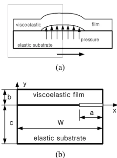
A viscoelastic thin film bonded to an elastic substrate is shown in Fig. 2(a). The osmotic pressure becomes too great for the adhesive forces holding coating film to the substrate and results in the interfacial crack of film as a solution-filled blister. Due to symmetry, only one half of the layer needs to be modeled. Fig. 2(b) represents the
SANG SOON LEE AND MYUNG KYU PARK
12 CORROSION SCIENCE AND TECHNOLOGY Vol.8, No.1, 2009
(a)
viscoelastic film
elastic substrate
a x
y b
c W
(b)
Fig. 2. Interfacial crack of film as a solution-filled blister.
two-dimensional plane strain model for analysis of the in- terfacial stresses between the film and the substrate. The osmotic pressure is assumed to be uniform along the inter- facial crack. It is further assumed that moisture effects are analogous to thermal effects. A uniform moisture change ΔmH(t) in the film is equivalent to increasing the tractions by γ(t)nj10) where
γ(t)= 3KβΔmH (t) (1)
Here, K is the bulk modulus; nj are the components of the unit outward normal to the boundary surface; and β is the coefficient of hygral expansion of the viscoelastic film.
The boundary integral equations without any other body forces are written as follows10):
For viscoelastic thin film,
) ' ( ' '
) '
;' , ) ( ' ( ) 0
;' , ( ) (
) ' ( ' '
) '
;' , ) ( ' ,' ( ) 0
;' , ( ) ,' (
) ' ( ' '
) '
;' , ) ( ' ,' ( ) 0
;' , ( ) ,' (
) , ( ) (
0 0 0
y y y y
y
y y y y
y y y
y y y y
y y y
y y
d dS n U
U n
d dS t U
U t
d dS u T
T u
u c
S
ij j m
ij j S
ij j
ij j S
ij j
ij j
j ij
∫ ⎥
⎦
⎢ ⎤
⎣
⎡ ∫ ∂
− ∂ + + +
∫ ⎥
⎦
⎢ ⎤
⎣
⎡ ∫ ∂
− ∂ +
+
=
∫ ⎥
⎦
⎢ ⎤
⎣
⎡ ∫ ∂
− ∂ +
+ +
+ + +
ξ ξ ξ
ξ ξ ξ ξ
ξ γ ξ
γ
ξ ξ ξ ξ ξ ξ
ξ ξ ξ ξ ξ ξ
ξ
(2) For elastic substrate
cij(y)uj(y,ξ)+S∫uj(y,'ξ)Tij(y,y')dS(y')
t(y,' )U (y,y')dS(y') ( )nUij(y,y')dS(y')
S j ij
S
j +∫
=∫ ξ γ ξ
(3) where uj and tj represent displacement and traction, and S is the boundary of the given domain. cij(y) is dependent
only upon the local geometry of the boundary. For y on a smooth surface, the free term cij(y) is simply a diagonal matrix 0.5δij. The viscoelastic fundamental solutions,
)
;' , (y y ξ
Uij and Tij(y,y;'ξ), can be obtained by applying the elastic-viscoelastic correspondence principle to Kelvin's fundamental solutions of linear elasticity.
In Eq. 2, ξ is the reduced time defined as follows:
ξ ξ(t) tAm
(
m(λ))
dλ0∫
=
= (4)
where Am is the shift function, a function of moisture cycle.
Under the constant moisture change ΔmH(t), the reduced time ξ of Eq. 4 becomes
ξ=Amt (5)
Eqs. 2 and 3 can be solved in a step by step fashion in time by using the modified Simpson's rule for the time integrals and employing the standard BEM for the surface integrals. Solving Eqs.2 and 3 under boundary conditions leads to determination of all boundary displacements and tractions.
The following viscoelastic model for the film is in this study
19 .
03360
. 0 1 ) 3200
(t t
E = + MPa (6)
K(t) = 3550 MPa (t : min.) (7) where E(t) is a tensile relaxation modulus, k(t) is a bulk modulus.
3. Stress intensity factor for an interfacial crack
The stress field near an interface crack between linear elastic material and linear viscoelastic material in the Laplace transformed space are given as follows6):
[ ]
⎥⎦
⎢ ⎤
⎣
⎡ ⎟
⎠
⎜ ⎞
⎝ + ⎛
=
+ =
d s r r i
iK s K
r i s
r xy
yy exp ( )ln
) 2
; , ( )
; ,
( 0 1 2 β
θ π θ τ
σ θ
(8) where
ln[ ( )]
2 ) 1
(s γ s
β = π
, κ μ μ
μ κ μ
γ
I II II
I I II
s s
s s s
+
= +
) (
) ( )
(
(9)
κI(s)=3−4sνI(s), κII=3−4νII (10)
VISCOELASTIC ANALYSIS OF OSMOTIC BLISTERING BEHAVIOR OF COATING FILM
CORROSION SCIENCE AND TECHNOLOGY Vol.8, No.1, 2009 13
0 10 20 30 40 50 60
8.70 8.71 8.72 8.73 8.74 8.75 8.76
a/b=0.03
Ko(t)/(b0.5 P)
t (min.)
0 10 20 30 40 50 60
12.60 12.61 12.62 12.63 12.64 12.65
a/b = 0.06
Ko(t)/(b0.5 P)
t (min.)
(a) (b)
0 10 20 30 40 50 60
38.38 38.39 38.40 38.41 38.42 38.43 38.44 38.45
a/b = 0.5
Ko(t)/(b0.5 P)
t (min.)
0 10 20 30 40 50 60
68.73 68.74 68.75 68.76 68.77 68.78
a/b=1.0
Ko(t) /( b0.5 P)
t (min.)
(c) (d)
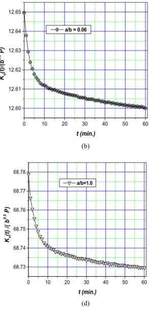
Fig. 3. Variation of overall stress intensity factors
Here and are the Laplace transformed vis- coelastic stresses, and are the Laplace trans- formed stress intensity factors, and s is the transform variable. and are Laplace transforms of the shear relaxation modulus μI(t)and the viscoelastic Poisson’s ratio νI(t).
As can be seen from Eq. 8, the stresses exhibit an oscil- lating singularity. However, the maximum amplitude of these singular stresses is determined by the overall stress intensity factor as follows:
[ ] [
2]
20 2 ( ,0; ) ( ,0; )
) lim
(t r r t r t
K yy xy
O =r π σ +τ
→ (11)
The overall stress intensity factor Ko(t) for the elas-
tic-viscoelastic interface crack can be determined from the stresses near the crack tip using Eq. 11. It is well known that by using the quarter-point element for displacement fields and the traction singular quarter-point element for the traction field, the variation of the displacements and tractions along the crack tip element is of the correct order as those established in fracture mechanics theory.8),9) The stress intensity factor can be expressed from Eq. 11 as
[ ] [ ]
2 2 21() ()
2 )
(t L t t t t
KO = π A + A
(12) where denote the BEM computed traction on the trac- tion singular crack tip element at the crack tip node and L is the length of the crack tip element.
The problem for interfacial cracks between the viscoe-
SANG SOON LEE AND MYUNG KYU PARK
14 CORROSION SCIENCE AND TECHNOLOGY Vol.8, No.1, 2009
lastic film and the elastic substrate subjected to a uniform pressure PH(t) is solved. The analysis model is shown in Fig. 2. It is assumed that (W-a)>9b. The model has 38 boundary elements for a/b = 1.0, 0.5, 0.06, 0.03. The crack tip elements are used with small crack tip element to crack length ratios (L/a) to represent properly both the
displacement behavior and 1/ traction behavior.
As a → 0 (a/b<10-3), however, the boundary element pro- cedure is inaccurate due to the instability of the crack tip elements to represent the stress singularity.
Fig. 3 shows the BEM results of Ko(t) for crack lengths a/b=1.0, 0.5, 0.06, 0.03, in which Ko(t) increases with in- creasing crack size. Ko(t) for each crack length is observed to be relaxed with time. To begin with, at time t = 0, if Ko is more than the critical value KC, the crack starts grow- ing before it reaches a stage where Ko(t) drops below that of KC and then it ceases to grow. In another situation, right at the beginning, if Ko is below the critical value KC, the crack will never grow.
4. Conclusions
The osmotic blistering behavior of polymeric coating film which is in contact with an aqueous environment has been investigated using the time-domain boundary element method . Polymeric films in general respond in a viscoe- lastic manner under loads and their time-dependent behav- ior is affected by moisture. Therefore, a time-dependent stress analysis of the film has been performed to under- stand and predict failure in coating systems. In this study, the coating film has been assumed to be linearly visco- elastic.
The overall stress intensity factor for interfacial cracks
between the viscoelastic film and the elastic substrate sub- jected to a uniform osmotic pressure has been computed using the tractions at the crack tip node. The magnitude of stress intensity factors decreases with time due to vis- coelastic relaxation, but remains constant at large times.
At time t = 0, if the overall stress intensity factor is more than the critical value, the crack starts growing before it reaches a stage where the overall stress intensity factor drops below that of the critical value and then it ceases to grow. In another situation, right at the beginning, if the overall stress intensity factor is below the critical value, the crack will never grow. The numerical procedure does not permit calculation of the limiting case for which the crack length vanishes.
References
1. D. G. Weldon, Failure Analysis of Paints and Coatings, John Wiley & Sons, Ltd., 2001.
2. P. A. Schweitzer, Paint and Coatings, CRC Press, 2006.
3. C. H. Hare, Paint Film Degradation, SSPC, 2001.
4. M. L. Williams, Bull. Seismological Society of America, 49, 199 (1959).
5. A. H. England, Journal of Applied Mechanics, 32, 400 (1965).
6. J. R. Rice, Journal of Applied Mechanics, 55, 98 (1988).
7. R. Yuuki and S. B. Cho, Engr. Fracture Mechanics, 34, 179 (1989).
8. C. L. Tan and Y. L. Gao, Engr. Fracture Mechanics, 36, 919 (1990).
9. S. T. Raveendra and P. K. Banerjee, Engr. Frac.
Mechanics, 40, 89 (1991).
10. S. S. Lee and R. A. Westmann, Int. J. Num. Methd in Engr., 38, 607 (1995).