Introduction
For early scientific studies of mummies, as they were performed in Europe starting in the 17th century,1 the wrappings of the mummies had to be removed. The ex- amination of their dentition remained limited to a visual inspection through the occasionally opened lips. This con-
sequently led to misjudgments, as in the case of Ramses II. His teeth “are clean and in an excellent state of pres- ervation: they were only slightly worn”, Smith stated in his description of the mummy unwrapped in 1886.2 A later radiographic investigation by Harris corrected this state- ment: “Ramesses II was in every sense a true dental crip- ple, suffering from extreme wear of his teeth […], extreme periodontitis […] periapical abscess”.3 The use of radiog- raphy for the non-invasive examination of mummies and their dentition then became widely used as a new meth- od of investigation.4,5 Nonetheless, Moodie, in the first systematic radiographic analysis of a major collection of mummies,6 commented that the identification of caries
Application of portable digital radiography for dental investigations of ancient Egyptian mummies during archaeological excavations: Evaluation and discussion of the advantages and limitations of different approaches and projections
Roger Seiler1, Patrick Eppenberger1,*, Frank Rühli1
1Institute of Evolutionary Medicine, University of Zurich, Zurich, Switzerland
ABSTRACT
Purpose: In the age of X-ray computed tomography(CT) and digital volume tomography(DVT), with their out- standing post-processing capabilities, indications for planar radiography for the study of the dentition of ancient Egyptian mummies may easily be overlooked. In this article, the advantages and limitations of different approaches and projections are discussed for planar oral and maxillofacial radiography using portable digital X-ray equipment during archaeological excavations. Furthermore, recommendations are provided regarding projections and sample positioning in this context.
Materials and Methods: A total of 55 specimens, including 19 skeletonized mandibles, 14 skeletonized skulls, 18 separate mummified heads, and 4 partially preserved mummies were imaged using portable digital X-ray equipment in the course of archaeological excavations led by the University of Basel in the Valley of the Kings between 2009 and 2012. Images were evaluated by 2 authors with regard to the visibility of diagnostically relevant dental structures using a 4-point grading system(Likert scale).
Results: Overall, the visibility of diagnostically relevant dental structures was rated highest by both authors on X-ray images acquired using a dental detector. The tube-shift technique in the lateral projections of mandibular dentition achieved the second-best rating, and lateral projections achieved the third-best rating.
Conclusion: Conventional planar digital X-ray imaging, due to its ubiquity, remains an excellent method-and often the only practicable one-for examining the skulls and teeth of ancient Egyptian mummies under field conditions.
Radiographic images of excellent diagnostic quality can be obtained, if an appropriate methodology regarding the selected projections and sample placement is followed.(Imaging Sci Dent 2018; 48: 167-76)
KEY WORDS: Radiography; Egypt, Ancient; Mummies; Dentition
Copyright ⓒ 2018 by Korean Academy of Oral and Maxillofacial Radiology
This is an Open Access article distributed under the terms of the Creative Commons Attribution Non-Commercial License(http://creativecommons.org/licenses/by-nc/3.0) which permits unrestricted non-commercial use, distribution, and reproduction in any medium, provided the original work is properly cited.
Imaging Science in Dentistry·pISSN 2233-7822 eISSN 2233-7830
*The first 2 authors contributed equally to this work (co-first authors).
*This study was supported by the Mäxi Foundation, Zurich, Switzerland, Commercial register number CH-020.7.001.505-8.
Received April 28, 2018; Revised July 6, 2018; Accepted July 6, 2018
*Correspondence to : Dr. Med. Patrick Eppenberger
Institute of Evolutionary Medicine, University of Zurich, Winterthurerstrasse 190, CH-8057 Zurich, Switzerland
Tel) 41-44-635-05-43, Fax) 41-44-635-01-12, E-mail) [email protected]
such purposes remained an experiment. In this setting, digital conventional X-ray systems offer significant ad- vantages. However, in any form of conventional radiog- raphy, the 3-dimensional structures of the skull base and the dentition are projected onto a 2-dimensional image.
The resulting superposition of multiple structures on ra- diographs is known as anatomical noise.12 Different types of projections can be used to avoid or at least to minimize such superposition artifacts, but they require proper posi- tioning of the head.13 When wrapped mummies are exam- ined, especially within their coffins, the orientation of the head may be inconvenient, and compensatory adjustment of the incident angle of the X-ray beam is often limited by the thickness of the coffin walls and the position of the mummy. Furthermore, positioning of the detector plate and the X-ray source can become challenging when space in storage depots is limited. In many cases, superposition of anatomical structures therefore cannot be complete- ly avoided and even the tube-shift technique remains of limited use.13 As a consequence, the interpretation of pathological changes of the dentition or the skeletal sys- tem in conventional radiographs of wrapped mummies remains challenging, and even the determination of lat- erality-that is, distinguishing between the left and right side of the dentition-is not always straightforward. CT scans allowing for later 2-dimensional multiplanar and curved multiplanar reformatting, as well as 3-dimensional volume rendering, can remedy such difficulties.14 Howev- er, for this purpose the specimens need to be transported to a facility where a CT scanner is located, at the risk of damaging fragile specimens and generating substantial costs.15 Portable digital X-ray equipment, in contrast, can be used on site and has proven its robustness under harsh conditions-heat, cold, dust, etc.-where the chemical processing of conventional X-ray film would be difficult and time-consuming.16 Furthermore, digital X-ray detec-
In this article, the advantages and limitations of differ- ent approaches and projections are discussed for planar oral and maxillofacial radiography using portable digital X-ray equipment during archaeological excavations. Fur- thermore, based on our own experiences supporting an- thropological investigations in the Valley of the Kings in Egypt, recommendations are provided regarding projec- tions and sample positioning for examining the dentition of dry skulls and mummies.
Materials and Methods
Equipment
All radiographs were acquired using portable digital planar X-ray equipment, including an X-ray generator (Examion PX 60 HF, voltage range, 40-100kV; exposure range, 0.4-100mAs; weight, 14.6 kg; Examion GmbH, Fellbach, Germany), a flat panel detector(Examion DR 1417-600 WL; scintillator, gadolinium oxysulfide; active area, 358×430mm(14inches×17inches); pixel matrix, 3072×2560 pixels; pixel pitch, 140μm; gray scale, 14 bit; weight, 3.1 kg; Examion GmbH, Fellbach, Germa- ny), a dental detector(Carestream RVG6500 DR-Sensor G2; active area, 27×36mm; pixel matrix, 1440×1920 pixels; spatial resolution, 20LP/mm; Carestream Health Inc., Rochester, NY, USA) and dedicated post-process- ing software(Examion AQS, Examion GmbH, Fellbach, Germany) running on a laptop computer(HP Elitebook 840 G3, LT4120 Snapdragon X5 LTE; HP Inc., Palo Alto, CA, USA) with Microsoft Windows 7 Enterprise Edition (Microsoft Corporation, Redmond, WA, USA) as the op- erating system.
Samples
The dentition of ancient Egyptian skulls and mum- mies was examined under field conditions, supporting
the anthropological analysis of these human remains during excavations led by the University of Basel in the Valley of the Kings. The Valley of the Kings Project of the University of Basel started in 2009. Subsequently, in 2010, research in tomb KV 31 was initiated, where the remains of 4 mummies, assigned to the mid-18th dynas- ty, were found. In the same year work began in tomb KV 40, where the first anthropological field season started in 2014, with ongoing research to this day. So far, the human remains of more than 80 individuals dating from the 18th dynasty and from the tombs’ reuse during the 22nd dynas- ty have been found, however most are severely damaged and scattered by looting and fire. Tomb KV 64 was dis- covered in 2012, containing the mummy of the original tomb owner from the 18th dynasty, as well as the mummy of Nehemesbastet from the 22nd dynasty. The specimens included in this study ranged from fully skeletonized, iso- lated dry skulls to isolated mummy heads with preserved soft tissue, as well as entire mummies with or without preserved wrappings. A total of 55 specimens, includ- ing 19 skeletonized mandibles, 14 skeletonized skulls, 18 separate mummified heads, and 4 partially preserved mummies, were subjected to radiographic assessment(in addition to photographic documentation). A frequent in-
dication for X-ray imaging was age determination in chil- dren. Many of the excavated specimens, however, such as isolated mandibular fragments, did not need radiological assessment and were not included in this study.
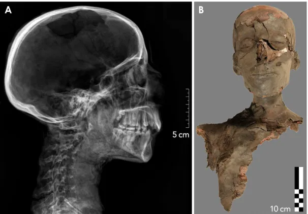
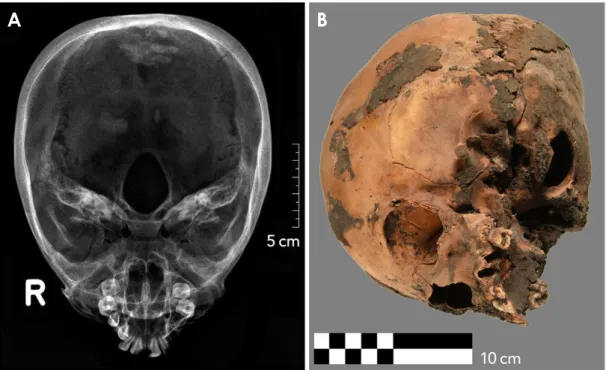
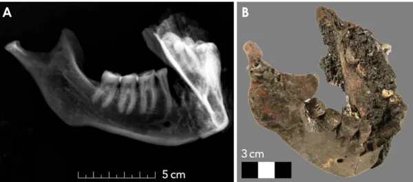
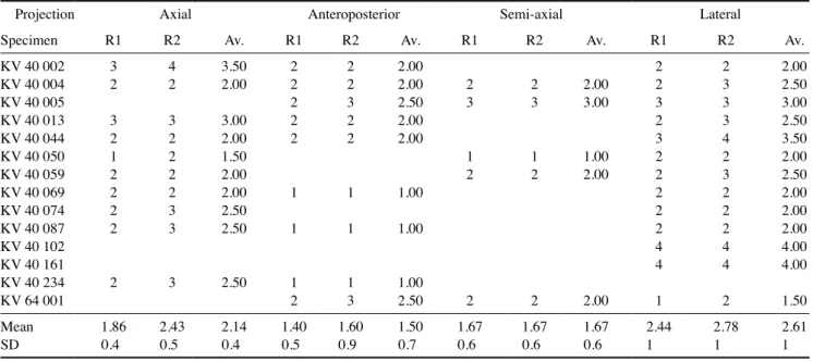
Specimens were divided into the following 4 catego- ries, according to the practicability of various radiograph- ic projections: 1) Partial or complete mummies(4 speci- mens): The facial skull(upper and lower jaw), including the soft tissues as well as the cranium and the shoulder belt, were at least partly preserved, with consequent lim- itations for positioning of the detector plate(Fig. 1). 2) Mummified heads(18 specimens): The entire facial skull (upper and lower jaw) including perioral soft tissues was preserved, and possibly also the cranium, with or without soft tissues(Fig. 2). 3) Skeletonized upper jaws(14 spec- imens): At least the facial skull was preserved, without any perioral soft tissues, including whole skulls(Fig. 3). 4) Skeletonized mandibles(19 specimens): An isolated man- dible was preserved(Fig. 4). Frequently, only one-half of the mandible was found, and such half-mandibles could then easily be imaged using a lateral projection.
Projections
All projections, as used for planar oral and maxillofa-
A B
Fig. 1. Example of a partial mummy excavated in tomb KV 40, specimen number KV 40 080. A. Conventional digital radiograph, where the lateral projection provides an excellent overview. B. Correlative photograph, frontal view.
cial radiography with portable digital X-ray equipment during the aforementioned excavations, are listed and ex- plained below. The source-image distance was always set
to approximately 120cm. The properties and indications of specific projections are explained below.
1. For the lateral/cephalometric skull projection, here-
Fig. 2. Example of a mummified head in tomb KV 40, specimen number KV 40 038. A. Conventional digital radiograph, lateral projection.
B. Photograph in the frontal view of the same specimen.
A B
Fig. 3. Example of a specimen classified as a skeletonized upper jaw(whole skull) excavated in tomb KV 40, specimen number KV 40 002. A. Conventional digital radiograph, axial(cranio-caudal) projection. B. Correlative photograph, angled view.
after referred to as the “lateral” projection, the detector plate is placed parallel to the central sagittal plane of the skull, with the central ray’s incidence perpendicular to the detector plate, centered about 1 cm above the outer audi- tory canal. The sella turcica should be projected as a sin- gle line. For a tube-shift projection, a second image can be taken with the radiation source displaced in the axial direction.
2. The anteroposterior skull projection provides a good overview of the entire skull. Here the back of the skull is placed against the detector plate, with the central ray’s incidence perpendicular to the detector plate and centered on the nasion. The image should be symmetrical and free of any rotation, with both orbital edges looking similar.
The petrous ridge should overlap the lower third of the orbits.
3. The axial submentovertex skull projection, hereaf- ter referred to as the “axial” projection, shows the inner temporal bone structures and the skull base in addition to the dentition. For this projection, the vertex of the skull is placed against the detector plate. The infraorbitomeatal line is aligned parallel to the detector plate, with the cen- tral ray’s incidence perpendicular to the detector plate, centered approximately 4 cm inferior to the mandibular symphysis.
4. For the semi-axial anteroposterior skull projection, hereafter referred to as “semi-axial” projection, the back of the skull is placed against the detector plate with per- pendicular alignment of the mento-mandibular line. The central ray’s incidence is also perpendicular to the detec- tor plate, centered on the acanthion. In this projection, the
petrous ridges should project below the maxillary sinuses.
Assessment of coronoid process symmetry will ensure ro- tation-free alignment.
5. The lateral-oblique mandibular projection is obtained through parallel alignment of the lateral external surface of the mandible and the detector plate. To avoid superim- position of the opposite side of the jaw, the angle of inci- dence of the central ray should remain perpendicular to the detector plate, centered 2cm below and 2cm behind the mandibular angle of the contralateral side(i.e., the side of the X-ray tube).
6. The axial mandibular projection is an axial cranio- caudal projection of an isolated mandible. For this pro- jection, the mandible is placed with its inferior borders aligned parallel to the detector plate. The central ray’s incidence is perpendicular to the detector plate, centered between both mandibular condyles.
7. “Intraoral” radiography is taken using a dental de- tector in the parallel periapical projection or in the bisect- ing-angle periapical projection. Due to its superior spatial resolution, it can provide valuable additional information and is applicable in skeletonized upper and lower jaws.
Evaluation and statistical analysis
All images were evaluated by 2 of the authors with different levels of experience in dental radiography (a board-certified dentist with 30 years of experience (R1=R.S.) and a fifth-year medical resident with exten- sive radiological and paleoradiological experience(R2=P.
E.) with regard to the visibility of diagnostically relevant dental structures using a 4-point grading system(Likert
A B
Fig. 4. Example of a mandible excavated in tomb KV 40, specimen number 657. A. Conventional digital radiograph, where the later- al-oblique projection provides an optimal representation of the right tooth row. B. Correlative photograph.
scale): 1, poor visibility(no details, mainly due to super- position, were recognizable); 2, moderate visibility(details of the tooth rows were only partially discernible, or only a part of a tooth row was distinguishable); 3, good visibility (details of the tooth rows and the periodontal tissue were well identifiable); 4, excellent visibility(details of teeth, interdental septa, the periapical region, etc., were clearly visible). Statistical analysis was performed by one of the authors(P.E.) using dedicated software(IBM SPSS Statis- tics, release 24, IBM Corp., Armonk, NY, USA). Interob- server agreement was assessed by calculating intraclass correlation coefficients(ICCs)18,19 based on a mean rating (k=2), a 2-way mixed-effects model, and the “absolute agreement” definition. The following interpretation for
the ICCs was used: values less than 0.5 were considered to indicate poor reliability, values between 0.5 and 0.75 indicated moderate reliability, values between 0.75 and 0.9 indicated good reliability, and values greater than 0.90 indicated excellent reliability.
Results
Images could be acquired successfully within the ex- pected practical limitations according to our experiences from previous similar expeditions.
Skeletonized skulls comprising the dentition of the up- per jaw were mainly radiographed using the lateral, an- teroposterior or semi-axial projections, primarily for eval- Projection Axial Anteroposterior Semi-axial Lateral-oblique Tube-shift Lateral
Specimen R1 R2 Av. R1 R2 Av. R1 R2 Av. R1 R2 Av. R1 R2 Av. R1 R2 Av.
KV 40 001 3 3 3.0 3 3 3.0 3 3 3.0 3 4 3.5
KV 40 010 2 2 2.0 1 1 1.0 3 3 3.0 3 4 3.5
KV 40 011 2 2 2.0 2 2 2.0 2 3 2.5
KV 40 021 2 3 2.5 2 2 2.0 3 3 3.0 3 3 3.0
KV 40 024 2 2 2.0 1 1 1.0 1 1 1.0 4 4 4.0 4 4 4.0 3 3 3.0
KV 40 025 1 1 1.0 2 3 2.5 2 2 2.0 3 4 3.5
KV 40 026 2 3 2.5 1 2 1.5 2 2 2.0 3 3 3.0 3 3 3.0
KV 40 027 1 2 1.5 2 2 2.0 3 3 3.0 3 4 3.5
KV 40 038 2 3 2.5 2 2 2.0 3 3 3.0 3 3 3.0
KV 40 046 1 2 1.5 3 4 3.5
KV 40 047 2 2 2.0 3 3 3.0
KV 40 051 2 2 2.0 2 2 2.0 2 2 2.0 3 3 3.0 3 3 3.0
KV 40 052 1 1 1.0 2 2 2.0 2 2 2.0
KV 40 053 2 3 2.5 2 2 2.0 3 3 3.0 3 3 3.0
KV 40 060 2 3 2.5 2 3 2.5 3 3 3.0 2 2 2.0
KV 40 067 3 4 3.5 1 1 1.0 2 2 2.0
KV 40 173 1 1 1.0 2 2 2.0 2 3 2.5
KV 31 002 2 2 2.0 2 2 2.0 2 2 2.0 2 3 2.5
Mean 1.9 2.3 2.1 1.7 2.1 1.9 2.0 2.0 2.0 4.0 4.0 4.0 3.0 3.0 3.0 2.7 3.1 2.9
SD 0.6 1 0.8 0.6 0.8 0.7 0.4 0.4 0.4 0.4 0.4 0.4 0.5 0.7 0.5
SD: standard deviation, R: reader, Av.: average
uation of the osseous structures. However, the dentition was only partially assessable with these projections. Later- al projections provided good results in all categories.
The lateral-oblique projection was only applicable for mandibles, while axial projections could be applied for
both isolated skulls and mandibles. In addition, the skele- tonized upper and lower jaws were accessible for the small, high-resolution dental detector. This procedure was, however, not applicable when perioral soft tissues were preserved, leaving the oral cavity inaccessible. Isolated
Table 3. Reader ratings for skeletonized upper jaws, including entire skulls
Projection Axial Anteroposterior Semi-axial Lateral
Specimen R1 R2 Av. R1 R2 Av. R1 R2 Av. R1 R2 Av.
KV 40 002 3 4 3.50 2 2 2.00 2 2 2.00
KV 40 004 2 2 2.00 2 2 2.00 2 2 2.00 2 3 2.50
KV 40 005 2 3 2.50 3 3 3.00 3 3 3.00
KV 40 013 3 3 3.00 2 2 2.00 2 3 2.50
KV 40 044 2 2 2.00 2 2 2.00 3 4 3.50
KV 40 050 1 2 1.50 1 1 1.00 2 2 2.00
KV 40 059 2 2 2.00 2 2 2.00 2 3 2.50
KV 40 069 2 2 2.00 1 1 1.00 2 2 2.00
KV 40 074 2 3 2.50 2 2 2.00
KV 40 087 2 3 2.50 1 1 1.00 2 2 2.00
KV 40 102 4 4 4.00
KV 40 161 4 4 4.00
KV 40 234 2 3 2.50 1 1 1.00
KV 64 001 2 3 2.50 2 2 2.00 1 2 1.50
Mean 1.86 2.43 2.14 1.40 1.60 1.50 1.67 1.67 1.67 2.44 2.78 2.61
SD 0.4 0.5 0.4 0.5 0.9 0.7 0.6 0.6 0.6 1 1 1
SD: standard deviation, R: reader, Av.: average
Table 4. Reader ratings for skeletonized mandibles
Projection Dental detector Axial Anteroposterior Lateral-oblique Lateral
Specimen R1 R2 Av. R1 R2 Av. R1 R2 Av. R1 R2 Av. R1 R2 Av.
KV 40 004 3 4 3.5
KV 40 039 1 2 1.5 3 4 3.5
KV 40 050 2 2 2.0 2 2 2.0
KV 40 090 4 4 4.0
KV 40 092 3 4 3.5
KV 40 162 4 4 4.0
KV 40 234 3 3 3.0
KV 40 248 2 3 2.5 3 3 3.0
KV 40 322 2 2 2.0 3 3 3.0
KV 40 607 4 4 4.0 2 3 2.5 3 3 3.0
KV 40 608 2 2 2.0 2 2 2.0
KV 40 609 4 4 4.0
KV 40 610 4 4 4.0 3 4 3.5
KV 40 656 2 3 2.5 3 4 3.5
KV 40 657 2 2 2.0 3 4 3.5
KV 40 685 3 4 3.5
KV 40 689 3 3 3.0
KV 40 690 3 3 3.0
KV 64 001 2 3 2.5
Mean 4.0 4.0 4.0 2.0 2.6 2.3 2.0 2.0 2.0 2.8 3.4 3.1 3.1 3.5 3.3
SD 0 0 0 0.5 0.7 0.5 0.4 0.5 0.4 0.5 0.7 0.6
SD: standard deviation, R: reader, Av.: average
Descriptive statistical data(semi-quantitative data) for both readers(R1 and R2), as well as the mean values of both readers are listed in Tables 1-4. ICC calculations showed that the 2 readers had good consistency in their ratings of diagnostic image quality, with values of 0.765 for single measures and 0.867 for average measures.
Overall, the visibility of diagnostically relevant dental structures was rated highest by both authors on X-ray im- ages acquired using the dental detector(consistent ratings of 4 points on the 4-point Likert scale for the imaged mandibles), the high resolution of which revealed the fin- est dental and osseous structures, but at the cost of a very small detector size(27×36mm). Tube-shift projections of the dentition used for the imaging of mummified heads and entire or partial mummies achieved the second-best rating(average over both readers of 3.0±0.4 points on the 4-point Likert scale), with well-identifiable details of tooth rows and periodontal tissues, but with a slight- ly lower resolution, since a standard-size digital detector was used(358×430mm). Lateral projections achieved the third-best ratings(average ratings of 2.5±0.4, 2.89±
0.5, 2.61±1, and 3.27±0.6 on the 4-point Likert scale) for entire or partial mummies, mummified heads, skele- tonized upper jaws, and skeletonized mandibles, respec- tively, still providing images of acceptable diagnostic quality. Lateral projections were the most used type of projection(in 46 out of 55 specimens).
Discussion
This article reflects radiographic fieldwork over a rela- tively long period of time. According to our experiences, we can give some recommendations to facilitate a practi- cable workflow in similar conditions:
1. Fully skeletonized skulls can be positioned in almost any desired projection. Therefore, even “intraoral” shots
Axial radiographs, using a larger standard-size X-ray de- tector, give an overview of the whole dentition, possibly impacted teeth, or the cortices of the upper and lower jaw.
An anteriorly or laterally shifted axial projection can pro- vide additional information on the frontal or lateral part of the dentition. In such cases, the skull or the mandible can directly be placed on the detector. In addition, the “extra- oral,” lateral-oblique projection of the mandible, again using the larger standard-size X-ray detector, provides a good overview of the posterior teeth and the adjacent osseous structures. Therefore, in case of dry skulls, the specified “intraoral” techniques using the dental detector can be combined with an “extraoral” technique using a larger standard-size X-ray detector.
2. Isolated mummy heads with preserved soft tissue, in contrast, may still be freely positioned, but the intraoral space is no longer accessible due to the completely dried and rigid soft tissues. Therefore, lateral, axial, anteropos- terior, semi-axial, and lateral-oblique projections have to be performed. The anteroposterior projection should be favored over the usual posteroanterior projection. This way, the fragile soft tissue structures of the face, includ- ing the nose, the lips, the chin, and the skin covering the supraorbital region, are at less risk of being damaged, since the head rests on its occipital region. The distortion resulting from the greater distance to the detector plate seems to be an acceptable trade-off in order to prevent damaging the specimen. Such a set of projections pro- vides a good overview of the skull, the skull base, and the oral and maxillofacial structures. In semi-axial projec- tions, defects of the skull base, often created for excere- bration, can be identified and localized in the ethmoid or sphenoid region.20 The superposition of the right and the left tooth row can present a further problem, which can be countered by the tube-shift technique. This technique helps to reduce superposition and allows the laterality of
the rows of the dentition to be determined. For this, two additional images, one with a more cranial and one with a more caudal positioning of the X-ray tube, are required.
The row of teeth nearer to the detector plate will then move “with” the tube, and in this manner, the right and left sides can be distinguished.
3. In cases of an entire mummy, with its head still at- tached to the rest of the body, the situation is again differ- ent. Most the time the head’s position is set and can only be slightly moved or may even not be altered at all. Nev- ertheless, under such conditions the intended projection of an X-ray image should still be directly verified. If the wrappings of a mummy are still preserved or if the mum- my rests in a coffin or a cartonnage, a test shot is recom- mended to obtain information about the posture and the localization of the head. The positioning of the X-ray tube and the detector plate can then be adjusted for further im- ages of the desired projections.
We would also like to mention some of the limitations of our study. Since some of the discussed projections are only applicable for certain types of specimens, the num- ber of evaluated projections per object was small, which has to be considered in addition to the inherent limitations of semi-quantitative grading systems. In addition, the number and type of radiographs acquired mainly depend- ed on the anthropologists’ questions. The main objective therefore was not the production of “clinically correct”
images, but to answer questions such as determination of the age at death, which explains some of the qualitative limitations of the resulting X-ray images.
In conclusion, radiographic examination of the denti- tion and its adjacent structures in the context of archeo- logical excavations is a challenging task. New imaging modalities, such as CT and DVT, have substantially im- proved diagnostic capabilities in routine clinical prac- tice.21 With some limitations, this also applies to mum- my research. However, when investigations have to take place under field conditions, conventional planar digital X-ray imaging, due to its ubiquity, remains an excellent method-and often the only practicable one-for exam- ining the skulls and teeth of ancient Egyptian mummies.
Despite challenging field conditions, radiographic images of excellent diagnostic quality can be obtained, if an ap- propriate methodology regarding the selected projections and sample placement is followed.
Acknowledgements
We thank the Mäxi Foundation for supporting this study
(Mäxi Foundation, Zurich, Switzerland, Commercial reg- ister number CH-020.7.001.505-8).
We thank Professor Susanne Bickel for supporting our radiological research during the excavations in the Val- ley of the Kings in Egypt(Prof. Dr. Susanne Bickel, De- partment of Antiquities of the University of Basel, Basel, Switzerland).
References
1. Gryphius A. And. Gryphii mumiae wratislavienses. Wrocław:
Sumptibus Viti Jacobi Drescheri; 1662.
2. Smith GE. The royal mummies. London: Bristol Classical Press; 2000.
3. Harris JE, Wente EF. An X-ray atlas of the royal mummies.
Chicago: University of Chicago Press; 1980.
4. Cosmacini P, Piacentini P. Notes on the history of the radio- logical study of Egyptian mummies: from X-rays to new im- aging techniques. Radiol Med 2008; 113: 615-26.
5. Böni T, Rühli FJ, Chhem RK. History of paleoradiology: early published literature, 1896-1921. Can Assoc Radiol J 2004; 55:
203-10.
6. Lynnerup N. Mummies. Am J Phys Anthropol 2007; Suppl 45: 162-90.
7. Moodie RL. Roentgenologic studies of Egyptian and Peruvian mummies. Chicago: Field Museum of Natural History; 1931.
8. Gerald C. Considered limitations and possible applications of computed tomography in mummy research. Anat Rec(Hobo- ken) 2015; 298: 1088-98.
9. Scheinfeld MH, Shifteh K, Avery LL, Dym H, Dym RJ.
Teeth: what radiologists should know. Radiographics 2012;
32: 1927-44.
10. Youssefzadeh S, Gahleitner A, Bernhart D, Bernhart T. Con- ventional dental radiography and future prospectives. Radiol- oge 1999; 39: 1018-26.
11. Conlogue G, Nelson A. Polaroid imaging at an archaeological site in Peru. Radiol Technol 1999; 70: 244-50.
12. Olsson L, Nilsson M, Svenson B, Hellén-Halme K. The effect of anatomical noise on perception of low contrast in intra-oral radiographs: an in vitro study. Dentomaxillofac Radiol 2016;
45: 20150402.
13. Rühli FJ, Chhem RK, Böni T. Diagnostic paleoradiology of mummified tissue: interpretation and pitfalls. Can Assoc Ra- diol J 2004; 55: 218-27.
14. Abrahams JJ. Dental CT imaging: a look at the jaw. Radiology 2001; 219: 334-45.
15. Cox SL. A critical look at mummy CT scanning. Anat Rec (Hoboken) 2015; 298: 1099-110.
16. Rühli F, Ikram S, Bickel S. New ancient Egyptian human mummies from the Valley of the Kings, Luxor: anthropolog- ical, radiological, and Egyptological investigations. Biomed Res Int 2015; 2015: 530362.
17. Teich S, Al-Rawi W, Heima M, Faddoul FF, Goldzweig G, Gutmacher Z, et al. Image quality evaluation of eight com- plementary metal-oxide semiconductor intraoral digital X-ray sensors. Int Dent J 2016; 66: 264-71.