Vol.18, No.4, (2016), pp.30~34 http://dx.doi.org/10.9714/psac.2016.18.4.030
```
1. INTRODUCTION
The high-voltage direct-current (HVDC) system is used worldwide for long-distance, large-volume electric power transmission. The breaking capacity and time of the DC circuit breaker, which is the protection equipment for the grid, is an important element in improving the stability and reliability of the HVDC system. The DC current has no zero current point, and a high arc voltage appears across the DC circuit breaker when it conducts breaking operation [1-4]. If a high arc voltage damages the insulation or if the burden on the circuit breaker exceeds the breaker’s circuit breaking capacity, it can lead to a blackout, or in the worst-case scenario, to the collapse of the entire grid.
In this study, the SFCL-combined DC circuit breaker system was proposed to improve the DC circuit breaker performance, by applying the superconductor current-limiting technology to the conventional DC circuit breaker system using the EMTDC/PSCAD [5]. A mechanical DC circuit breaker system was used in this study.
2. PREVIOUSLY PROPOSED DC BREAKER SYSTEM
2.1. Design and conditions
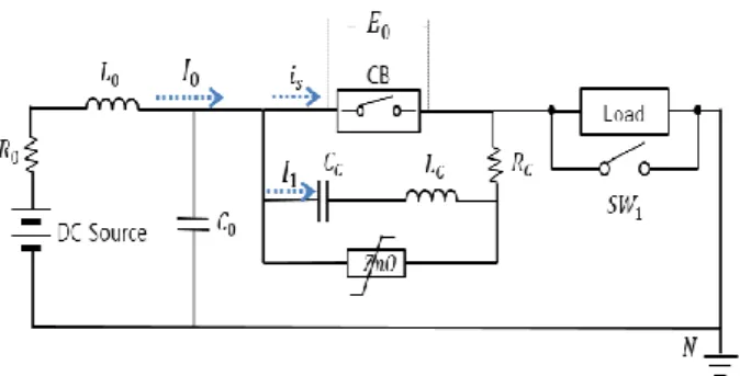
The mechanical DC circuit breaker has a circuit-breaking circuit, an oscillation circuit, and a surge circuit. The circuit-breaking circuit has mechanical contacts, and the oscillation circuit has an LC circuit with the inductance (L) and the capacitor (C) connected in series.
Finally, the surge circuit has a lightning arrester.
Fig. 1 shows the circuit of the previously proposed DC
Fig.1. Conventional DC Circuit Breaker system.
circuit breaker modeled using the EMTDC/PSCAD program. R
o, L
o, and C
oare line constants, and the values were set at R
o=1 Ω, L
o=100 mH and C
o=1 μF. A mechanical DC circuit breaker was used, along with a gapless ZnO lightning arrester, which had an excellent discharge characteristic, a low limit voltage, and a simple structure. The constants for the oscillation circuit were set at Rc=1 Ω Lc=1 mH and Cc=100 μF. The load was set at 100 Ω, and SW1 represents the fault generation switch.
The DC sources that were applied to the grid were 150, 250, and 450 kV. These voltages corresponded to the grid voltages of the actual HVDC grids: Gotland HVDC link (Sweden), Jindo-Jeju link (South Korea), and HVDC transmission Quebec-New England (North America) [6-7].
The fault occurs 2 seconds after the beginning of the simulation, and the fault duration was 0.5 sec. As the circuit breaker had mechanical contacts to operate and therefore the opening operation would occur at 2.01 sec (2010 ms).
2.2. Simulation results
Fig. 2 shows the voltage and current characteristics of the DC circuit breaker system when the applied voltage was 150 kV. When the DC voltage source supplied the voltage
Interruption analysis of the SFCL-combined DC circuit breaker system using current-limiting technology
Jun-Beom Kim
*, In-Sung Jeong, Hye-Won Choi, and Hyo-Sang Choi Chosun University, Gwangju, Korea
(Received 31 October 2016; revised or reviewed 25 December 2016; accepted 26 December 2016)
Abstract
In this study, a SFCL-combined DC circuit breaker system was proposed by applying the current-limiting technology for DC circuit breaking. The SFCL-combined circuit breaker system consists of a mechanical DC circuit breaker combined with superconductors. To ensure the reliable structure and operation of the SFCL-combined circuit breaker system, a simulation grid was designed using the EMTDC/PSCAD program, and simulation was conducted. The results showed that the SFCL-combined DC circuit breaker system with superconductors limited the maximum fault current by 37%. In addition, the burden on the DC circuit breaker was decreased by 87%.
Keywords : Direct Current(DC), Direct Current Circuit Breaker(DCCB), High Voltage Direct Current(HVDC), SFCL DCCB, Superconductivity
* Corresponding author: [email protected]
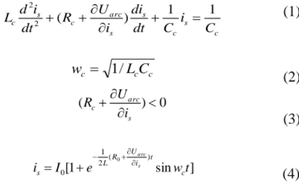
of 150 kV to the circuit, the steady state current of 2.94 kA was conducted for 2 sec (2000 ms). When the fault generation switch (SW1) generated a 2 sec (2000 ms) simulated fault, however, an 16.81 kA fault current appeared, and a 258.47 kV voltage appeared across the circuit breaker. At 2.01 sec (2010 ms), the circuit breaker conducted the opening operation. As soon as the circuit breaker opened the circuit, the oscillation current flowed into the breaking circuit, and an artificial zero appeared according to (1-4) where U
arcmeans the arc voltage across the circuit breaker in the breaking circuit and w
cmeans the frequency of the oscillation circuit.
c s c s s arc c s
c
i C
C dt di i R U dt
i
L d 1 1
)
2
(
2
(1)
w
c 1 / L
cC
c(2)
0 )
(
s arc
c
i
R U
(3) [ 1 sin ]
) 2 (
1 0
0
t w e
I
i
ci t R U L s
s a rc
(4)
Accordingly, the voltage and current across the circuit breaker decreased [3]. In addition, the lightning arrester in the surge circuit transmitted the residual voltage of the circuit breaker and oscillation circuit.
Fig. 3 shows the voltage and current characteristics of the DC circuit breaker system when the applied voltage was 250 kV DC. When the power was applied, a 4.9 kA steady-state current flowed into the circuit. Through the simulated fault at 2 sec, a 28.76 kA fault current was generated, and a 477.40 kV voltage appeared across the circuit breaker. As mentioned earlier, the oscillation current flowed into the breaker circuit and created the zero current point according to (1-4). This reduced the magnitude of the voltage and current in the breaker circuit, and the residual voltage was discharged through the lightning arrester.
Fig. 4 shows the voltage and current curves of the DC circuit breaker system when the applied voltage was 450 kV. For 2 sec, an 8.82 kA steady-state current flowed into the line. When a fault was simulated by SW1, however, a 51.73 kA fault current was generated. A 957.47 kV voltage appeared across the circuit breaker in the breaker circuit.
Then the operations conducted in the 150 and 250 kV cases were repeated.
In the three cases simulated above (150, 250, and 450 kV), continuous attenuation vibration occurred during the fault cycle (500 ms). If the fault cycle were longer than 500 ms, the attenuation vibration would have continued.
Therefore, it seems that the breaking operation was not completed in the DC circuit breaker system.
3. SFCL-combined DC CIRCUIT BREAKER SYSTEM
The simulation results of the previously proposed DC circuit breaker system showed that there was no complete breaking operation. Therefore, additional auxiliary devices seem to be needed for the DC circuit breaker system.
Fig.2. Voltage and current curves of the DC circuit breaker system at 150 kV.
Fig.3. Voltage and current curves of the DC circuit breaker system at 250 kV.
Fig.4. Voltage and current curves of the DC circuit breaker system at 450 kV.
Fig.5. SFCL-combined DC Circuit Breaker System.
Fig.6. Quench Characteristic of the Designed Superconductor.
3.1. Novel design and conditions
The SFCL-combined DC circuit breaker system is based on the DC current-limiting technique recently proposed by the authors, which combines the conventional DC circuit breaker system with the superconductor. Fig. 5 shows the circuit diagram of the SFCL-combined DC circuit breaker system. The superconductors are arranged in series ahead of the mechanical DC circuit breaker. The superconductor limits the maximum fault current before the circuit breaker starts the opening operation [8]. The mechanical circuit breaker conducts the breaking operation when the fault current that has first been limited flows in. The other circuit parameters are all same as Fig.1 except for the superconducting elements.
3.2. Superconductor design
In this study, the current-limiting technology with the superconductor was employed. The superconductor operates without impedance in the normal condition. Thus, it does not generate any loss in the line, and does not give the burden on the line when the load current is applied. Upon the occurrence of a fault, however, it detects the fault, and quenching for a few milliseconds generates a specific high impedance to limit the fault current. Fig. 5 shows the SFCL-combined DC circuit breaker system. Fig. 6 shows the quench characteristic for the superconductor designed based on (5) where R
mmeans maximum quenching resistance and T
scmeans time constant for quenching characteristic [9].
(T
sc=0.75 ms; R
m=20 Ω; quench time=6 ms).
) (
)) / exp(
1 (
) (
) 0
( R t T t t
t t t
R
quenching SC
m
quenching SFCL
( 5)
3.3. Simulation results
Fig. 7 shows the voltage and current characteristics when 150 kV was applied to the SFCL-combined DC circuit breaker system. In the normal condition, a 2.94 kA steady-state current flows into the circuit. When a fault was generated at 2 sec (2000 ms), the superconductor was quenched after the quench time set 6 ms, and limited the maximum fault current to 9.8 kA. A 253.42 kV voltage appeared across the circuit breaker. The current limited by the superconductor flowed into the mechanical circuit breaker, and the circuit breaker opened the circuit after 4 ms at 2.01 sec. At the same time, as mentioned above, a zero current point was created in the circuit according to (1-4), and the breaking operation was completed in 33 ms.
Fig.7. Voltage and current curves of the SFCL-combined DC circuit breaker system at 150 kV.
Fig.8. Voltage and current curves of the SFCL-combined DC circuit breaker system at 250 kV.
Fig.9. Voltage and current curves of the SFCL-combined DC circuit breaker system at 450 kV.
Fig. 8 shows the voltage and current characteristics of the SFCL-combined DC circuit breaker system when the applied voltage was 250 kV. When 250 kV was applied, a 4.9 kA steady-state current stably flowed into the circuit for 2 sec. When SW1 generated a simulated fault, the superconductor was quenched at 2.006 sec (2006 ms) and generated impedance to first limit the fault current to 18.83 kA. The voltage that was applied to the breaker circuit was 430.18 kV. Then the operations that had been conducted in the 150 kV cases were repeated. A fault occurred, but it was interrupted in 39 ms.
Fig. 9 shows the operation characteristics of the
SFCL-combined DC circuit breaker system when the applied
voltage was 450 kV DC. An 8.82 kA steady-state current
also flowed into the line. As soon as a fault was simulated,
however, the superconductor was quenched, and the
maximum fault current was first limited to 34.16 kA. An
825.80 kV voltage appeared across the circuit breaker. The fault current first limited by the superconductor flowed into the circuit breaker, and the circuit breaker opened the circuit at 2.01 sec after 2010 ms. In addition, a zero current point was created in the circuit according to (1-4), and the breaking operation was completed in 42 ms.
4. CONSIDERATION
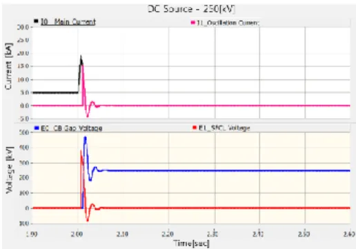
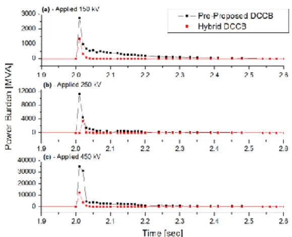
Fig. 10 shows the burden on the DC circuit breaker with and without the superconductor.
Fig. 10(a) shows the burden on the DC circuit breaker when the applied voltage was 150 kV. The power burden for the conventional DC circuit breaker system without the superconductor had a 129.83 MVA power burden. The SFCL-combined DC circuit breaker system with the superconductor had a 17.62 MVA power burden, which was 7.3 times lower. (6) offers the burden applied to the DC circuit breaker. Where t
omeans initiating time, E
smeans gap voltage and I
smeans interrupting current.
0
_
t s s