Evaluating the Effectiveness of Quasi-Zenith Satellite System on Positioning Accuracy Based on 3D Digital Map Through Simulation
Yong-Cheol Suh, Yusuke Konishi, Ryosuke Shibasaki Center for Spatial Information Science,
Institute of Industrial Science, University of Tokyo 4-6-1 Komaba, Meguro-ku, Tokyo 153-8505, JAPAN Tel & Fax: (81)-3-5452-6417, E-mail: [email protected]
ABSTRACT
Since the operation of the first satellite-based navigation services, satellite positioning has played an increasing role in both surveying and navigation, and has become an indispensable tool for precise relative positioning. However, in some situations, e.g. at a low angle of elevation, the use of satellites for navigation is seriously restricted because obstacles like buildings and mountains can block signals. As a mean to resolve this problem, the quasi-zenith satellite system has been proposed as a next-generation satellite navigation system.
Quasi-zenith satellite is a system which simultaneously deploys several satellites in a quasi-zenith geostationary orbit so that one of the satellites always stay close to the zenith if viewed from a specific point on the ground of East Asia. Thus, if a position measurement function compatible with GPS is installed in the quasi-zenith and stationary satellites, and these satellites are utilized together with the GPS, four satellites can be accessed simultaneously nearly all day long and a substantial improvement in position measurement, especially in metropolitan areas, can be achieved.
The purpose of this paper is to evaluate the effectiveness of quasi-zenith satellite system on positioning accuracy improvement through simulation by using precise orbital information of the satellites and a three-Dimensional digital map. Through this simulation system, it is possible to calculate the number of simultaneously visible satellites and available area of the positioning without the need of actual observation.
Keywords: Quasi-zenith satellite, Orbital information, Positioning accuracy, 3D digital map, Simulation
1. INTRODUCTION
In recent years, satellite-based navigation has been widely used in positioning. On the other hand, the demand for higher accuracy and wider applicability has been continuously increasing. It is well known that the accuracy, availability and reliability of the positioning results are heavily dependent on the number and geometric distribution of tracked satellites. However, in some situations, e.g. at a low angle of elevation, the number of visible satellites may not be sufficient to reliably determine precise coordinates. As a mean to resolve this problem, the quasi-zenith satellite system has been proposed.
Quasi-zenith satellite is a system which simultaneously
deploys several satellites in a quasi-zenith geostationary
orbit so that one of the satellites always stay close to the
zenith if viewed from a specific point on the ground of
East Asia. The satellites are placed into three different
orbits separated by 120 degrees and always have an
angle of elevation to East Asia of 70 degrees or more,
thus enabling synchronization of the ground locus. Since
in addition to having features equivalent to those of
conventional satellites, the orbit of the quasi-zenith
satellite is such that it remains nearly stationary above
East Asia region. Thus, quasi-zenith satellite system
provides highly accurate measurements for positioning
services. Therefore, if a position measurement function
compatible with GPS is installed in the quasi-zenith and
stationary satellites, and these satellites are utilized together with the GPS, four satellites can be accessed simultaneously nearly all day long and a substantial improvement in position measurement especially in metropolitan areas can be achieved. Accordingly, it is anticipated that the quasi-zenith satellite system will contribute to more accurate and reliable positioning services by providing users better line-of-sights to the satellites. However, to adopt this quasi-zenith satellite system as a national undertaking on a larger scale, it is necessary to evaluate how this system may complement the existing satellite-based positioning and improve the positioning accuracy. The purpose of this paper is to evaluate the effectiveness of the quasi-zenith satellite system on positioning accuracy using precise orbital information of the satellite and a three- dimensional digital map through simulation.
2. CHARACTERISTICS OF QUASI-ZENITH SATELLITE SYSTEM
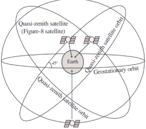
The quasi-zenith satellite system is a satellite constellation consisting of three or more satellites placed in inclined geo-synchronous circular orbits with an inclination of around 45 degrees. The satellite is also called the figure-8 satellite because the locus of the sub-satellite point of this satellite traces a figure “8” from the north to the south centering a place at the equator.
The quasi-zenith satellite system has not been formally defined yet, but it is a satellite constellation with at least three satellites. The satellites work in three shifts of eight hours; at least one of three satellites can be seen near the zenith.
Arrangement of Quasi-Zenith Satellite Orbits
The quasi-zenith satellite is, to be precise, a satellite that has an inclined geo-synchronous orbit. This orbit has the same orbital altitude (35,786km) as a geostationary orbit and has an inclination such as that shown in Figure 1. The satellite revolves once a day synchronously as the earth rotates. When the quasi-zenith satellite system is
used for East Asia, three satellite are located on the figure “8”. The three satellites are not orbiting the same inclined orbit, but are deployed in three different orbits at the same inclination and at ascending node intervals of 120 degrees. Each satellite moves on the locus at a phase difference of 8 hours from each other. The service is provided by switching the satellites every 8 hours to keep the maximum angle of elevation [3].
Quasi-zenith satellite (Figure-8 satellite)
45o Earth
Geostationary orbit Quasi-zenith
satellite o rbit
Quasi-zenith satellite orbit
Figure 1. Arrangement of three satellite orbits
Satellite Locus on the Celestial Sphere in East Asia When the satellites cross over the equator on the celestial sphere, the elevation is about 45 degrees. In 8 hours when the satellite moves at the northern tip of the figure-8 locus, the elevation is over 70 degrees. If three satellites or more are arranged on the locus at equal intervals, the elevation angle always keeps more than 70 degrees. Figure 2 shows Satellite locus on the celestial sphere in East Asia.
Quasi-zenith satellite Zenith
Elevation 70o
Elevation of Geostationary Satellite
Observation point
Figure 2. Satellite locus on the celestial sphere in East Asia
3. SATELLITE ORBITAL ESTIMATION
To estimate the number and geometric distribution of tracked GPS satellites and quasi-zenith satellite at a particular time, the satellite orbit must be simulated. The GPS satellite orbit can be estimated with Keplerian model and satellite orbital elements which can be acquired from CelesTrack WWW web site [7].
Keplerian model
Keplerian orbital dynamics problem is defined by the differential equation.
3
r r µ r
−
& =
& (1) where r is the position vector of the satellite and r is the magnitude of the position vector. The gravitational parameter, µ , is a physical constant dependent upon the mass of the central body.
From equation (1), the orbital equation and the Kepler’s equation can be formulated. Equation (2) shows the orbital equation, and equation (3) shows the Kepler’s equation.
v e r p
cos 1+
=
(2)
) 1 (
e2 ap= −
E e E T t n
M=
(
−)
= −sin (3)
a3
n≡ µ
v e
v E e
cos 1 cos cos
+
= +
Where p is semi-latus rectum, a is semi-major axis, e is eccentricity, v is true anomaly, M and E are mean anomaly and eccentric anomaly, n is mean motion, T is time of periapsis passage, t is a particular time, and the orbital parameters are illustrated in Figure 3. With Newton’s law, eccentric anomaly E can be computed from known value, which is mean anomaly M, and then
v also can be computed. Consequently, with some
conversions of coordinates, the satellite orbit and satellite position at a particular time can be computed.
F’ F
P
P P
) 1
( e
a + ae a(1−e)
a v
(a) Parameters of an orbit ellipse
E v
O S F V X
Y Q
P
(b) Relationship between an orbit ellipse and the auxiliary circle Figure 3. Orbital parameters
Keplerian Orbital Elements
Seven elements are required to define a satellite orbit. This set of seven numbers is called satellite orbital elements, or sometimes Keplerian orbital elements.
These numbers define an ellipse, orient it about the earth, and place the satellite on the ellipse at a particular time.
In the Keplerian model, satellite orbit in an ellipse has a constant shape and orientation. The Earth is at one focus of the ellipse, not the center; unless the orbit ellipse is actually a perfect circle. The basic orbital elements are explained in detail as shown in Appendix [5].
4. AVAILABLE AREA ESTIMATION
This simulation system consists of a three-
dimensional digital map, a model of GPS satellite orbit
and a model of quasi-zenith satellite orbit. This system was developed with JAVA, and each GPS satellites, quasi-zenith satellites and map data are all implemented as individual class.
The study area is divided into the grid cells, and using the three-dimensional coordinates of the buildings of digital map, this simulation system estimate whether the line-of-sight from the center of each grid cell to each GPS satellites or quasi-zenith satellites intersects any objects or not. Then the number of visible GPS or quasi-zenith satellites is computed for each grid cell. If the numbers of tracked satellites are four or more over at a particular grid cell, this simulation system recognizes that the cell is available for positioning using GPS and/or quasi-zenith satellites. Figure 4 shows the concept of developed simulation system for estimating available area of positioning by GPS and quasi-zenith satellites.
Study area
Quasi-zenith satellite
GPS satellite
visible visible invisible
Grid cell
visible visible
GPS satellite GPS satellite
GPS satellite
Figure 4. Concept of available area estimation
Figure 5 shows the simplified three-dimensional digital map of Shinjuku area used in this simulation.
Figure 5. Three-dimension digital map which used in this simulation (DiaMap by Mitsubishi Corporation)
The conditions under which this simulation was carried out are listed as follows.
- Estimate process at every hour from 0 O’clock, 1
stof June to 0 O’clock, 2
ndof June, that is, a total of 25 steps.
- Estimate GPS satellite orbit by using the actual satellite orbital elements around May 31, 2002.
- Use simplified three-dimensional digital map of the Shinjuku area of Tokyo in Japan as a study area.
- The study area is divided into grid cells of a regular tetragon of 5 meter on each side.
5. RESULTS OF SIMULATION
The typical graphical output is given in Figure 6 and 7, which estimate the available area of the positioning using only GPS satellite system, integrated GPS and quasi-zenith satellite system through simulation using the concept shown in Figure 4. Especially, Figure 6 shows the number of visible transmitters at every six hour over a period of 24 hours from 0 O’clock on 1
stof June, the output of four steps was sampled from all estimated 25 steps representatively; upper four figures show the number of visible GPS satellite, and lower four figures show the number of visible GPS and quasi-zenith satellites. The color legend indicates the numbers of satellites, which are received along a line-of-sight to the satellites without any obstruction at a particular grid cell.
As shown in the cases of using integrated GPS and
quasi-zenith satellite transmitters, the number of visible
satellites are increased drastically compare with the cases
of using only GPS satellite transmitters. Moreover,
Figure 7 shows the available area of positioning which is
defined as the set of the grid cells where four or more
GPS or quasi-zenith satellites are visible. The upper
figure shows the case of using only GPS, and the lower
figure shows the case of using integrated GPS and
quasi-zenith satellites. Summarizing, using the
integration of GPS and quasi-zenith satellite it is possible
to obtain a drastic improvement of available area
compared with the GPS satellites-only case and this
might be sufficient to fulfill the user requirements. The
more satellites we deploy, the higher accuracy we have.
00:00 06:00 12:00 18:00
(a) Using only GPS satellite transmitters
00:00 06:00 12:00 18:00
(b) Using GPS + Quasi-Zenith satellite transmitters
0 1 2 3 4 5 6 7 8 9 1 0 1 1 1 2Legend (Numbers of visible satellites) Building
Figure 6: Number of visible satellites transmitters
00:00 06:00 12:00 18:00
(a) Using only GPS satellite transmitters
00:00 06:00 12:00 18:00
(b) Using integrated GPS and Quasi-Zenith satellite transmitters
available not available
Legend : building
Figure 7: Available area of the positioning
6. CONCLUSIONS AND FUTURE WORKS
The goal of this study was to evaluate how quasi-zenith satellite system might complement the existing satellite-based positioning and improve the positioning accuracy. Using this developed simulation system, it is possible to estimate how the availability of positioning will be changed by the number and geometric distribution of tracked GPS and quasi-zenith satellites without the need of actual observation.
Consequently, the results from a simulation system have been presented, which demonstrate the efficiency of integrated GPS and quasi-zenith satellite system in improving the performance of precise positioning system.
As for the future works, we plan to develop a tool to aid the estimation the Dilution Of Precision (DOP).
Moreover, it is necessary to develop a radio wave propagation model to deal with multi-path problem, which is caused by reflecting surfaces near the receiver, and also develop an additional function to estimate positioning accuracy with evaluation of multipath propagation.
REFERENCES
[1] B. Hofmann-Wellenhof, H. Lichtenegger, J.Collins, 2001, GPS – Theory and Practice, Fifth, revised edition, SpringerWienNewYork.
[2] Masato TANAKA, 2000, Concept of Quasi-zenith Communications System, Journal of IEICE, 83(3):
232-234.
[3] M. Tanaka, K.Kimura, S.Kawase, H.Wakana, and T.Iida, 2000, Applications of the figure-8 satellite, 18
thAIAA International Communications Satellite Systems Conference, Oakland, U.S.A. AIAA-2000-1116.
[4] Yong-Cheol Suh, Yusuke Konishi, Ryosuke Shibasaki, 2002, Integration GPS and Pseudolite for Seamless Positioning, International Symposium for the 20
thAnniversary of KSGPC 12-13 April, Seoul, Korea: 77-84 [5] Yusuke Konishi, Ryosuke Shibasaki, 2001, Development of A Simulation System to Estimate Available Area of GPS and Pseudolite, The 22
ndAsian
Conference on Remote Sensing 5-9 November, Singapore: 1506-1511.
[6] URL, Communication Research Laboratory, Quasi-zenith Satellite Communications System Using Figure-8 Orbit, http://www2.crl.go.jp/ka/control/efsat_old/index-j.html [7] URL, CelesTrack WWW, Navigation satellites, GPS Operational Data, http://celestrak.com
APPENDIX
t : epoch A set of the orbital elements is a snapshot of the satellite orbit at a particular time. Epoch is simply a number which specifies the time when the snapshot was taken.
i : inclination The orbit ellipse lies in a plane known as orbital plane. The orbital plane always goes through the center of the earth, but may be inclined any angle relative to the equator. Inclination is the angle between the orbital plane and the equatorial plane.
̓ : right ascension of ascending node (RAAN) The
above inclination and this RAAN can orient the orbital plane in space. After the inclination could be specified, there are still an infinite number of possible orbital planes. If we specify where along the equator the line of nodes pokes out, we will have the orbital plane fully specified.
The line of nodes pokes out two places, but we only need to specify one of them. One is called the ascending node (where the satellite crosses the equator going from south to north), and the other is called the descending node (where the satellite crosses the equator going from north to south).
̫ : argument of periapsis The major axis passes