치과용 임플란트 지대주 나사 구조에 관한 연구 Characteristics of Abutment Screw Structure for
Dental Implant
송종법
1
, 최일경1
, 정효경2
, 권순홍3
, 권순구3
, 박종민3
, 김종순3
, 정성원3
, 최원식3*
Jong-Beop Song
1, Il-kyung Choi
1, Hyo-kyung Jung
2, Soon-Hong Kwon
3, Soon-Gu Kwon
3, Jong-Min Park
3, Jong-Soon Kim
3, Sung-Won Jung
3, Won-Sik Choi
3*
<Abstract>
Dental implants are required to have biomechanical functions and biostability in order to perform authoring, pronunciation, and aesthetic functions in the oral cavity. In terms of biostability, pure titanium for medical have good biostability and no rejection in the alveolar bone. with appropriate strength in terms of strength as well as biocompatibility.
In recent years, various surgical methods and devices have been developed to improve the convenience and safety of the procedure. However, as the number of procedures increases, the screw loosening of the abutment screw connecting the artificial root and the abutment There are many reports of artificial root and abutment fracture. Fig. 1 is an example of a case where the upper part of the abutment screw is arbitrarily modified to remove the abutment by the abutment fracture due to the loosening of the abutment screw. The fundamental cause of abduction of the abutment screw is caused by the slight movement due to the lowering of the retention force of the abutment screw. It is necessary to minimize loosening of the abutment screw to avoid problems such as fracture during the period of using the implant. The purpose of this study is to investigate the structure of the abutment screw to prevent the loosening of the abutment screw by forming 0.5mm slot
Keywords : Dental Implant, Implant Screw, Screw Structure
1* (주)명문덴탈
2* 대구보건대학교 치기공과
3* 부산대학교 바이오산업기계공학과, 교수
1* Myeong Moon Co., LTD.
2* Dept. of Dental Technology Daegu Health College 3* Dept. of Bio industrial Machnery Engineering,
Pusan national Univ, Professor
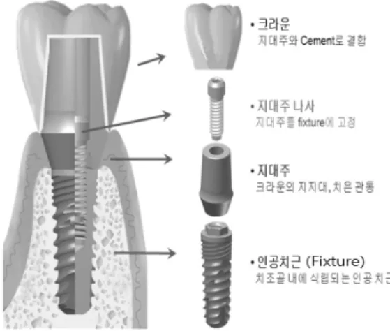
안정성이 요구된다. 생체 안정성 측면에서는 치조 골 내에서 거부 반응이 없도록 생체적합성 재료인 의료용 순수 티타늄을 사용하고 있다. 티타늄은 생체적합성 뿐만 아니라 강도적인 측면에서도 적 합한 강도를 가지면서 치조골과 근접한 탄성계수 를 가진 재료이다. 최근 임상에서의 시술 편의성 및 안전성을 도모하기 위해 다양한 시술 방법 및 기구들이 개발되고 있으나, 시술사례가 많아짐에 따라 인공치근과 지대주를 연결 고정하는 지대주 나사(screw)의 나사 풀림현상(screw loosening)으 로 인하여 인공치근 및 지대주가 파절되는 사례가 많이 보고되고 있다. fig. 1 는 지대주 나사 풀림 현상으로 인한 지대주 파절로 지대주를 제거하기 위해 지대주 나사의 상단부를 임의로 수정한 경우 의 예이다. 지대주 나사 풀림현상의 근본적인 원 인은 지대주 나사의 유지력 저하로 인한 미세한 움직임으로 인하여 발생을 한다. 임플란트를 사용 하는 기간동안 파절과 같은 문제가 발생하지 않게 하기 위해서는 지대주 나사의 풀림을 최소화 필요 가 있다. 이에 본 연구에서는 지대주 나사에 0.5mm Slot을 형성하여 지대주 나사 풀림현상을 방지하는 구조에 대한 연구를 수행하고자 한다.
Fig. 1 The example for dental implant abutment fracture by screw loosening
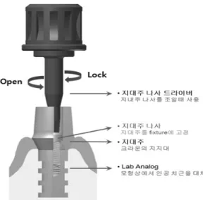
여 치과 및 기공소에서는 시술과정에서 fig. 3 와 같이 같은 지대주 나사를 10회 정도 조였다 풀었 다를 반복하게 된다. 이는 지대주 나사의 드라이 버 체결부 Hex의 변형을 가져온다. 지대주 나사 드라이버 체결 부분인 Hex 변형으로 인하여 구강 내에 최종 인공치아 보철물 장착을 위해 지대주 나사를 체결 시 원하는 조임 토크 값을 얻을 수 없게 된다. 따라서 지대주 나사는 덜 조이게 되어 최종적으로 지대주 나사 풀림현상 발생 및 인공치 근, 지대주의 파절이 일어나게 된다.
Fig. 2 Dental implant component
Fig. 3 Abutment screw contract diagram
2.2
임플란트 지대주 나사 디자인fig. 4 와 같이 치과용 임플란트 지대주 나사 상부의 육각면에 Slot을 1개, 3개를 형성하여 디 자인하고 그에 맞는 fig 5 의 지대주 나사 드라이 버를 디자인하였다.
Fig. 4 Abutment screw driver design
Fig. 5 Abutment screw head part design
2.3
시험편 제작fig. 2 와 같이 임플란트 지대주 나사 디자인은 Slot을 개수를 추가하여 디자인을하였으나, 시편 재현성이 낮고, 치수 정밀도 재현이 불안정하여 fig. 2 의 ‘b’ 시료를 육각 Hex의 대변 및 모퉁이 의 위치에 따라 시료를 제작하였다. 그 이유는 지 대주 나사와 지대주 나사 드라이버의 반복 체결 시 체결력이 전달되는 부위에 따른 지대주 나사풀 림 현상의 변화를 시험하고자 한다.
Fig. 6 Implant screw head part design (experimental/sample1-5, control group/ ‘O’company)
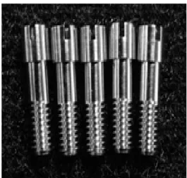
Fig. 7 Implant screw prototype
Fig. 8 Implant screw driver design
(experimental/sample1-3, control group/
‘O’company)
Fig. 9 Implant screw driver prototype
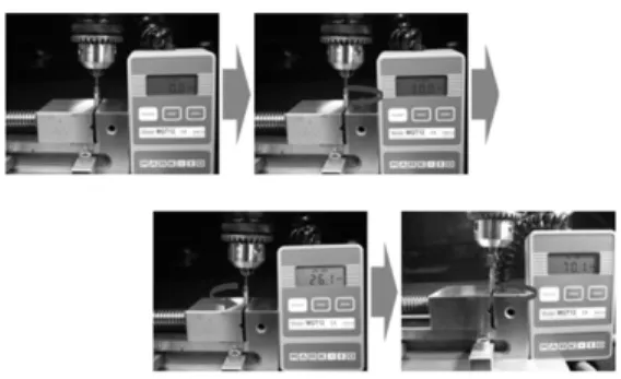
토크 값을 기록한다.
Fig. 10 Test of fracture torque value
2.5
지대주 나사 풀림 토크 값 실험① 고정체를 바이스에 고정, 지대주 및 지대주 나사를 고정체에 체결 한 후, 토크게이지를 지대 주 나사에 연결한다.
② 지대주 나사 조임 토크 값을 30Ncm으로 하여 지대주 나사를 조인다.
③ 지대주 나사를 30Ncm로 조인 후 5분 뒤 지 대주 나사를 푼다. 그 때의 토크 값을 측정하여 기록 한다.
④ ②, ③을 10회 반복 시험 한다.
⑤ 시험이 끝난 후 지대주 나사의 회전 전단강
도 평가를 위해 지대주 나사가 파절될 때까지 회
전 시킨다.
Fig. 11 Test of clamping force again after fracture torque value
2.6
지대주 나사 드라이버 Holding력 실험① 고정체에 지대주 나사를 체결한 후 지대주 나사드라이버를 지대주 나사에 5N의 힘으로 체결 한다.
② 드라이버를 잡다 당긴다.
③ 드라이버가 분리 되었을 때의 초대 load 값 을 측정하여 기록한다.
Fig. 12 Test of screw driver holding force
3. 실험결과 및 고찰
3.1
지대주 나사 Hex 부 파절 TorqueValue
실험결과지대주 나사 파절 강도는 Sample2 가 65.6Ncm로 대조군 ‘O’사 제품 57.46Ncm 대비 14%(8.14Ncm) 높게 측정 되었다. Sample 2의 경우 Slot 부분이
Close된 것이 Open된 것보 다 9%(5.58Ncm) 정도 높게 나타났다. 대조군 ‘O’사제품의 경우 지대주 나 사가 파절된 것이 아니라 지대주 드라이버가 파절되 었다.
Fig. 13 The result of fracture torque value to specimen
Fig. 14 The result of fracture torque value to table
3.2
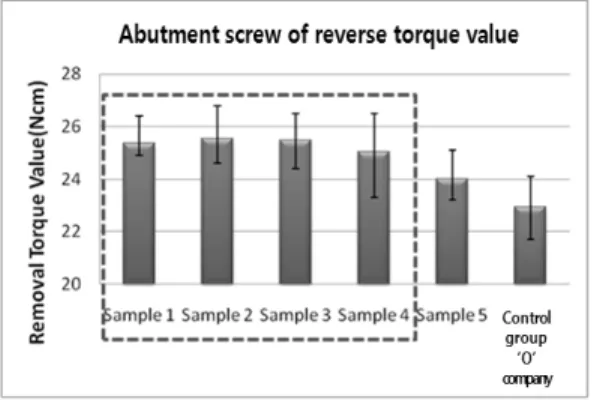
지대주 나사 풀림 토크 값 실험결과지대주 나사 풀림 토크 시험결과 Sample 1∼4
값은 약25Ncm로 비슷하게 측정 되었고, Sample
2의 경우는 조임 토크 대비 85%(25.56Ncm)의 풀
림 토크 값이 측정 되었다. 대조군 ‘O’사제품의
경우 조임 토크 대비 76%(22.94Ncm)의 풀림 토
크 값이 측정 되었다. (대조군 ‘O’사제품의 경우
최근 지대주 나사 안착부가 변경된 신제품으로
측정하였다.) Sample 2의 경우 풀림 토크 값이
의 Head 부의 변형을 방지하여 지대주에 체결되지 않은 상태의 파절 토크 값 보다 측정된 것으로 사 료 된다.
Fig. 15 The result of reverse torque value to specimen
Fig. 16 The result of reverse torque value to table
Fig. 17 The result of clamping force again after fracture torque value to specimen
Fig. 18 The result of clamping force again after fracture torque value to table
3.3
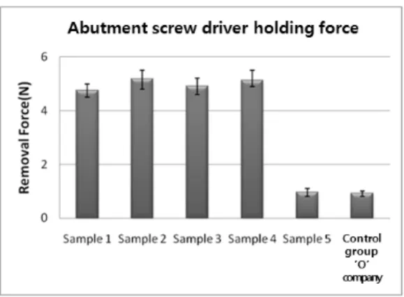
지대주나사 드라이버 Holding 실험결과지대주 나사 드라이버 분리력 값은 Sample 1∼4 의 경우 체결력 5N과 유사한 5N으로 비슷하게 측 정 되었다. 이는 지대주 나사와 드라이버 사이 접촉 면적 증대 및 끼임에 따른 분리력이 높은 것으로 판단된다.
Sample 2의 분리력 값은 대조군 ‘O’사제품 대
비 4.6배 높게 측정 되었다.
Fig. 19 The result of screw driver holding force to specimen
Fig. 20 The result of screw driver holding force to table
4. 결론 및 토의