• 검색 결과가 없습니다.

Effects of TiN Coating on the Fatigue Fracture of Dental Implant System with Various Cyclic Loads

N/A
N/A
Protected

Academic year: 2021

Share "Effects of TiN Coating on the Fatigue Fracture of Dental Implant System with Various Cyclic Loads"

Copied!
9
0
0

로드 중.... (전체 텍스트 보기)

전체 글

(1)

한국표면공학회지 J. Kor. Inst. Surf. Eng.

Vol. 48, No. 6, 2015.

http://dx.doi.org/10.5695/JKISE.2015.48.6.283

<연구논문>

ISSN 1225-8024(Print) ISSN 2288-8403(Online)

Effects of TiN Coating on the Fatigue Fracture of Dental Implant System with Various Cyclic Loads

Da-Un Jung

1

, Chae-Heon Chung

2

, Mee-Kyoung Son

2

, Han-Cheol Choe

3*

1

Prosthetic Dentistry, SMG-SNU Borame Medical Center, Seoul 61452, Korea

2

Department of Prosthodontics, College of Dentistry, Chosun University, Gwangju 07061, Korea

3

Department of Dental Materials, Research Center of Nano-Interface Activation for Biomaterials, &

Research Center for Oral Disease Regulation of the Aged, College of Dentistry, Chosun University, Gwangju 61452, Korea

(Received December 5, 2015 ; revised December 28, 2015 ; accepted December 29, 2015)

Abstract

The purpose of this study was to investigate effects of TiN coating on the fatigue fracture of dental implant system with various cyclic loads. TiN coated abutment screw, the fixture, and abutment of internal hex type were prepared for fatigue test. The fatigue test was carried out according to ISO 14801:2003(E) using tensile and compression tester with repeated load from 30% to 80% of static fracture force. Morphology and fractured surface was observed by field emission scanning electron microscope(FE-SEM) and energy dispersive X- ray spectroscope(EDS). The fracture cycle drastically decreased as repeated load increased. Especially, in the case of TiN-coated abutment screw, fracture cycle increased compared to non-coated abutment screw.

The fatigue crack was propagated fast as repeated load increased. The plastic deformation region decreased, whereas, cleavage fracture region increased as repeated load increased.

Keywords : Dental implant, Abutment screw; Fatigue; Ion plating, Fracture, Crack

1. Introduction

Recently, dental implant patients have increased significantly due to the aging. A dental implant has a screw connected with abutment and fixture. After fixation, it should be connected firmly without loosening or shaking between them

1-2)

. When repeated loads are applied to implant prosthesis in oral cavity, the screw is loosened and eventually a gap appears between prostheses. As the plaque deposition is occurred in the gap, the screw between fixture and abutment is fractured

3)

.

The fatigue fracture of implants is classified into two crack propagation stages: the first crack propagation stage is when already formed cracks are spread very slowly along the crystal plane where receives high shear stress

4)

and the second stage is when the growth rate of cracks increases very quickly. The two stage propagation processes

4)

have two patterns on the fracture surface such as beach mark and striation, which show the position of crack formation and propagation direction so studies on fracture surface observation receive attention. With these fracture patterns, the fatigue resistance of implant can be inferred.

Screw loosening causing the fracture is affected by roughness of screw surface and it appears when it is not able to contact fully to the screw surface due to the micro surface roughness. When the settlement effect is greater than elastic elongation of the screw, the contact force of the screw is lost and the screw loosening occurs

2,5)

.

* Corresponding Author : Han-Cheol Choe

Department of Dental Materials, Research Center of Nano- Interface Activation for Biomaterials, & Research Center for Oral Disease Regulation of the Aged, College of Dentistry, Chosun University

E-mail : [email protected]

*Da-Un Jung and Chae-Heon Chung equally dedica ted as

first author.

(2)

tually, elongation and loosening of fixing screw and facture lead to the fracture of implant fixture

7-9)

.

There have been a lot of studies carried out on the loosening of implant by repeated loads and tightening and on fatigue fracture. In addition, there are many studies on using functional materials such as WC, TiN, DLC, ZrN and etc

1,10)

for coating on the surface to prevent loosening, which can increase the effect of repeated tightening and loosening and can give the stability of surface and strength at the same time by minimizing the friction resistance due to low friction coefficient.

11-13)

However, studies on effects of these functional materials to the resistance of fatigue fracture through analysis of fracture surface, after fracturing the fixture and abutment screw using coated abutment are very limited

1,14)

And TiN coating on Ti-6Al-4V screw by PVD process improved the wear resistance and fatigue characteristics

15,16)

.

Therefore, in this study the suitability was examined after coating the abutment screw with TiN via ion- plating and tightening the abutment to the fixture, and effects of coating materials and cyclic loads on the resistance of fatigue fracture were examined through observing the cross section of fracture after performing the fatigue test according to ISO 14801.

2. Experimental details 2.1 Materials

2.1.1 Preparation of coated abutment screw and fixture

For the Ti-6Al-4V abutment screw used in this study, TiN coated (TiN Screw RP/Luna: by ion plating) and uncoated screws were prepared, manufactured by Shinheung MST Co., Ltd. and Fig. 1 shows an internal type Ti-6Al-4V fixture (Luna φ4.0 × 11.5 mm), abutment (Duo Abut. φ4.5G/H2.0 H5.5 Hex) and abutment screw used in this study, respectively. Fig. 1(a) shows an uncoated abutment screw, Fig. 1(b) shows TiN-coated abutment screw and Fig. 1(c) shows the abutment and fixture. When coated with TiN, abutment screw appears as golden color. The composition of

coating surface was examined using energy disper- sive x-ray spectroscopy (EDS; S-4800, Hitach, Japan).

2.2 Methods

2.2.1 Loosening and tightening experiment of TiN coated abutment screw

The abutment screw of implant system used in this study, which is manufactured with Ti-6Al-4V alloy, was prepared for 20 uncoated abutment screws as a control group and 20 TiN-coated abutment screws as an experiment group. Then, after tightening and loosening were repeated for 5 times, the fatigue fracture test was performed. 32 Ncm was applied as a locking force when tightening the screw to the fixture according to the company’s instructions for use and to maintain the constant locking force, the electronic torque controller (Brånemark system DEA 020 Torque controller) was used. The abutment screw was tightened and loosened after 10 sec passed and it was repeated 5 times under the same condition.

2.2.2 Observation of suitability of implant fixture and abutment screw

After connecting the implant fixture and abutment with an abutment screw by repeated loosening and tightening, it was buried with epoxy and after it was cut into a cross section using a cutter, fine grinding was implemented. Finely grinded cross section was observed for suitability using scanning electron microscopy.

2.2.3 Dynamic fatigue test of fixture and abutment screw

To exam the static compressive strength of fixture

and abutment screw, the compression load was

applied at 5 mm/min of head speed using tension and

compression tester (AG-10kNX, Shimadzu, Japan)

and the maximum fracture load was examined. The

maximum fracture load used in the experiment was

fixture. (a) non-coated abutment screw, (b) TiN-

coated abutment screw, (c) abutment and fixture.

(3)

average of 711 N as shown in Fig. 2. The repetitive load was set by selecting the maximum loads as the values of 80% (569N), 70% (498N), 60% (427N), 50% (356N), 40% (284N), and 30% (213N) from the maximum fracture loads, and the minimum loads as 10% of each, which are in the range of 56.9N~569N, 49.8N~498N, 42.7N~427N, 35.6N~356N, 28.4N~284N and 21.3N~213N. Repeated loads were applied by fixing the implant system to the dynamic materials testing machine (ADT-AV01k1, Shimadzu, Japan) at 30

o

of the gradient angle according to ISO 14801:

2003(E) regulations for dental implant fatigue test.

After fixing, the load condition which is the sine- type repeated load of minimum load and maximum load was applied to the upper part of the implant abutment at a cycle of 15 Hz. While maintaining constant temperature and humidity (temperature 25

o

C, humidity 40%), the final repeat cycle was given up to 5 million times which are corresponding to the average number of chewing time for about 20 years.

2.2.4 Observation of fatigue fracture of fixture The fatigue fractured surface of fixture was observed through a field emission scanning electron micros- copy (FE-SEM; S-4800, Hitach, Japan).

3. Results

3.1 Surface observation of abutment screw using scanning electron microscopy

Figure 3 is showing the uncoated abutment screw.

When looking at the structure picture from the screw thread (Fig. 3(a)) and the surface of the screw (Fig. 3(c)) of the abutment screw, the defects by mechanical processing which might occur during the milling processing are shown. Although it is a picture observed more than 3000X, the flat section between large scratches is shown in the surface of the screw.

As a result of examining the surface composition by EDS, the alloying elements, Ti, V and Al were detected (Fig. 3(e)). Fig. 3(b), (d) is the TiN coated surface using ion-plating taken with a scanning electron microscopy. It is showing that the coating materials are coated along the scratches occurred during processing in the thread of the screw (Fig. 3(b)).

In the surface of the screw (Fig. 3(d)), the coating particles are uniformly distributed, showing the coating is well done. From the result of EDS analysis on the screw surface (Fig. 3(f)), only nitrogen and Ti were detected, which means TiN coating was well performed.

Fig. 2. The schematic diagrams of cyclic loading apparatus and fixed specimen. (a) instrument of fatigue, (b) condition of ISO 14801, (c) fracture load under static compression test.

Fig. 3. FE-SEM and EDS micrographs showing the

non-coated(a,c,e) and TiN-coated(b,d,f) screw

surface. (a),(b) screw top (c),(d) screw flank

(e),(f) EDS.

(4)

these closely, it can be more evident by increasing the magnification (Fig. 4(a)). Fig. 4(b) shows the cross section observed via a scanning electron microscopy by connecting abutment to the fixture using TiN coated abutment screw through repeated loosening and tightening. Taken as a whole, the surface of the screw was well contacted at the upper part and the lower part uniformly but the crack was formed largely at the lower part of the screw, similar to uncoated sample.

3.3 Dynamic fatigue test results of fixture and abutment screw

Figure 5 depicits curves of load-cycle (Fig. 5(a), (d), (g)) displacement-cycle, (Fig. 5(b), (e), (h)), and

Fig. 4. FE-SEM micrographs showing the cross-sectional fitness between fixture. (a) non-coated (b) TiN- coated.

Fig. 5. The variation of load, displacement, and stress of non-coated abutment screw and fixture during cyclic fatigue

loading at 569N(a,b,c), 356N(d,e,f), and 213N(g,h,i).

(5)

46,346, 185,732, 3,459,321, 5,000,000, 5,000,000 cycles in order as repeated loads were decreased. The standard deviation was bigger as the repeated cycles were increased. Especially, from the relationship between displacement and the repeated cycles, the displacement tended to increase suddenly at the number that the fracture occurred.

Figure 6 presents curves of load-cycle (Fig. 6(a), (d), (g)), displacement-cycle (Fig. 6(b), (e), (h)), and stress-cycle (Fig. 6(a), (d), (g)) obtained after applying repeated loads to implant fixture using TiN coated abutment screw from 569 N load which is 80% of

fracture loads, to 213N which is 30% of fracture loads. The mean values of fatigue life were increased by 132,995, 113,540, 191,671, 5,000,000, 5,000,000, and 5,000,000 cycles compared to uncoated abutment screw as the repeated loads were decreased. Particularly, when 70% and 80% loads were applied, the fracture was occurred almost at the similar repeated cyclic number. This is summarized in Table 1.

3.4 Fractured surface of abutment screw and fixture

Figure 7 demobstrates the fractured surface observed Fig. 6. The variation of load, displacement, and stress of TiN-coated abutment screw and fixture during cyclic fatigue

loading at 569N(a,b,c), 356N(d,e,f), and 213N(g,h,i).

Table 1. The variation of fracture cycle according to load of non-coated and TiN-coated abutment screw and fixture Non-Coating Load (N) Failure cycle TiN-Coating Load (N) Failure cycle

80%-569N Specimen 46,471 80%-569N Specimen 132,995

70%-498N Specimen 46,346 70%-498N Specimen 113,540

60%-427N Specimen 185,732 60%-427N Specimen 191,671

50%-356N Specimen 3,459,321 50%-356N Specimen 5,000,000

40%-284N Specimen 5,000,000 40%-284N Specimen 5,000,000

30%-213N Specimen 5,000,000 30%-213N Specimen 5,000,000

(6)

by FE-SEM after fatigue fracture by applying cyclic loads at 569N, which is 80% of fracture loads, to the fixture connected using uncoated abutment screw.

The propagation of cracks was occurred from the lower part to the upper part (Fig. 7(a)) and suddenly fractured final fracture area was wide(marked by yellow line). On the surface where the initial cracks were propagated, the beach mark appeared (Fig. 7(b)) and the fatigue striation were observed (Fig. 7(c)) in this region. The striation interval is about 1.5 - 2.0 µm/cycle.

Figure 8 shows the fractured surface observed by FE-SEM after fatigue fracture by applying cyclic loads at 427N, lowering loads to 60%, using uncoated abutment screw. The crack propagation pattern was made from left to right. While progressing the plastic deformation the area where crack propagation

occurred and suddenly destroyed (Fig. 8(a)) is decreased compared to 80% and 70%. In the region of plastic deformation (Fig. 8(b)) the fine fatigue striation is shown (Fig. 8(c)). The interval of fatigue striation is fine striation smaller than about 1.0 µm/cycle.

Figure 9 presents the fractured surface observed by FE-SEM after fatigue fracture by applying cyclic loads at 569N, which is 80% of fracture loads, to the fixture connected using TiN coated abutment screw.

The crack propagation was occurred at 11 o’clock region toward 4 o'clock direction (Fig. 9(a)), the area where the crack propagation was occurred suddenly without plastic deformation was wide, similar to the uncoated abutment screw. In plastic deformation region, the fatigue striation was observed from the surface where the initial crack was propagated (Fig. 9(b)). However, the area where sudden fracture occurred (Fig. 9(c)) showed the cleavage fracture and thus, the fatigue striation was not observed. The striation interval was about 1.5 - 2.0 µm/cycle.

Figure 10 demonstrates the fractured surface observed by FE-SEM after fatigue fracture by applying cyclic loads at 427N, lowering loads to 60%, using TiN coated abutment screw. Cracks were propagated from 1 o'clock to 7 o'clock directions and the area of plastic deformation was wider and cleavage fracture area was significantly decreased (Fig. 10(a)). From the picture taken from the boundary of the plastic defor- mation area and cleavage fractured area, the presence and absence of fatigue striation appear distinctly (Fig. 10(c)). The interval of fatigue striation is fine striation smaller than about 1.0 µm/cycle.

Fig. 7. FE-SEM showing the fracture surface of fixture with non-coated abutment screw after fatigue test at 569 N: (a) overall, (b) fixture, (c) mag- nification of (b).

Fig. 8. FE-SEM showing the fracture surface of fixture with non-coated abutment screw after fatigue test at 427 N: (a) overall, (b) fixture, (c) mag- nification of (b).

Fig. 9. FE-SEM showing the fracture surface of fixture

with TiN-coated abutment screw after fatigue

test at 569 N: (a) overall, (b) fixture, (c)

magnification of (b).

(7)

4. Discussion

Recently, as patients who underwent dental implants are increased significantly, the clinical problem has occurred a lot. Particularly, fracture of the dental implant loses bone around the implant and it easily leads to the fracture. The recent research studies on cross section of the fracture revealed that the problem was caused by a fatigue fracture. The fatigue fracture

4)

of implant fixture is mainly caused by notch or scratch where the stress is concentrated, and these stress concentration place is occurred during mechanical processing and implant processing. The uniformity of fixture thickness during processing of internal screw is a factor to reduce the fatigue strength.

Therefore, in this study the suitability of internal screw was considered by coating TiN which can increase the fatigue resistance and surface phenomena of the fixture during fatigue fracture were examined.

The abutment screws used in this experiment were uncoated and TiN coated by ion-plating and it was to remove the defects occurred during milling processing from the thread of a screw and the surface. From high magnification, TiN coating had many scratches removed due to the coating effect. Therefore, because TiN coating to the screw has the best hardness and the wear resistance

17)

when the repeated loads were applied, it was able to remove

18)

the site where fatigue cracks could be spread (Fig. 3(b)). However, there were many large scratches in uncoated screws (Fig. 3(a)).

As a result of observing the suitability after fixing

the abutment to the fixture with TiN coated abutment screw, the screw surface had well contacted at the upper and lower parts uniformly (Fig. 4(a)), but in uncoated abutment screws, there was a big gap at the lower part of the screw surface, which can have the deviation of intervals due to the deviation from the processing of the screw thread. The particles in the gap can appear with the occurrence of wear particles as the thread is smeared during the process of repeated tightening and loosening for 5 times, and during the cutting process using a cutter to observe the cross section, if the gap is wide, it can be inserted but if it is focused mainly on the crushed thread

19)

, a lot of particles are present in the upper contact area (Fig. 4(a)) in uncoated abutment screw, but almost no particles are existed at the contact area (Fig. 4(b)) if coated with TiN. Therefore, it is considered that TiN coating is affected on the contact significantly.

When applying the repeated loads from 569N loads which is 80% of fracture loads, to 213N which is 30%, to the fixture and abutment screw, in all implant fixtures using both TiN coated and uncoated abutment screws the loads, displacement and stress are changing depending on the increase of repeated cycle and especially, the displacement is rapidly increased at the repeat cycles where the fracture occurs (Fig. 5, 6(b), e, h). The fatigue life increased from 46,471 cycle to 5,000,000 cycle if uncoated and from 132,995 cycle to 5,000,000 cycle if TiN coated when the repeated loads were decreased. Like this, low repeat cycle occurs in high loads and high repeat cycle occurs in low loads. This is because cracks occurred on the surface is propagated rapidly

1,14,19)

. However, if TiN coated, at 5,000,000 cycle which was the fracture number obtained by adding 50% of load the fracture was not occurred but if uncoated it was destroyed at 3,459,321 cycle, showing that the coating effect appeared noticeably in low loads (Table 1, Fig. 3). This is considered that as TiN removed the stress concentration site

1)

at low loads, crack propagation was somewhat delayed.

In the pre-researches, most of them is on the fracture of abutment screws

1,4,14)

and actually because the first crack is occurred from the fixture and propagated to abutment screw, it is thought to be able to know the role of crack stopping of abutment screw when considering the surface of the fixture.

For abutment screw, the fracture

14)

appeared during the crack propagation process is reported

14)

to have dimple fracture which is the surface of plastic defor- Fig. 10. FE-SEM showing the fracture surface of fixture

with TiN-coated abutment screw after fatigue

test at 427 N: (a) overall, (b) fixture, (c)

magnification of (b).

(8)

surface, which its final fracture area appeared widely (Fig. 7(a)). Also, the fatigue striation

4)

was well observed in plastic area (Fig. 7(c)), showing that the repeated loads were applied. TiN coated sample had no significant difference in the area of plastic deformation and suddenly destroyed area so TiN coating layer doesn't affect on the fatigue characteristics significantly in high loads for crack propagation stopping. The propagation rate in fatigue fracture can find with the fatigue striation interval where the initial crack is propagated in plastic deformation area, but for both uncoated and TiN coated it appears as 1.5 - 2.0 µm/

cycle which can be determined that the propagation rate

1)

is fast (Fig. 7, 9(c)).

When lowering the repeated loads to 70%, the propagation pattern of crack is similar to that in 80%

and the sizes of plastic deformation area and cleavage fracture area are slightly smaller or similar and the striation of beach marks is shown well as uniform intervals. The area mixed with plastic deformation surface and cleavage fracture area can be seen as semi-clevage

1,7)

and it was well differentiated.

As loads are lowering, crack propagation rate is slower and the interval of striation is about 1.0 µm/

cycle, which is reduced 2 times compared to 80% of fracture loads. When looking at the fractured cross section of the fixture connected using the TiN coated abutment screw, the cleavage fracture area decreases.

In case of using uncoated abutment screws, when load was applied as 427N of fatigue load by lowering more to 60%, the area where the crack propagation progressed but destroyed suddenly during plastic deformation (Fig. 8(a)) was smaller compared to 80% and 70%. The interval of fine fatigue striation (Fig 8(c)) decreased less than about 1.0 µm/cycle and the crack propagation rate was significantly decreased due to low loads. In case of using TiN coated abutment screws, the plastic deformation area became wider and the cleavage fracture area tended to be reduced significantly (Fig. 10(a)). The interval of fatigue striation had tiny striation than 0.5 - 1.0 µm/cycle so it could see that the propagation rate was decreased

affects on fatigue characteristics the improvement of the fixture

20)

.

5. Conclusions

To investigate the fatigue fracture of the implant fixture using titanium nitride coated abutment screw, the suitability and dynamic fatigue test were performed and the following conclusions were obtained.

As a result of examining the suitability of abutment screw and fixture, in TiN coating particles or debris occurred when tightening and loosening on the screw contact surface are smaller and it was well suited compared to uncoated abutment screw. With the increase of fatigue repeated loads, the number of fracture was significantly decreased and in TiN coating the effect of increasing fracture number is appeared significantly at low loads compared to uncoated sample. The propagation of fatigue cracks was faster as loads increase, and in TiN coating, the interval of fatigue striation was from 0.5 µm/cycle to 2.0 µm/cycle while in uncoated, it was increased significantly from 1.0 µm/cycle to 2.0 µm/cycle. As loads were increased, the area of plastic deformation was decreased and the cleavage fracture area was increased. The plastic deformation area was increased and the cleavage fracture area was decreased in TiN coating than uncoated sample.

In conclusion, TiN coated sample has lower pro- pagation rate of fatigue fracture in the fixture at the low repeated loads than uncoated sample, so it is thought that TiN coating treatment has an effect on the fatigue characteristics improvement of the fixture.

Acknowledgements

This study was supported by research fund from Chosun University Dental Hospital, 2014.

References

1. Y. H. Jeong, C. H. Lee, C. H. Chung, M. K. Son,

(9)

H. C. Choe, Surf. Coat. Technol., 243 (2014) 71.

2. Y. T. Jeong, C. H. Chung, H. T. Lee, J. Korean Acad Prosthodont, 39 (2001) 297.

3. G. A. Zarb, A. Schmitt, J. Prosthet Dent., 64 (1990) 185.

4. W. D. Callister, Materials Science and Engineering An Introduction, New York: Wiley, (2000).

5. R. L. Sakaguchi, S. E. Borgersen, Int J. Oral Maxi- llofac Implants, 10 (1995) 295.

6. A. l. Jabbari Y. S., Fournelle R., Ziebert G., Toth J., Iacopino A.M., J. Prosthodont, 17 (2008) 168.

7. W. J. Park, I. H. Cho, J. Korean Acad Prosthodont, 47 (2009) 424.

8. J. M. Kim, J. S. Han, S. Y. Lee, J. H. Yang, J.

B. Lee, Y. S. Kim, J. Korean Acad Prosthodont, 41 (2003) 519.

9. T. W. Lim, I. H. Cho, J. H. Lim, H. S. Lim, J.

Korean Acad Stomatognathic Func Occlusion, 18 (2002) 1.

10. M. Y. P. Costa, M. L. R. Venditti, M. O. H. Cioffi, H. J. C. Voorwald, Guimarães, V. A. Ruas, Int J Fatigue, 33 (2011) 759.

11. J. Y. Koak, S. J. Heo, I. T. Chang, S. H. Yim, J.

Y. Lee, K. R. Lee, J. Korean Acad Prothodont, 41 (2003) 128.

12. L. I. Chen, S. Q. Wang, Zhou S. Z., L. Jia, Y. Z.

Zhang, Int J Ref Met Hard Mater, 26 (2008) 456.

13. F. Clarysse, W. Lauwerens, M. Vermeulen, Wear, 264 (2008) 400.

14. R.W. Kim, H.S. Kim, H.C. Choe, M.K. Son, C.H.

Chung, Eng Procedia, 10 (2011) 1955.

15. D. Nolan, S.W. Huang, V. Leskovsek, S. Braun, Surf Coat Technol, 200 (2004) 5698.

16. E.S. Puchi-Cabrera, F. Matínez, I. Herrera, J.A.

Berríos, S. Dixit, D. Bhat, Surf Coat Technol, 182 (2004) 276.

17. J.F. Marco, A.C. Agudelo, J.R. Gancedo, D. Hanel, Surface and Interface Analysis, 27 (1998) 71.

18. G. Kuhn, B. Tavernier, L. Jordan, J Endod, 27 (2001) 516.

19. H. C. Choe, K. S. Hong, Y. M. Ko, B. O. Kim, J Kor Inst Met & Mater, 44 (2006) 400.

20. S. Baragetti, G.M. La Vecchia, A. Terranova, Int

J Fatigue, 27 (2005) 1541.L

수치

Fig. 2. The schematic diagrams of cyclic loading apparatus and fixed specimen. (a) instrument of fatigue, (b) condition of ISO 14801, (c) fracture load under static compression test.
Fig. 4. FE-SEM micrographs showing the cross-sectional fitness between fixture. (a) non-coated (b)  TiN-coated.
Figure 7 demobstrates the fractured surface observedFig. 6. The variation of load, displacement, and stress of TiN-coated abutment screw and fixture during cyclic fatigue
Figure 8 shows the fractured surface observed by FE-SEM after fatigue fracture by applying cyclic loads at 427N, lowering loads to 60%, using uncoated abutment screw

참조

관련 문서

With the increase of the dental implant procedure, there are many cases of Maxillary Sinus Floor Elevation Surgery(MSFES). Additionally, its side effect has

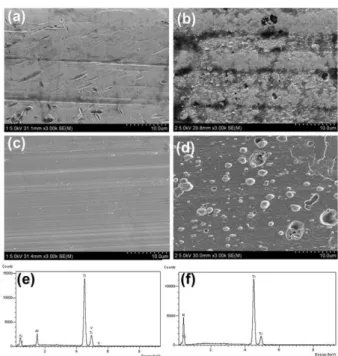
These results suggest that, the ZrN coated Ti-Nb alloy is a good corrosion resistance for dental implant compared with non-coated Ti-Nb alloy... The

Methods to overcome insufficient bone due to poor bone quality, the pneumatization of a maxillary sinus and other anatomical limitations of implant placement

A clinical study of the efficacy of gold-tite square abutment screws in cement-retained implant restorations.. An abutment screw loosening study of a Diamond

Histopathologic findings of control group at 4 weeks show little bone- implant contact (BIC) around the implant (asterisks) and new-bone formation in the defect

Measurement of proximal contact tightness between the left first molar and second molar(dental implant) in the mandible... Clinical dental anatomy, histology,

LIST OF TABLES... LIST

Evaluating parameters of osseointegrated dental implants using finite element analysis-a two- dimentional comparative study examining the effects of implant