< 목 차 >
Ⅰ. 서 론
Ⅱ. 연구재료 및 방법
Ⅲ. 연구성적
Ⅳ. 총괄 및 고안
Ⅴ. 결 론 참고문헌 사진부도 영문초록
I. 서 론
지난 몇 년동안 도재쟈켓관의 제작을 위한 새로운 재료와 과정에 대한 괄목한 만한 개발이 있었다. 도재 쟈켓관은 1886년, Land가 백금박 술식을 이용하여 제작한 것이 효시로써(34)1965년, 알루미나 보강 도재 관이 소개되면서(40)보다 널리 사용되게 되었다. 최근 에 개발된 것으로는 도재 쟈� 방식인 Cerestore, Alceram, Vita In-Ceram, Vita Hi-Ceram, Mirage와 주조유리-도재 방식인 Dicor, Cerapearl, IPS Empress, Olympus, Miraglass등이 있다.
전부도재관에 대한 관심이 지속적으로 집중되고 있
는 이유는 첫째, 전치부 수복을 위한 탁월한 심미성에 있다 도재전장금관에서는 금속구조로 인한 투명성의 결여 및 금속변연의 노출가능성이 있다. 둘재, 도재전 장금관을 위한 합금선택은 치과의사들에게 많은 혼동 을 초래하였다. 고금함유합금은 비교적 비싸고, 그 외 의 대체 금속 금속은 금속 알레르기, 도재와 금속간 결 합실패, 도재변색과 같은 단점이 있을수도 있다. 또한 이용가능한 합금의 종류가 대단히 많아서 귀금속 함량 만으로 임상적 적용을 위한 척도로 삼을 수는 없다.
주조유리-도재 방식은 Corning Glass Work사의 Stookey에 의해 개발되었는데(3)왝스 소환 방법으로 만든 유리 주조물을 적당히 열처리(ceramming)하여 조절된 결정화를 일으킴으로써 고강도, 열충격 저항등 의 독특한 성질을 부여하는 방법이다(3, 28). Dicor는 Grossman(27)과 Adair(1)의 연구에 기초를 둔 것으로 tetrasilicic fluoromica crystal(K2Mg5Si8O20F4)의 유연성과 판상형태에 의해 압축강도와 균열확산에 대 한 저항이 크고(26)회전 절삭기로 조정과 연마가 용이 한 장점이 있다. 또한 왝스 소환 방법을 사용함으로써 적합도가 우수(±0.5% 재현성)하고 정확한 교합형성 이 용이하며, 성분의 화학적 합성이 표준화되어 있어 조성성분이 항상 일정하다. 투명도의 깊이와 chameleon효과를 가지며(26) 치면 세균막에 대한 저 항성이 우수하고(26) 법랑질과 유사한 마모도, 방사선 투과성등을 갖는다.
- 대한 치과 보철학회지 Vol. 31 No. 2, 1993 -
Dicor와 수종 전장도재간의 전단결합강도
서울대학교 치과대학 치과보철학교실
류 경 희ㆍ이 선 형
그러나 Dicor는 과도한 투명도로 인해 노인치아나 심히 변색된 치아에서는 만족할 만한 결과를 얻을 수 없으며 특히 절단 1/3과 같이 심미성에 있어서 결정적 인 부위에서 문제가 있다(29, 38, 50). 또 Dicor는 표면 색 조형성방법에 의한 색조표현 재료로써, 원칙적으로 측 면분할 축조나 층 축조 술식을 사용하지 않도록 되어 있어 기공사의 예술적 능력이 제한된다(41).
사실 이런 문제를 해결하기 위한 시도는 1968년 MacCulloch에 의해 이미 시작되었다고 할 수 있다.
그는 핵화제로 감광성이 있는 은을 사용하고 냉각시 표면에 대한 자외선 조사율을 다르게 함으로써, ceramming시 치은연에서 절단연까지의 결정화가 다 른 비율로 되게 유도하여 투명도의 차이를 부여하였다
(35, 39). 최근에는 인공치관의 설측절단면을 삭제한 후
Dicor opaque를 채우거나(29, 50) 외면 전체를 백색 색 조도재로 도포하여(29, 38, 50)과도한 반투명도를 차단한 다든지, 협면을 0.5mm 삭제하거나(38) coping형의 Dicor관을 제작한 후(22)전장 도재를 축조하는 방법을 사용하고 있다.
Campbell은 전부도재관 계의 강도 비교에서 Dicor 주 조 체 (13,533psi)와 색 조 도 재 를 도 포 한 Dicor(11,848psi), Vitadur N으 로 전 장 한 Dicor(12,341psi)의 강도간에 통계적 유의차가 없다 고 하여 이의 타당성을 뒷받침했다(13).
이 술식에서의 전장도재로는 주로 알루미나성 도재 가 사용되었는데 Dicor와 알루미나성 도재의 열팽창 계수가 비슷하므로(7.2×10⁻⁶/℃, 6.8×10⁻⁶/℃)(38), 일반적인 인정을 받아왔다. Vitadur N과 De Trey’s NBK 1000 등이 여기에 해당된다.
최근에 Dicor의 전장도재로써 Dicor Plussystem 이 새로 개발되었다(21, 22). Judge는 열팽창뿐 아니라 열확산도에서도 Dicor와 유사하게 개발된 Dicor Plus system만을 사용할 것을 주장하고 있는 반면 (31, 38) Schmid등은 Dicor-Vitadur N, Dicor- NBk 1000, Dicor-Vivodent간의 화학적, 열적 적합 성 실험에서, 경계면에서의 물질간 이온 교환은 없었 으나 SEM상에서 모두 우수한 접촉양상을 보여주었고 열역학적 분석시 우수한 열적합도를 보여주었다고 주 장하였다(45).
물질간의 열적합도는 열팽차계수와 열전도도, 열확 산도등의 차에 의존하고 이것이 부적합도에 기인한 일 시적, 잔존 응력과 구강내 기능시 발생하는 기계적 힘 은 화학적 결합에 의해 어느 정도 저항될 수 있다. 미 국치과의사사회에서는 두 물질간 적합도를 인정받기 위해서는 열팽창 성적과 함께 열충격 시험, 결합강도 시험, 다중소성시 균열 존재시험중 2가지를 만족시킬 것을 요구하고 있고(17) 최근에는 Vickers경도 결각 시 험, 복굴절 시험, 유한요소 분석 법등도 많이 이용되고 있다.
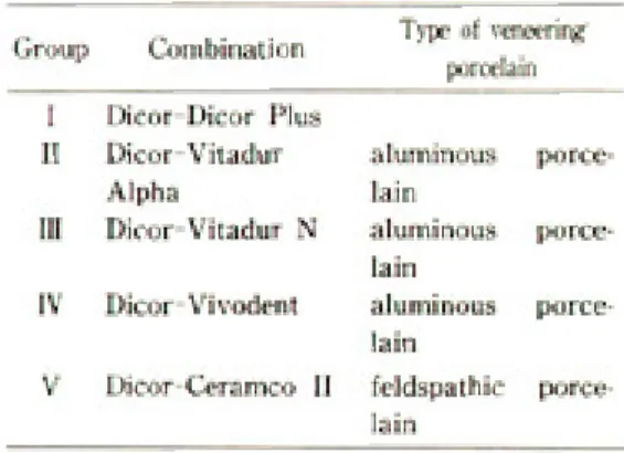
본 연구의 목적은 Dicor와 Dicor Plus, Vitadur Alpha, Vitadur N, Vivodent, Ceramco Ⅱ와 같은 전장도재간의 전단결합강도를 측정하고 주사전자현미 경에 의한 파절면과 경계면의 상태를 관찰함으로써 양 물질간의 적합도를 평가하는데 있다.
Ⅱ. 연구재료 및 방법
A. 연구재료
본 연구에 사용된 재료는 다음과 같다.
1. Dicor system(Dentsply/York Division, USA) 2. Dicor Plus dentin powder(Dentsply/York Division, USA)
3. Vitadur Alpha dentin powder(Vita Zahnfabrik, Bad sackingen, Germany)
4. Vitadur N dentin powder(Vita Zahnfabrik, Bad sackingen, Germany)
5. Vivodent dentin powder(Ivoclar, Schaan/Liechtenstein)
6. Ceramco Ⅱ dentin powder(Ceramco, Inc., East Windsor, NJ 08520)
B. 연구방법
1. 시편제작
왝스 소환 방법으로 총 55개의 Dicor 원판을 제작 하였다(지름 10mm, 두께3mm). Dicor시편의 한쪽면 을 600-grit silicone car-bide paper에 연마한 후
25㎛ aluminiumoxide로 40psi의 압력에서 grit blasting하였다. Dicor시편을 5군으로 나누고 다음의 각군에 대해 11개씩을 배정하였다.
Dicor시편을 초음파 세척한 후 지름 5mm, 높이 4mm의 종이튜브내에 혼합한 각 군의 전장도재를 채 운 다음 Dicor의 처리면 중앙에 놓고 진동과 흡수지에 의한 수분제거로 압축하였다. 끝이 뾰족한 기구로 결 합면에서의 과도한 전장도재를 제거하고, 컴퓨터화된
소성기계의 하나인 Alpha PC(Jelus International Corp. Hicksville. N.Y., USA)를 사용하여 각 제조회 사의 지시에 따라 소성하였다. 완성된 시편은 37℃ 물 에서 24시간 저장하고 5℃와 50℃ 사이에서 100번 thermocycling하였다(30초 잠금시간, 30초 이동시 간). 50개의 시편은 결합면이 기저면과 정확히 수직이 되도록 하고 Dicor의 처리면이 약간 튀어나오게 하여 가로 2.5cm, 세로 3cm, 두께 1cm 직육면체의 epoxy resin에 매몰하였다. 소성중의 수축을 고려하기 위하 여 결합면적은, 결합면에서의 전장도재 원통 최대와 최소 직경을 Verniercaliper(Mitutoyo, Japan)로 측 정, 평균치를 구하여 산출하였다. 각 군으로부터 1개 씩 임의로 선택한 시편은 결합부 경계면을 보기 위하 여 1.5cm변의 정육면체로 epoxy resin에 매몰한 후 저속 톱(Isomet, Buehler, USA)으로 절단하였다.
2. 전단결합강도 측정
50개의 시편은 각각 만능재료시험기(1125, Instron. Japan)상에 놓고 결합부위에서 약0.05mm 떨어진 지점에서 Dicor 평면과 평행하게 전단하중을 가하였다. Cross-head speed는 0.05cm/min, 최대 부하는 50kg으로 하였으며 시편이 최초로 분리되는 순간의 하중을 전단결합강도로 정하였다(Fig. 1).
Table 1. Combination of Dicor and veneering porcelain
Fig. 1. Diagram of shear testing device on a universal testing machine.
3. 주사전자현미경적 관찰
전단결합강도 측정후 파절양상과 절단시편의 경계 면을 관찰하기 위해 주사전자현미경(JSM-T2000, JEOL. Japan)을 사용하여 각각 15배, 1000배로 관찰 하였다(Fig. 2).
Ⅲ. 연구성적
Dicor에 대한 각 전장도재의 전단결합강도는 다음 과 같다(Table 2, Fig. 3).
Group Ⅳ의 경우 thermocycling중에 3개가 이미 탈락되었다.
전체적인 실험군간의 통계적 유의차를 비교하기 위 해 Tukey’s studentized range method를 사용하였 다(Table 3).
Dicor Plus, Vitadur Alpha, Vitadur N의 경우 Dicor와의 전달결합강도가 컸으며 서로간에 통계적 유의차는 없었다. Ceramco Ⅱ는 Dicor Plus에 비해 강도가 상당히 낮았으며 알루미나성 도재중 가장 낮은 Vivodent와는 유의한 차가 없었다.
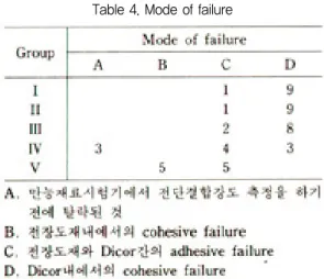
Dicor와 전장도재간 결합면의 파절양상을 주사전자 현미경으로 관찰한 결과는 다음과 같다(Table 4).
Fig. 2. Scanning electron microscope(JSM-T2000, JEOL, Japan)
Table 2. The shear bond strength between Dicor and veneering porcelains(MPa)
Fig. 3. The mean shear bond strength(MPa).
Table 3. Tukey’s studentized range(HSD) test
Ⅰ(Dicor-Dicor Plus), Ⅱ(Dicor-Vitadur Alpha), Ⅲ(Dicor-Vitadur N)군은 주로 Dicor내에 서의 cohesive failure였으며, Ⅳ(Dicor-Vivodent) 군은 thermocycling중에 이미 3개가 탈락하였고, adhesive failure와 Dicor내에서의 cohesive failure 가 대략 반반이었다. Ⅴ(Dicor-CeramcoⅡ)군은 전단 결합강도 측정전에 이미 모든 시편에서 방사상의 인장 성 균열을 보였고 결합실패의 양상은 adhesive failure와 CeramcoⅡ내에서의 cohesive failure가 함께 보였다.
Dicor와 전장도재간의 경계면에 관한 관찰은 Fig.9 에 나와 있다. Ⅰ군의 경우 경계부위를 구별할 수 없을 만큼 긴밀한 접촉이 이루어졌으며(Fig. 9a), ⅡⅢ군의 경우도 Ⅰ군보다는 못하나 비교적 만족할 만한 접촉을 유지하고 있었다(Fig. 9b, 9c). 그러나 Ⅳ군의 경우는 부분적인 틈을 보였고 Ⅴ군의 경우는 전경계면을 통해 지속적으로 큰 틈을 보였다(Fig. 9d, 9e).
Ⅳ. 총괄 및 고안
도재는 파절 가능성이 많으므로 이것을 포함하는 수 복물의 조합에서, 열적합도는 매우 중요하다. 열역학
적 응력은 두 물질간의 열팽창 및 수축의 차이나 열전 달 계수의 차이에서 오는데 이것의 존재는 두 물질간 의 열적합도에 의존한다. 일시적인 열 응력은 소성주 기동안 두 물질간의 열팽창계수가 일치하기 않기 때문 에 발생하나 소성주기동안의 건조한 상태에서 일어나 므로(9)균열이나 탈락등을 동반하지 않는다면 그다지 큰 문제가 되지는 않는다. Weiderhorn등에 의해 유 리같은 물질은 100% 습도에 노출시킨 후보다 건조한 조건에 있을 때가 훨씬 더 강하다는 것이 잘 입증되어 있다(49). 반면 잔존 열 응력은 소성의 전 온도범위에서 열팽창계수가 조화되지 않았거나 한 도재의 냉각속도 로부터 다른 도재의 열성이 바뀌었다든지 물질간 두께 비가 불규칙하기 때문에 발생하는데, 구강내 장착후 습도에 의한 static fatigue와 기능시의 기계적 힘에 의해 가중되어 결국은 수복물의 실패를 초래하게 된 다.
물질간 경계면에서의 응력(σ)는 1925년 발표한 Timoshenko의 물질간 응력 공식에 의해 표현될 수 있다(46).
α= k ΔαΔT k : 형태, 탄성계수를 고려한 상수 Δα: αcore- αveneer(α는 평균 열팽창계수) ΔT : Tg- TR (Tg는 유리전이온도, TR은 상온)
1981년 Fairhurst등은 이 식으로부터 적합지수(Ci) 를 유도하였는데 그것 역시 유리전이온도(Tg)와 함께 열팽창계수차에 기초를 두었다(23). 또 Anusavice등은 적합지수가 열충격 저항실험시의 열충격저항 ΔT와 상관관계가 있음을 입증했다(7).
물질간 열팽창 계수에 관한 일반적인 합의는 core 가 전장도재보다 약간 더 큰 열팽창 계수(α)를 가져서 전장도재에 약한 잔존 압축응력을 부여해야 한다는 것 이다. 만약 전장도재의 α가 더 커서 전장도재의 인장 응력을 유발하게 되면 압축강도에 비해 아주 약한 인 장강도(약1/50)를 갖는 전장도재에는 미세한 균열이 발생하게 된다. Anusavice 등은 유한요소분석을 통 해 열팽창계수차가(-) 부조화일때 잔존 인장력이 생길
Table 4. Mode of failure
것임을 추론했다(5). 반면 core의 α가 전장도재의 그것 보다 아주 커서 과도한 압축응력을 야기하는 경우는 경계면에서 전단력이 발생하여 결합이 파괴되게 된다.
외부로부터 전혀 자극이 없는 경우라면 물질간 열팽창 계수가 일치하는 것이 이상적일 것으로 보여지나 구강 내에서 지속적인 힘을 받게 되면 이것에 의해 전장도 재면에서 즉시 인장응력이 발생하게 되기 때문에 이 점을 고려해야 할 것이다.
도재의 의 열팽창 그래프는 금속과는 달리 곡선이 다. 이것은 온도가 올라갈때 두 물질간 길이차가 일정 한 비로 증가하는 것이 아니라 온도 범위에 따라 다르 게 증가함을 의미한다. 길이 차는 유리전이점에서 최 대에 도달하고 그 후로는 도재의 열팽창이 갑자기 증 가하여 두 물질간 길이차가 오히려 감소하게 된다. 두 물질이 고체대 액체로 있는 경우에는 응력이 완화되므 로 별 문제가 없으나 냉각시 전장도재가 그것의 열가 소적 유동성을 상실하고 점도가 증가하게 되면 열수축 부조화에 의해 유도된 응력을 저장하기 시작하므로 액 체에서 고체로 전환되는 Tg는 중요한 의미를 갖는다.
물론 냉각 속도, 소성 횟수등에 따라 α나 Tg등이 변 하긴 하지만(11, 24)임상적 경험에 의해 두 물질간 열적 합도의 허용가능한 범위가 있음이 일반적으로 인정되 고 있다. 그러나 열팽창차의 상한은 명확하지 않는데 도재가 압축에 대해서는 비교적 강하기 때문이다. 만 약 수복물이 정확한 core 형태, core와 전장도재간의 두께비, 정확한 소성계획등의 모든 요구 조건을 만족 한다면 균열이 일어나지 않으나, 이런 요구조건이 만 족되지 않거나 심지어 약간의 실패만 있어도 쉽게 균 열이 일어날 것이다. 따라서 과도한 압축하에서도 균 열없이 결합할 수 있는 열팽창차의 상한은 차라리 넓 은 범위라고 할 수 있을 것이다. 반면 열팽창차의 하한 은 비교적 명백한데 도재가 인장응력에는 극도로 약하 여 아주 미소한 인장응력에 의해서도 쉽게 균열이 일 어나기 때문이다.
Walton과 O’Brien은 α가 core보다 7% 더 작은 전 장도재는 균열되지 않았으나 4% 더 큰 것은 균열되었 다고 하였고(48), Anusavice등은 core보다 5.5% 더 작 은 α를 가진 전장도재는 균열하지 않았으나 4%더 큰
것은 균열하였다고 보고하였다(6). α부적합도의 상한 을 처음으로 결정한 사람은 Cascone과 Nabatran이 었는데 그들은 전장도재의 α범위가 core보다 7%작 거나 1% 큰 경우에 균열이 일어난다고 주장하였다(15). 또 Yamamoto는 열팽창차에서 상한은 0.21%, 하한 은 0.02%가 난전한다고 했으며(-)부조화인 경우는 시 도하지 말 것을 충고하고 있다(47). 현재의 상업용품들 은 α부조화의 허용가능치를 1×10⁻⁶/℃ 이하로 조정 하고 있다(47). Schmid 등의 측정에 의하면 Dicor 8.02×10⁻⁶/K, Vitadur N 7.27×10⁻⁶/K, Vivodent 6.91×10⁻⁶/K Vivodent의 경우는 약간의 문제가 있 음이 발견된다. 또 열팽창 곡선에서도 유리전이온도, 유리연화온도에서 Vivodent의 경우가 Dicor와 가장 차이가 많이 난다(45). αdata의 절대값은 매우 작고 예 민하여 장치, 방법, 측정조건 뿐 아니라 술자에 따라서 도 변하기 때문에 어떤 참고문헌으로부터의 data를 다른 것의 것과 비교하는 것은 문제가 있지만 Ceramco Ⅱ의 경우는(-)부조화(α: 12.0×10⁻⁶/℃)(25) 가 매우 크므로 도재전장금관용은 Dicor의 전장도재 로는 부적합한 듯하다.
결합강도 시험이 α부조화의 효과를 조사하기 위해 서 흔히 사용되어왔는데, Rowe와 Asgar는 α부조화 와 결합강도간에 관계가 없다고 하였으나(44) Coffey등 은 상관관계가 있음을 증명하였다(16).
그러나 이러한 응력과 관련된 적합도의 분석은 온전 한 탄성체를 가정한 것이다. 그들은 유리전이온도위에 서는 응력이 완전히 완화되고 아래에서는 전혀 되지 않는 것으로 가정하였다. 이런 가정은 잘못된 것이며 새로와져야 한다. Rekhson과 Mazurin(43), Hsuch와 Evans(30)등이 응력 완화의 개념을 처음으로 포함시켰 는데 그들은 적합도가 양 물질간의 두께비에 의존한다 고 하였다. 즉 한 물질의 그것에 대해 달라지면 상대적 인 stiffness가 변하게 되어 응력 완화와 함께 일시적 인 열응력이 달라진다는 것이다. Bertolotti와 Fukui 는 유리전이온도에서, 점성상태에서 탄성상태로 갑자 기 변화하는 것으로 보는 것보다는 응력 완화가 점차 로 감소하는 것으로 보는 것이 더 타당하다고 주장하 였다(10). Bertolotti와 Fukui가 이런 유리전이범위와
응력완화를 포함하여 계면 응력을 계산하였고(10) Bertolotti가 마침내 측정값과 예상값의 일치를 얻었 다.
응력완화면에서 볼때 열전달계수인 열전도도와 열 확산도는 매우 중요하다. 열은 전장도재를 통해 상실 되므로 전장도재의 열전도도나 열확산도가 클수록(심 지어 core보다) core가 열을 빨리 상실하여 결합면부 터 먼저 냉각, 경화 되므로 응력이 완화될 수 있다(47). Dicor와 알루미나성 도재는 열전도도에서는 비슷하나 열 확 산 도 에 서 는 차 이 가 있 는 데 (Dicor 0.800mm/sec(19, 28), 알루미나성 도재 0.660mm/
sec(42), 장석도재 0.640mm/sec(2)), 비록 alumina 입 자의 함량증가에 따라 열확산도가 증가한다는 보고는 있으나(42) 알루미나성 도재 dentine의 여우는 alumina의 양이 그다지 많지않고 따라서 열확산도의 크기도 별로 크지 않다. Braden은 재료를 통해 열이 통과하는 율인 열확산도가 steady-state의 열전도도 보다 더 중요하다고 하였다(12).
그 외, 물질간의 결합강도에 기여하는 요인으로서 는 wettability와 Dicor표면의 요철, 화학적 결합등을 들 수 있다. Sand blasting에 의한 거시적 요철은 결 합표면적을 증가시켜 기계적 결합강도를 증가시키나 과도하면 결합부위에서의 응력집중과 기포형성을 초 래하여 오히려 결합력을 감소시킬 수 있다(32). 우수한 wettability 는 이것을 어느정도 보상하며, 물질간의 거리를 분자결합이 가능한 만큼 가깝게 하여 화학적 결합을 시작하는데도 기여할 수 있다. 본 실험에서 Vitadur Alpha, Vitadur N의 경우 비교적 우수한 wet양상을 보여주었는데 이는 Schmid등의 연구결과 와 일치한다. 그러나 그는 EPMA조사결과, 계면에서 의 이온교환의 증거를 발견할 수 없었다고 한다(45). 반 면 Dicor Plus의 경우는 아주 우수한 wet양상을 보여 주었으며, Dicor와 색조도재간의 화학적 결합을 고려
할 때(29, 36)화학적 결합도 기대된다고 할 수 있다.
본 실험결과에서 전단결합강도의 절대치는 비교적 낮았으나, Dicor Plus, Vitadur Alpha, Vitadur N 의 경우 파절양상이 주로 Dicor의 약한 인장강도에 기 인한 Dicor내에서의 cohesive failure인 것을 감안할
때 이들의 실제 전단결합강도는 측정치보다 더 클 것 으로 기대된다.
하중속도, 응력분산유형, 물질간 두께비(18)뿐 아니 라 결합면의 길이와 넓이(33)마저도 결합강도의 크기뿐 아니라 파절 시작점의 위치와 균열 확산의 경로에 영 향을 미칠 수 있기 때문에, 실험에서 측정한 전단결합 강도의 절대치에 큰 의미를 둘 수는 없겠으나 상대적 인 비교는 가능하다. 본 실험결과로 미루어 보아 Dicor의 전장도재로는 Dicor Plus가 가장 우수하고 장석도재는 불량한 것으로 나타났으나 알루미나성 도 재중 Vitadur Alpha, Vitadur N의 경우 Dicor Plus 에 비해 유의할 만한 차이는 나타나지 않았다. 따라서 Dicor Plus가 가장 추천되며 알루미나성 도재의 경우 에는 열팽창계수, 열전달계수등에서 가능한 한 조화되 는 것을 쓰되 core의 설계, 두께비, 수복물의 크기, 열 조건등에서 더 엄격한 주의가 필요하다고 사료되는 바 이다.
Ⅴ. 결 론
저자는 Dicor와 수종의 전장도재간의 전단 결합강 도를 비교하기 위해 Dicor-Dicor Plus, Dicor- vitadur Alpha, Dicor-vitadur N, Dicor- Vivodent, Dicor-Ceramco Ⅱ의 5군에 대해 11개씩 의 시편을 제작한 후 만능재료 시험기로 전단결합강도 를 측정하고 주사전자현미경상에서 파절면과 두 물질 간의 계면을 관찰한 결과 다음과 같은 결론을 얻었다.
1. 평 균 전 단 결 합 강 도 는 Dicor-Dicor Plus(10.53Mpa), Dicor-vitadur Alpha (8.84Mpa), Dicor-vitadur N(7.37Mpa), Dicor-Vivodent(4.28Mpa), Dicor-Ceramco
Ⅱ(0.089Mpa)의 순이었다.
2. Dicor-CeramcoⅡ의 경우 Dicor-Dicor Plus 에 비해 강도가 상당히 감소하였으나(P<0.01), Diocr-vivodent에 비해서는 유의한 차가 발견 되지 않았다(p>0.01).
3. Dicor-Vitadur Alpha, Dicor-vitadur N의 경우 Dicor-Dicor Plus에 비해 유의한 차가 없 었다(p>0.01)
4. 파절면을 주사전자현미경으로 관찰한 결과 Dicor-Dicor Plus, Dicor-vitadur Alpha, Dicor-vitadur N은, Dicor내에서 cohesive failure를 보였으며, Dicor-Vivodent는 adhesive failure를 보였으며, Dicor- CeramcoⅡ는 adhesive failure와 CeramcoⅡ 내에서의 cohesive failure가 함께 나타났다.
5. 경계면을 주사전자현미경으로 관찰한 결과 Dicor-Dicor Plus의 경우, 가장 우수한 접촉을 보였으며, Dicor-Vitadur Alpha, Dicor- Vitadur N도 비교적 우수한 접촉을 보인 반면 Vivodent는 부분적인 틈을, CeramcoⅡ는 지 속적인 상당한 틈을 보였다.
Reference
1) Adair PJ, Bell BH, Pameijer CH. Casting technique of machinable glass ceramics. J Dent Res 59 : 475,1980.
2) Adair PJ, Grossman DG. The castable ceramic crown. Int J Periodontol. Res Dent 2 : 33-45, 1984.
3) Anon., Corning develops new ceramic materials.
Am Ceram Soc Bull 36(7) : 279-80,1957
4) Anusavice KJ. Screening tests for metal-ceramic systems. P371-414. IN McLean JW Dental Ceramics. Proceedings of the First International Symposium on ceramics. Chicago : Quintessence Publ. Co., Inc., 1983
5) Anusavice KJ, DeHoff PH, Fairhurst CW.
Comparative evaluation of ceramic-metal bond tests using finite element stress analysis. J Dent Res 59 : 603-13,1980.
6) Anusavice KJ, DeHoff PH, Gray A.Lee RB.
Delayed crack propagation in porcelain due to
incompatibility stress [Abstract]. J Dent Res 65 : 343,1986.
7) Anusavice KJ, Twiggs SW, DeHoff PH, Fairhurst CW. Correlation of thermal compatibility data for porcelain-metal systems. J Dent Res 34 : 419- 22,1982
8) Bertolotti RL. Calculation of interfacial stress in poreclain-fused-to-metal systems. J Dent Res 59 : 1972-7,80.
9) Bertolotti RL. Porcelain-to metal bonding and compatibility. P415-29. In McLean JW Dental Ceramics. Proceedings of the First International Symposium of Ceramics. Chicago : Quintessence Publ. Co., Inc., 1983.
10) Bertolotti RL, Fukui H. Measurement of softening temperature in dental bake-on- porcelains. J Dent Res 61 : 480-3, 1982.
11) Binns D. The chemical and physical properties of dental porcelain. P 41-82 : In McLean JW Dental Ceramics. Proceedings of the First International Symposium of Ceramics. Chicago : Quintessence Publ. Co., Inc., 1983.
12) Braden M Heat conduction in teeth and the effect of lining materials. J Dent Res 43 : 315-22, 64.
13) Campbell SD. A comparative strength study of metal ceramic and all-ceramic esthetic materials : Modulus of rupture. J Pros-thet Dent 62 : 476- 9, 1989
14) Cascone PJ. Effect of thermal properties on porcelain-to metal compatibility. IADR progr &
Abst 58 : NO.683, 1979
15) Cascone PJ, Nabatran D. Determination of thermal expansion compatibility limits for porcelain-metal systems [Abstract]. J Dent Res 61 : 330, 1982.
16) Coffey JD, Anusavice KJ, DeHoff PH. Lee RB, Hojjatie B. Influence of contraction mismatch and cooling rate on flexural failure of PFM systems. J Dent Res 67 : 61-5, 1988.
17) Council on Dental Materials, Instruments and Equipment. Porcelain-metal alloy compatibilities : criteria and test methods. J Am Dent Assoc 102 : 71-2, 1981.
18) DeHoff PH, Anusavice KJ, Hathcock PW Evaluation of four point flexure test as a measure of metal-ceramic bond strength. J Dent Res 59B : Astract No. 34, 1980.
19) Dentsply/York Division. Clinical instruction for Dicor restorations and use of the dicor light activated cementation kit. York, Pa. : Dentsply International Inc., 1988.
20) Dentsply/York Division. Dicor : Laboratory technique manual. York, Pa. : Dentsply International Inc., 1984.
21) Dentslply/York Division. Dicor plus. York, pa. : Dentsply International Inc., 1990.
22) Dentsply/York Division. Dicor plus porcelain system technique manual. York, Pa. : Dentsply International Inc., 1989.
23) Fairhurst CW, Anusavice KJ, Ringle RD, Twiggs SW. Porcelain-metal themal compatibility. J Dent Res 60 : 815-9, 1981.
24) Fairhurst CW, Hashinger DT, Twiggs SW. Glass transition temperature of dental porcelain. J Dent Res 60 : 995-8, 1981
25) Fan PL, Stanford JW. Ceramics : Their place in dentistry. International Dental Journal. 37 : 197- 200, 1987.
26) Grossman DG. Cast glass-ceramics. Dent Clin North Am. 29(40) : 725-739, 1985.
27) Grossman DG. Machinable glass-ceramics based on tetrasilicic mica. J Am Ceram Soc 55(9) : 446- 49, 1972.
28) Grossman DG. Processing a dental ceramic by casting methods. Research and development division Corning Glass Works, Corning, New York, 1987.
29) Hensel W, Sato T, Wohlwend A, Schäer P. A
clinical case report utilizing a castable ceramic crown system. Quintessence International 18(5) : 323-35, 1987.
30) Hsuech CH, Evans AG. Residual stresses in metal/ceramic bonded strips. J Am Ceram Soc 68 : 241-8, 1985.
31) Judge S. Ceramics in clinical dentistry. Brit Dent J May 7. 1988.
32) Kelly N, Asgar K, O’Brien JJ. Tensile strength determination of the interface between porcelain fused to gold. J Biomed Mat Res 3 : 403,1969.
33) Koji K. Bond strength between nonprecious metal alloy and porcelain. Part 1. Bond strength with press condensing method. J Japan Soc Dent.
Appar. And Mat. 17 : 112, 1976.
34) Land C. Porcelain dental arts. Dent /Cosmos 45(8) : 615-20, 1903.
35) MacCulloch WT. Advances in dental ceramics.
Brit Dent J 125 : 361, 1968.
36) Malament KA. The cast glass-ceramic crown. P 331-42. In Preston JD Perspectives in Dental Ceramics. Proceedings of the Fourth International Symposium on Ceramics : Quintessence Publ. Co., Inc., 1988.
37) Malament KA, Grossman DG. The cast glass- ceramic restoration. JPD 57(6) : 674-83, 1987.
38) McLean JW. Ceramics in clinical dentistry. Brit Dent J 164 : 187-94, 1988.
39) McLean JW. The future for dental porcelain. pp.
13 In McLean JW. Dental Ceramics. Proceeding of the Fist International Symposium on Ceramics.
Chicago : Quintessence Publ. Co., Inc., 1983.
40) McLean JW, Hughes TH. The reinforcement of dental porcelain With ceramic oxides. Br Dent J 119(6) : 251-67, 1965.
41) McLean JW, Kedge4 MI. High-strength ceramics. Quintessence International 18 : 2 : 97- 106, 1987.
42) Piddock V. Effect of alumina concentration on
the thermal diffusivity of dental porcelain. J Dent Res 17(6) : 290-4, 1989.
43) Rekhson SM, Mazurin OS. Stress relaxation in glass and glass-to-metal seals. Glass Tech 18 : 7-14, 1977.
44) Rowe A, Asgar K. Thermal studies of porcelain substrate metals [Abstract]. J Dent Res 55 : 505, 1976.
45) Schmid M, Fischer j, Hoffmann C, Strub JR.
Chemische und thermische kompatibilitat vollkeramischer verbundsysteme. Dtsch Zahnarztl Z 45(8) : 505-8, 1990.
46) Timoshenko S. Analysis of bi-metal thermostats.
J Opt Soc Am 11 : 233-5, 1925.
47) Yamamoto M. Factors affecting the strength to metal-ceramics; thermal expansion. Metal Ceramics : Principles and methods of Makoto Yamamoto. Quintessence Publ. Co., Inc., 157- 202, 1985.
48) Walton TR, O’Brien WJ. Thermal stress failure of porcelain bonded to a palladiumsilver alloy. J Dent Res 64 : 476-80, 1985.
49) Weiderhorn SM. A chemical interpretation of static fatique. J Am Cer Soc. 55 : 81, 1972.
50) Wohlwend A, strub JR, Schäer P. Metal ceramic and all-porcelain restorations : cur-rent considerations. Int J Prosthodont 2 : 13-26, 1989.
EXPLANATION OF FIGURES
Fig. 4. SEM photomicrograph showing cohesive failure within Dicor in case of Dicor-Dicor Plus(x15).
a) Dicor Plus side b) Dicor side
Fig. 5. SEM photomicrograph showing cohesive failure within Dicor in case of Dicor-Vitadur Alpha(x15)
a) Vitadur Alpha side b) Dicor side
Fig. 6. SEM photomicrograph showing cohesive failure within Dicor in case of Dicor-Vitadur N(x15).
a) Vitadur N side b) Dicor side
Fig. 7. SEM photomicrograph showing adhesive failure in case of Dicor-Vivodent(x15).
a) Vivodent side b) Dicor side
Fig. 8. SEM photomicrograph showing adhesive failure and cohesive failure within CeramoⅡ in case of Dicor-CeramcoⅡ(x15).
a) CeramcoⅡ side b) Dicor side
Fig. 9. SEM photomicrograph showing the interface(x1000).
a) Dicor-Dicor Plus b) Dicor-Vitadur Alpha c) Dicor-Vitadur N d) Dicor-Vivodent
논문사진부도 ①
논문사진부도 ②
=Abstract=
THE SHEAR BOND STRENGTH BETWEEN DICOR AND SEVERAL VENEERING PORCELAINS
Kyung-Hee Ryoo. D.D.S., Sun-Hyung Lee, D.D.S., M.S.D., Ph. D.
Department of Prosthodontics, College of Dentistry, Seoul National University