Korean J. Mater. Res.
Vol. 27, No. 9 (2017)
495
Influence of Electrolytic KF on the Uniform Thickness of Oxide Layers Formed on AZ91 Mg Alloy by Plasma Electrolytic Oxidation
Duck-Hyun Song 1 , Dae-Young Lim 2 , Vladimir Fedorov 3 and Jeong-Hwan Song 2†
1Dept. of Materials Engineering, Graduate School of PaiChai University, Daejeon 35345, Republic of Korea
2Dept. of Materials Science and Engineering, PaiChai University, Daejeon 35345, Republic of Korea
3Nikolaev Institute of Inorganic Chemistry, Russian Academy of Sciences, Novosibirsk 630-090, Russia
(Received July 14, 2017 : Revised August 11, 2017 : Accepted August 24, 2017)
Abstract
Oxide layers were formed by an environmentally friendly plasma electrolytic oxidation (PEO) process on AZ91 Mg alloy. PEO treatment also resulted in strong adhesion between the oxide layer and the substrate. The influence of the KF electrolytic solution and the structure, composition, microstructure, and micro-hardness properties of the oxide layer were investigated. It was found that the addition of KF instead of KOH to the Na2SiO3 electrolytic solution increased the electrical conductivity. The oxide layers were mainly composed of MgO and Mg2SiO4 phases. The oxide layers exhibited solidification particles and pancake-shaped oxide melting. The pore size and surface roughness of the oxide layer decreased considerably with an increase in the concentration of KF, while densification of the oxide layers increased. It is shown that the addition of KF to the basis electrolyte resulted in fabricating of an oxide layer with higher surface hardness and smoother surface roughness on Mg alloys by the PEO process. The uniform thickness of the oxide layer formed on the Mg alloy substrates was largely determined by the electrolytic solution with KF, which suggests that the composition of the electrolytic solution is one of the key factors controlling the uniform thickness of the oxide layer.Key words
plasma electrolytic oxidation, AZ91 Mg alloy, surface treatment, KF, uniform thickness.1. Introduction
Mg and its alloys have been used for many appli- cations, including communications and computer parts
1,2)owing to their excellent physical and mechanical properties, such as low density, high specific strength, good castability, good welding ability, good electrical conductivity, high thermal conductivity, high dimensional stability, and good electromagnetic shielding characteristics.
3-5)However, the main factor limiting the broad application of Mg alloys is their high rate of corrosion, poor friction reduction, and low hardness.
6,7)Therefore, it is necessary for surface treatments to protect the metal and its alloys. Plasma electrolytic oxidation(PEO) is a surface treatment method to form oxide layers on Mg alloys using an environ- mentally friendly process.
8)The dense and hard PEO coating contributes to improving the wear and corrosion resistance on the surface of Mg alloy. The thickness and structure of oxide layer formed by the PEO process
depend on various processing conditions, such as chemical composition and concentration of electrolyte, operating electrical parameters, and composition of metal sub- strate.
9,10)The chemical composition and concentration of electrolyte exert considerable influence on the thickness and formation of oxide layers on Mg alloys. Increasing the concentration of KOH enhances the electrical con- ductivity of the electrolyte and helps adjust the pH of the electrolyte. The concentration of the KOH electrolyte is highly related to sparking behavior during surface treat- ment in that the breakdown voltage linearly increases.
11)Previous research showed that the addition of compounds containing F
−ions into the electrolyte solution helped increase the electrolyte conductivity.
8)In this study, the influence of KF introduced as an additive to enhance the electrical conductivity in the electrolytic solution for the PEO process of AZ91 Mg alloy was investigated. The structures, morphologies, thick- nesses, hardnesses, and chemical compositions of the
†
Corresponding author
E-Mail : [email protected] (J. H. Song, PaiChai Univ.)
© Materials Research Society of Korea, All rights reserved.
This is an Open-Access article distributed under the terms of the Creative Commons Attribution Non-Commercial License (http://creative-
commons.org/licenses/by-nc/3.0) which permits unrestricted non-commercial use, distribution, and reproduction in any medium, provided the
original work is properly cited.
496 Duck-Hyun Song, Dae-Young Lim, Vladimir Fedorov and Jeong-Hwan Song
oxide layer on the AZ91 Mg alloy were evaluated.
2. Experimental Procedure
Squares (45 mm × 45 mm × 1 mm) of AZ91 Mg alloy (chemical composition: Al 8.5-9.5 %, Zn 0.45-0.90 %, Mn 0.15-0.40 wt%, and Mg balance) were used as substrates. Prior to PEO treatment, the specimens were polished using SiC abrasive paper (with two grades: 800 and 1200 grit), degreased in ethanol and acetone, and dried with warm air. Mg alloy specimens and stainless steel plates were used as anodes and cathodes, respect- ively. The treatments were executed at constant current density (5.8 A/dm
2) and constant ratio of anode to cathode current (Ia/Ic = 1.11) using a pulsed bipolar current power supply of 650 V/25 A capacity (HF1, ZAO Nikom, Russia). The PEO process was maintained at a frequency of 500 Hz and a duty cycle of 10 % for 30 min. The temperature of the electrolyte was maintained at 25-30
oC using a water cooling system during surface treatment.
Table 1 lists the chemical compositions of electrolytes used in this study for PEO treatment. After PEO treat- ment, the specimens were taken out from the electrolytes, washed using distilled water, and dried with warm air.
The phase compositions and crystal structures of oxide layers were investigated using X-ray diffraction (XRD, CuK α, Fine Tube, 40 kV-40 mA, Rigaku, Japan). The microstructures of the oxide layer surfaces and polished cross-sections were studied using field emission scanning electron microscopy (FE-SEM, Hitachi S-4200, Japan).
The distributions of the component elements across the polished cross-sections were also analyzed using energy dispersive X-ray spectroscopy (EDS, Bruker AXS #4010 XFlash Detector) attached to the SEM. We could directly measure the thicknesses of the oxide layers from the SEM images of the polished cross-sections and a digital thickness meter (PosiTector 600, USA). The outer porous layer of oxide layer was removed by abrasion with SiC paper. The micro-hardnesses of the oxides were measured on a Vickers hardness meter (Matsuzawa, MMT-7, Japan) at a load of 100 gf for a loading duration of 10 s. The final micro-hardness value quoted is the average of 10 replicate measurements. The hardness of the Mg alloy substrate was measured in the same manner.
3. Results and Discussion
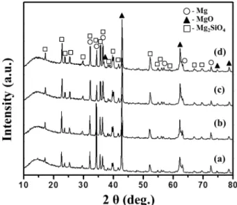
Fig. 1 shows XRD patterns of oxide layers obtained through PEO treatment with various electrolytic solutions.
Oxide layers were formed by the thermo-chemical re- action of numerous plasma discharges occurring over the surfaces of AZ91 substrates immersed in electrolytic so- lution. As shown in Fig. 1, all oxide layers mainly exhibited diffraction patterns assigned to MgO (JCPDS no.: 87-0653), Mg
2SiO
4(JCPDS no.: 87-2044), and Mg substrate. The surface of Mg alloy could be oxidized to MgO by PEO treatment. Mg
2SiO
4phase was obtained due to the reaction between Mg and SiO
32−component of the electrolyte at the surface. No peaks associated with MgF
2caused by KF were detected in the XRD patterns.
It can be inferred that there was little MgF
2in this layer under our experimental conditions. By using 3 g/L of KF for the electrolytic solution instead of 3 g/L of KOH, the XRD peak of the Mg phase decreased whereas those of MgO and Mg
2SiO
4phases increased. Owing to the thick- ness of the oxides, it can be inferred that the X-ray penetration depth in the oxide layer formed from the electrolytic solution with KF was smaller than that of the oxide layer formed from the electrolytic solution without KF. Further, the intensities of the Mg
2SiO
4and MgO phases increased with increasing concentration of KF in the electrolytic solution.
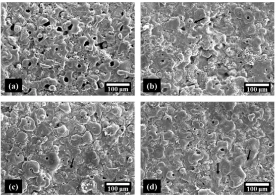
Fig. 2 illustrates the surface morphologies of oxide layers obtained through PEO treatment on AZ91 Mg alloy for 30 min in various electrolytic solutions. The entire oxide layer surfaces presented solidification structures with numerous micro-pores and melting areas(pancakes).
Fig. 1. XRD patterns of oxide layers formed in electrolyte (a) without KF (Process 1), (b) with 3 g/L KF (Process 2), (c) with 4 g/
L KF (Process 3), and (d) with 5 g/L KF (Process 4).
Table 1. Electrolyte compositions for PEO treatment.
Na
2SiO
3(g/L)
KOH (g/L)
KF
(g/L) pH Ec
(mS/cm)
Process 1 8 3 - 11.86 12.39
Process 2 8 - 3 10.82 14.98
Process 3 8 - 4 10.82 15.90
Process 4 8 - 5 10.79 16.78
In addition, some micro-cracks(see the black arrows in Fig. 2) appeared on the surfaces of oxide layers due to the thermal stress between cooled electrolytic solution
and melted oxide in the plasma discharge. The surfaces of the oxide layers treated with 3 g/L KOH exhibited roughness due to narrow melting area and large pore Fig. 3. SEM images of the cross-section of the central parts of oxide layers formed in electrolyte (a) without KF (Process 1), (b) with 3 g/L KF (Process 2), (c) with 4 g/L KF (Process 3), and (d) with 5 g/L KF (Process 4).
Fig. 2. SEM images representing the surface morphologies of oxide layers formed in electrolyte (a) without KF (Process 1), (b) with 3 g/
L KF (Process 2), (c) with 4 g/L KF (Process 3), and (d) with 5 g/L KF (Process 4).
498 Duck-Hyun Song, Dae-Young Lim, Vladimir Fedorov and Jeong-Hwan Song
size, as shown in Fig. 2(a). The pores in the oxide layer were not homogeneous either in dimension or distri- bution. However, using KF in the electrolyte led to obvious change in the surface morphology of the oxide layer. The surfaces of the oxide layers showed that the melting area increased and pore sizes decreased, as shown in Fig. 2(b-d). The addition of KF increased the electrolyte conductivity and reduced the breakdown voltage and working voltage. Therefore, the applied working voltage for the electrolytic solution with KF caused a fine spark discharge, and the number of the spark discharges in- creased on the sample surface. As a result, the oxide layers formed with increasing amount of KF became smoother owing to the disappearance of erupted solidifi- cation particles. The porosity and the pore size also decreased because of the accumulation of the oxide in the discharge channels. The surface morphology of oxide layer obtained on Mg alloy by PEO treatment was strongly dependent on the KF electrolyte.
SEM images of the cross-section of the central parts of the oxide layers obtained by PEO treatment using different electrolytic solutions are presented in Fig. 3. All of the oxide layers indicated two types of layer, a dense layer in contact with the Mg substrate and a porous layer at the surface. Plasma discharge channels and pores were de-
tected in the oxide layers. There was good adhesion between the oxide layers and the Mg substrates. The thickness of oxide layer treated in 3 g/L KOH electrolytic solution was observed to be ~50 μm. The thickness of oxide layer increased to approximately 70 μm when the electrolytic solution used 3 g/L KF instead of KOH.
Moreover, the thickness of oxide layer increased with in- creasing concentration of KF. When treated in electrolytic solution with 5 g/L KF, the thickness of oxide layer reached ~110 μm.
The elemental distribution along the thickness of the oxide layer formed from Process 2 was analyzed by EDS line scanning, as shown in Fig. 4. The existence of Mg, O, and Si in the oxide layer was attributed to the formation of MgO and Mg
2SiO
4. Besides, K and F were not detected throughout the depth of the oxide layer. As compared to the XRD results, there is agreement regarding the existence of the F element in the oxide layers.
The thicknesses of the oxide layer at the central and
edge parts of the sample obtained through PEO treatment
for 30 min in various electrolytic solutions are shown in
Fig. 5. Unfortunately, the oxide layers obtained through
PEO treatment using the base electrolytic solutions with
KOH and Na
2SiO
3show more than 2 times difference in
thickness between the edge and center. With the electrical
Fig. 4. SEM image of the cross-section and the corresponding EDS line scan along the white line of the oxide layer obtained by Process 2.
current applied to the samples, it can be inferred that the deviation of the thickness was caused by the electrical energy accumulated towards the edges of the sample. The oxide layer formed in KOH electrolytic solution without KF exhibited wide disparity in average thickness 95 μm at the edge and 45 μm at the center. The difference in thickness at the center and edge was 49.5 %. However, the thickness of oxide layer formed in the electrolytic solution with KF increased and the disparity in thickness between the central and edge parts decreased. At the concentration of 5 g/L KF, the average thickness of oxide layer was ~125 μm at the edge and 108 μm at the center.
The difference in thickness at the center and edge was 13.6 %. It was noticed that the thicknesses of oxide layers treated in electrolytic solutions with KF were thicker
than those without KF. The thickness of oxide layer increased gradually with increase in concentration of KF.
KF could therefore be used as an additive to increase the formation velocity of the oxides, as well as to enhance the electrical conductivity in the electrolytic solution con- taining KF for the PEO process.
KF-based alkaline electrolyte systems offer great oppor- tunities for potential application in the PEO treatment of Mg alloys because KF is introduced as an additive to enhance the electrical conductivity of electrolytes(Table 1). It is evident that the PEO oxide layers formed from electrolytic solutions with KF were similar in thickness at the center and edges of specimens. The reason is that there could be a fast moving electrolyte component such as OH
−or SiO
32−towards the anode sample in the pre- sence of F
−ions.
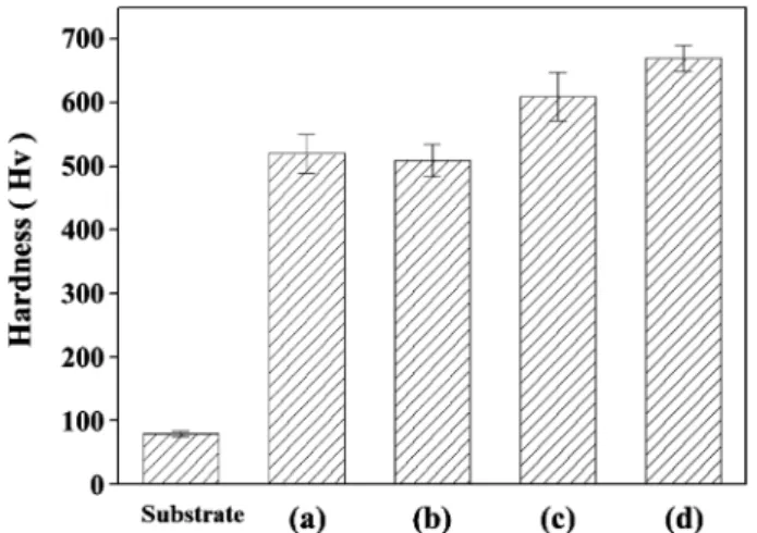
Fig. 6 shows the micro-hardnesses of oxide layers obtained through PEO treatment in various electrolytic solutions. The micro-hardness of the Mg alloy substrate is also presented for comparison. The micro-hardness of the oxide layers is more than 5 to 7 times higher than that of the Mg substrate. Furthermore, the micro-hardness of the oxide layers formed from the electrolytic solution with KF was higher than that of the oxide layers formed from the electrolytic solution without KF. The micro- hardness of the oxide layer increased with increasing amount of KF in the electrolytic solution. This can be attributed to the fact that the porosity of the oxide layer formed from the electrolytic solution with KF decreased owing to the fine spark discharge and the number of spark discharges on the sample surface increased. These oxide layers therefore have a denser surface and a more compact structure. In addition, the ratios of the different structured phases of the oxide layers consisting of MgO and forsterite Mg
2SiO
4from the XRD intensities might also partly account for the higher micro-hardness. Mg
2SiO
4has a relatively greater hardness than MgO.
12)Therefore, the micro-hardness increased with increased amount of KF in electrolytic solution.
4. Conclusions
Oxide layers were formed on AZ91 Mg alloy by the PEO process. The influence of KF electrolytic solution on the oxide layers was investigated. Using KF instead of KOH in the Na
2SiO
3electrolytic solution did not change the nature of the oxide layer such as MgO and Mg
2SiO
4, but considerably decreased the porosity and pore size. When using KF for the electrolytic solution, all oxide layers exhibited almost identical morphology such as solidification particles and melted oxides with pancake shape. It is shown that the addition of KF into the basis electrolyte for the PEO process on Mg alloys resulted in Fig. 5. Thicknesses of central and edge parts of the oxide layers
formed in electrolyte (a) without KF (Process 1), (b) with 3 g/L KF (Process 2), (c) with 4 g/L KF (Process 3), and (d) with 5 g/L KF (Process 4).
Fig. 6. Micro-hardness of the Mg substrate and the oxide layers
formed in electrolyte (a) without KF (Process 1), (b) with 3 g/L KF
(Process 2), (c) with 4 g/L KF (Process 3), and (d) with 5 g/L KF
(Process 4).
500 Duck-Hyun Song, Dae-Young Lim, Vladimir Fedorov and Jeong-Hwan Song
fabricating an oxide layer with low porosity, small pore size, and low surface roughness. The oxide layers formed in the electrolytic solution with KF had higher surface hardnesses. The uniform thickness of the oxide layer was strongly dependent on the electrolytic solution with KF, which suggests that the composition of electrolytic solu- tion is one of the key factors controlling the uniform thickness of the oxide layer.
Acknowledgment
This work was supported by a research grant from PaiChai University in 2017(No. 2017A0016).
References
1. E. Aghion, B. Bronfin and D. Eliezer, J. Mater. Process.
Technol., 117, 381 (2001).
2. H. Friedrich and S. Schumann, J. Mater. Process.
Technol., 117, 276 (2001).
3. B. L. Mordike and T. Ebert, Mater. Sci. Eng. A, 302, 37
(2001).
4. I. M. Baghni, Y. S. Wu, J. Q. Li, C. W. Du and W.
Zhang, Trans. Nonferr. Met. Soc. China, 13, 1253 (2003).
5. G. H. Wu, M. Xie, C. Q. Zhai, X. Q. Zeng, Y. P. Zhu and W. J. Ding, Trans. Nonferr. Met. Soc. China, 13, 1260 (2003).
6. H. P. Duan, C. W. Yan and F. H. Wang, Electrochim.
Acta, 52, 3785 (2007).
7. M. Zhao, S. Wu, P. An, Y. Fukuda and H. Nakae, J.
Alloys Compd., 427, 310 (2007).
8. A. L. Yerokhin, X. Nie, A. Leyland, A. Matthews and S.
J. Dowey, Surf. Coat. Technol., 122, 73 (1999).
9. J. Linag, B. Guo, J. Tian, H. Liu, J. Zhou, W. Liu and T. Xu, J. Surf. Coat. Technol., 199, 121 (2005).
10. O. Khaselev, D. Weiss and J. Yahalom, Corros. Sci., 43, 1295 (2001).
11. Y. G. Ko, S. Namgung and D. H. Shin, Surf. Coat.
Technol., 205, 2525 (2010).
12. J. Liang, L. Hu and J. Hao, Appl. Surf. Sci., 253, 4490 (2007).