한국표면공학회지 J. Korean Inst. Surf. Eng.
Vol. 50, No. 6, 2017.
https://doi.org/10.5695/JKISE.2017.50.6.432
<연구논문>
ISSN 1225-8024(Print) ISSN 2288-8403(Online)
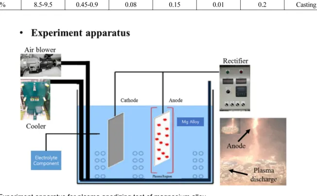
Fabrication of Plasma Electrolytic Oxidation Coatings on Magnesium AZ91D Casting Alloys
Sung-Hyung Lee
a,b,*, Hitoshi Yashiro
b, and Song-Zhu Kure-Chu
ca
GEO Nation Co. Ltd., Tokyo, Japan
b
Department of Chemistry and Bioengineering, Iwate University, Morioka, Iwate, Japan
c