• 검색 결과가 없습니다.

Characteristics of Oxide Layers Formed on Al2021 Alloys by Plasma Electrolytic Oxidation in Aluminate Fluorosilicate Electrolyte

N/A
N/A
Protected

Academic year: 2021

Share "Characteristics of Oxide Layers Formed on Al2021 Alloys by Plasma Electrolytic Oxidation in Aluminate Fluorosilicate Electrolyte"

Copied!
4
0
0

로드 중.... (전체 텍스트 보기)

전체 글

(1)

308

한국표면공학회지 J. Kor. Inst. Surf. Eng.

Vol. 41, No. 6, 2008.

<연구논문>

Characteristics of Oxide Layers Formed on Al2021 Alloys by Plasma Electrolytic Oxidation in Aluminate Fluorosilicate Electrolyte

Kai Wang

a

, Bon Heun Koo

a*

, Chan Gyu Lee

a

, Young Joo Kim

a

, Sunghun Lee

b

, Eungsun Byon

b

a

School of Nano & Advanced Materials Engineering, Changwon National University, Changwon 641-773, Korea

b

Surface Technology Research Center, Korea Institute of Materials Science, Changwon 641-010, Korea

(Received November 17, 2008 ; revised December 16, 2008 ; accepted December 30, 2008)

Abstract

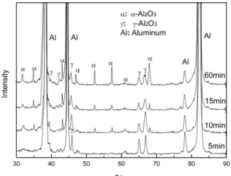
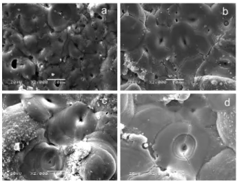
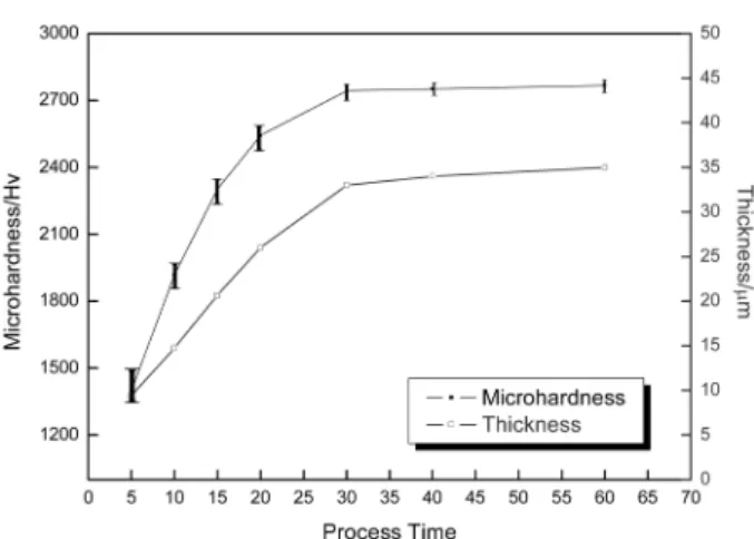
Oxide layers were prepared on Al2021 alloys substrate under a hybrid voltage of AC 200 V (60 Hz) combined with DC 260 V value at room temperature within 5~60 min by plasma electrolytic oxidation (PEO). An optimized aluminate-fluorosilicate solution was used as the electrolytes. The surface morphology, thickness and composition of layers on Al2021 alloys at different reaction times were studied. The results showed that it is possible to generate oxide layers of good properties on Al2021 alloys in aluminate-fluorosilicate electrolytes. Analysis show that the double-layer structure oxide layers consist of different states such as α-Al

2

O

3

and γ-Al

2

O

3

. For short treatment times, the formation process of oxide layers follows a linear kinetics, while for longer times the formation process slows down and becomes a steady stage. During the PEO processes, the average size of the discharge channels increased gradually as the PEO treatment time increased.

Keywords: Plasma electrolytic oxidation, Al2021 Alloy, Aluminate fluorosilicate electrolyte, Oxide layer

1. Introduction

High strength aluminum alloys are widely used in automotive and aircraft industries, which allow reducing significantly the weight of the engineering constructions. In these fields, very often the main requirements for the components include high fatigue, corrosion and wear resistance. The first requirement is achieved usually by a proper material selection.

For example, 2021 is an aluminum alloy, with copper and magnesium as the alloying elements, which is used in applications requiring high strength to weight ratio, as well as good fatigue resistance. Due to poor corrosion resistance, it is often clad with zinc or silver for protection, although this will reduce the fatigue strength

1)

. Traditional anodizing process is another classical approach to increase the tribological properties of aluminum alloys. The process running at low temperature allows formation of a thick and

strongly adherent oxide layer with high hardness

2)

. However, the coating brittleness and the cracks induced during the anodizing process also will reduce the fatigue strength of the hard-anodized components

3)

.

The novel electrochemical surface treatment process, plasma electrolytic oxidation (PEO), has been proved an effective surface protection technique to produce oxide layers on Al alloys with high tribological properties. It is reported

4,5)

that the PEO layer may cause no more than 10% reduction in fatigue limit of magnesium and aluminum alloys, which is substantially lower than the effect of anodizing. One of the most important factors affecting the fatigue strength of PEO layers is the internal residual stress. It is recognized that the compressive residual stresses retard the fatigue crack initiation in the layer and therefore the fatigue life of the coated components increases

6)

. Further researches showed that the PEO oxide layers offered attractive combination of wear resistance, corrosion resistance, mechanical strength, interfacial

*

Corresponding author. E - mail : [email protected]

(2)

Kai Wang 외/한국표면공학회 41 (2008) 308-311 309

adhesion and thermal property

7-9)

.

According to previous researches

4)

, aluminate solution has been proved that it is able to form smooth oxide layers on Al alloys as no introduction of impurities. Besides, the addition of fluorite and silicate elements can also effectively enhance the property of the oxide layers

10)

. In the present work, the PEO processes were carried out to produce oxide layers on Al2021 alloy in alkaline aluminate fluoro- silicate electrolytes. An optimized hybrid voltage of 200 V AC amplitude combined with 260 V DC value was applied from the power supply. The surface morphology, microstructures, elemental distribution and microhardness of oxide layers were investigated.

2. Experimental

Al2021 alloy (Cu, 5.8-6.8 wt.%; Mg, 1.2-1.8 wt.%;

Si, 0.5 wt.%; Fe, 0.5 wt.%, Zn, 0.1 wt.%; Mn, 0.2- 0.4 wt.%; Ti, 0.15 wt.% and Al, balance) with dimension of D 30 mm × H 16 mm and surface roughness of Ra 0.1 μ m were fabricated. Prior to PEO treatment, samples were pretreated (degreased and ultrasonically cleaned in the acetone medium and thoroughly dried), and then immersed in electrolyte for PEO treatment. During the treatment, the PEO process was carried out at the room temperature for 5~60 min in a 2-litre water-cooled stainless steel tank, which also served as a counter electrode, and the metallic samples immersed in the electrolyte served as an anode. The electrolytes contain Na

2

AlO

2

, Na

2

SiF

6

and NaOH of 8 g/ l , 0.5 g/ l and 2 g/ l separately.

According to previous researches, a hybrid voltage of 200 V AC (60-Hz) with 260 V DC was applied from the PEO power supply. After the treatment, the specimens were thoroughly rinsed in running demineralized water and dried with compressed air.

The AC amplitude was slowly increased to 200 V to maintain the current density at 3~4 dA/cm

2

throughout the experimentation, afterwards the DC value was increased gradually till 260 V so as to maintain the reset current density even as the layer thickness gradually increased. The plasmas initiated to discharge throughout the surface at DC 140 V based on AC 200 V. During the PEO process, plenty amount of water vapor was generated by the exothermal PEO reaction.

The phases of the oxide layers were investigated with Philips-X’Pert system X-ray diffractometer (XRD) (Cu K

α

radiation) and the scans were performed with 0.02

o

step size in the 2 θ range of 30-90

o

. The micro-

structures of surfaces and cross-sectional morphologies of treated samples were examined by a JSM 5610 scanning electron microscopy (SEM). The micro- hardness of the oxide layers at each 10 different places were measured by VLPAK2000 Mitutoyo Hardness Test Machine using 0.1 N loading energy in 30s dwell time, and then the average microhardness was calculated.

3. Results and Discussion

The XRD patterns of PEO layers prepared in 5, 10, 15 and 60 min separately are presented in Fig. 1.

Strong diffraction peaks of the Al substrate were detected because the layers are so thin that X-rays could penetrate the layers easily. From Fig. 1, it is concluded that typical phase composition of PEO layers represented by α -Al

2

O

3

and γ -Al

2

O

3

are the main phases. The γ -Al

2

O

3

phase dominated the layers during the short time treatment. With the increasing treatment time, γ -Al

2

O

3

phase gradually transformed into α -Al

2

O

3

phase. It is well known that α -Al

2

O

3

is a stable alumina phase, which has a trigonal structure with a high melting point of 2050

o

C. Moreover, γ - Al

2

O

3

is a meta-stable phase, which can transform into α -Al

2

O

3

phase by heating up to the temperature interval between 800 and 1200

o

C

11,12)

.

Fig. 2 illustrates the surface features of the PEO- treated samples in different reaction times. It is clearly indicated that the presence of discharge channels in all electrolytes appeared as the same dark circular spots, with pancake like microstructures, which distributed all over the surface of the layers.

Because of the existence of the brittle phase of α - Al

2

O

3

, surface defects of cracks unavoidable appeared

Fig. 1. XRD patterns of the oxide layers prepared in 5,

10, 15 and 60 min.

(3)

310 Kai Wang 외/한국표면공학회 41 (2008) 308-311

on the layer surfaces. From the figures, it is concluded that the average size of the discharged channels increase gradually as the treatment time increased.

Besides, there were some porous phases on the layer surfaces. Sodium fluorosilicate was easily decomposed at high temperatures in the discharging channels to release silicon and fluorite ions. Silicon was prove to be an immigrate element

13)

, which would combine with aluminum ions to form the Al-Si-O phase.

Afterwards, the Al-Si-O phase would then be ejected out of the discharging channels and pushed around the discharging channels, finally cooled down and solidified as the porous phase around the channels.

The cross-sectional SEM micrographs of the layers processed in 5, 15, 30 and 60 min are shown in Fig.

3. Fig. 4 reports the measurements of the average

layer thickness as a function of the treatment time.

From these figures, it is clear that the average layer thickness increases linearly with the increase of the reaction time at the initial state, and then the growth rate slowed down, and finally it leveled off after 30 min reaction. Such increasing growth kinetics of the formation of the oxide layers was studied by other researchers

14,15)

. According to these researchers, the oxide layers growth results from molten aluminum that was oxidized when flowing outwards through the discharging channels. By this way, alumina was formed and transformed to form different phases, and contributed to the growth of the layers when being ejected from the channels and rapidly quenched at the interface between electrolyte and substrates. In the initial linear growth stage, the transformation of

γ -Al

2

O

3

to α -Al

2

O

3

was the main reason that led the growth of the outer oxide layer. The discharge phenomenon was shown to be violet, tiny and fast moving by visual observation. When the outer oxide layer grew thick enough, then the alumina phase transformation slowed down, and the γ -Al

2

O

3

phase gradually increase and form the inner layer. Finally, when both the outer and inner oxide layer grew thick, they were hard to be broken down. So the growth rate decreased rapidly, and finally levelled off. In this stage, the discharge phenomenon became yellow, larger and slower moving. Above all, the double-layer structure oxide layer finally formed, consisted of hard α -Al

2

O

3

phase distributed upon γ - Al

2

O

3

phase, which could behavior as a buffer zone and resulted in good shock absorption ability.

The oxide layers were hard to break when they Fig. 2. SEM surface morphologies of PEO treated

samples prepared in different times of (a) 5 min, (b) 15 min, (c) 30 min, (d) 60 min.

Fig. 3. Cross-sectional SEM micrographs of the oxide layers prepared in different times of (a) 5 min, (b) 10 min,

(c) 15 min, (d) 30 min, (e) 60 min.

(4)

Kai Wang 외/한국표면공학회 41 (2008) 308-311 311

became thicker with the increased treatment time. So, at the last stage of the PEO process, only few weak area continue to discharge, which could effectively heal the defects such as crack and bubbles generated in the initial stage.

Fig. 4 reports the measurements of the outer layer microhardness and the total layer thickness as a function of the treatment time. The outer layer microhardness presents a similar growth trend as the total layer thickness. It is expected that the proportion of α -Al

2

O

3

phase gradually increased with the reaction time. Such a phase gradient is responsible for the observed microhardness variation accounted with the reaction time. While the inner layer microhardness is about 400 Hv as it is consisted of soft γ -Al

2

O

3

phase.

4. Conclusions

The PEO processes were carried out in alkaline aluminate fluorosilicate electrolytes on Al2021 alloys substrate within 5~60 min under a hybrid voltage.

The PEO oxide layers present smooth surfaces, with pancake structures surrounded by small amounts of Al-Si-O porous phases. During the PEO process, the size of the discharge channels increase gradually with the increase of the treatment time. The oxide layers mainly consisted of γ -Al

2

O

3

and α -Al

2

O

3

. The transformation of γ -Al

2

O

3

into α -Al

2

O

3

results in the linear growth of the oxide layer in the initial stage, and then the growth of γ -Al

2

O

3

took the place of transformation to accelerate the growth of the oxide

layer, finally the growth rate leveled off and a double-layer structure oxide layer formed. The amounts of alumina phases were responsible for different oxide layer thickness and the hardness variation.

Acknowledgement

This work was supported by the Korea Research Foundation Grant (KRF-2006-005-J02703).

References

1. D. V. Dunford, P. G. Partridge, J. Mater. Sci., 22 (1987) 1790.

2. B. Meyers, S. Lynn, ASM Handbook, Surface Engineering. Vol. 5, ASM International Materials Park, OH, USA, (1994) 925.

3. V. Moutarlier, M. P. Gigandet, J. Pagetti, L. Ricq, Surf. Coat. Tech., 173 (2003) 87.

4. A. L. Yerokhin, A. Shatrov, V. Samsonov, P. Shashkov, A. Leyland, A. Matthews, Surf. Coat. Tech., 182 (2004) 78.

5. B. Lonyuk, I. Apachitei and J. Duszczyk, Surf.

Coat. Tech., 201 (2007) 8688.

6. G. Dieter, D. Bacon, Mechanical Metallurgy, McGraw-Hill Book Company, New York, USA (1988) 378.

7. W. Xue, C. Wang, Z. Deng, R. Chen, Y. Lai, T.

Zhang, J. Phys.: Condens. Matter., 14 (2002) 10947.

8. J. A. Curran, T.W. Clyne, Surf. Coat. Tech., 199 (2005) 168.

9. Y. Wang, T. Lei, B. Jiang, L. Guo, Appl. Surf.

Sci., 233 (2004) 258.

10. Y. K. Wang, H. Y. Zheng, B. S. Li, G. R. Han, L. F. Yuan, Electro. Fin., 22 (2003) 8.

11. T. B. Wei, F. Y. Yan, J. Tian, J. Alloys Comp., 389 (2005) 169.

12. H. H. Wu, Z. S. Jin, B. Y. Long, F. R. Yu, X. Y.

Lu, Chin. Phys. Lett., 20 (2003) 1815.

13. G. H. Lv, W. C. Gu, H. Chen, W. R. Feng, M. L.

Khosa, L. Li, E. W. Niu, G. L. Zhang, S. Z. Yang, App. Surf. Sci., 253 (2006) 2947.

14. W. Xue, Z. Deng, R. Chen, T. Zhang, Thin Solid Films, 372 (2000) 114.

15. W. C. Gu, G. H. Lv, H. Chen, G. L. Chen, W. R.

Feng, S. Z. Yang, Mater. Sci. Eng. A, 447 (2007) 158.

Fig. 4. Microhardness and thickness of the oxide layers

prepared in 5~60 min.

수치

Fig. 2 illustrates the surface features of the PEO- PEO-treated samples in different reaction times
Fig. 3. Cross-sectional SEM micrographs of the oxide layers prepared in different times of (a) 5 min, (b) 10 min, (c) 15 min, (d) 30 min, (e) 60 min.
Fig. 4 reports the measurements of the outer layer microhardness and the total layer thickness as a function of the treatment time

참조

관련 문서

Surface characteristics of hydroxyapatite coated Ti-40Ta-xNb alloys by plasma electrolytic oxidation and sputtering

pottery, tableware, cookware, building materials, aerospace materials, to nuclear materials (e.g., UO 2 pellets, waste forms, etc.)... A’ a’ B’ b’ C’

Decomposition (MOD) process, and then the zinc oxide nanorods on ZnO seed layer were grown by hydrothermal process from 0.3 M at pH 7, 80 ℃ , 1 h. Single phase zinc oxide

photovoltaics, plasma remediation of greenhouse and toxic gases, and plasma destruction of hazardous wastes..  Low-temperature plasma production of nanoscale

Improvement of the Performance and Stability of Oxide Semiconductor Thin-Film Transistors Using Double-Stacked Active Layers.. Metal oxide semiconductor

In this study, we investigated the surface characteristics of hydroxyapatite film on the micro-pore structured Ti-35Ta-xNb alloys by

Among the various methods, plasma electrolytic oxidation (PEO) is a method for surface processing in which a biocompatible oxide film is formed using a number of ions..

In Chapter 3, I described growth results of tungsten carbide buffer layers on Si substrate and analyzed those physical properties.. In Chapter 4, GaN growth