≪연구논문≫ Journal of the Korean Magnetics Society 29(5), 171-176 (2019) https://doi.org/10.4283/JKMS.2019.29.5.171
− 171 −
Construction of 3-axis Flux-gate Magnetometer That Measure Total Magnetic Field
Derac Son*
Department of Photonics and Sensors Engineering, Hannam University, Daejeon 34430, Korea (Received 17 September 2019, Received in final form 20 October 2019, Accepted 21 October 2019)
Magnetic field measurement under vibration and rotation condition of the magnetometer, total field measuring magnetometers have been used, because orthogonality error and scale factor differene of the 3-axis magnetometer can not measure total magnetic field with high precission. In this study, we developed total magnetic field sensor by orthogonality correction for the 3-axis flux-gate magnetometer. To correct orthogonality and scale factor, 24 bit 3-channel simultaneous digitizing ADC and DSP were used. To demonstrate the performance of the developed magnetometer under condition of vibration, the magnetometer was installed on dron and measured magnetic anormality of passenger cars. We can measure total magnetic field with resolution of 1 nT for the developed orthogonality corrected 3-axis flux-gate magnetometer.
Keywords : magnetometer, total magnetic field, flux-gate magnetometer, orthogonality correction, magnetic field measurement
자기장크기 측정이 가능한 3-축 Flux-gate 마그네토미터 제작
손대락*
한남대학교 광센서공학과, 대전시 대덕구 한남로 70, 34430
(2019년 9월 17일 받음, 2019년 10월 20일 최종수정본 받음, 2019년 10월 21일 게재확정)
Total magnetic field를 측정하는 magnetometer는 진동이나 회전이 있는 측정환경에서도 측정이 가능하나, 일반적인 3-축의 magnetometer의 경우 축사이의 각도가 직각에서 1o 정도의 오차를 가지고 있다. 따라서 total magnetic field를 측정하는데 많은 오차를 가져왔다. 본 연구에서는 3-축 사이의 각도를 측정하고 수학적으로 이를 보정하여 total magnetic field의 측정이 가능한 3-축 flux-gate magnetometer를 제작하였다. 개발된 3-축의 flux-gate magnetometer는 각축의 정밀도 차이가 0.01% 이하 되게 제 작을 하였고, 자기장의 크기를 계산하기위하여 3-채널 자기장 신호를 24 bit 으로 동시에 측정이 가능한 ADC를 사용하였으며, DSP를 사용 직각도를 보정하여 직각도를 0.1o 이하 되게 보정을 한 자기장 값을 출력할 수 있게 하였다. 개발된 magnetometer 의 성능을 검증하기 위하여 magnetometer를 드론에 장착하여 측정한 결과 드론의 진동에도 불구하고 total magnetic field를 1 nT 의 정밀도로 측정할 수 있었다.
주제어 : 마그네토미터, 자기장크기 측정, 플럭스게이트 마그네토미터, 직각도 보정, 자기장측정
I. 서 론
일반적으로 자기장을 측정하는 방법은 1-축의 자기장을 측 정하는 방법과 자기장의 크기(total magnetic field 또는 magnetic field magnitude)를 측정하는 방법이 있다. 1-축의 자기장을 측정하는 방법으로는 flux-gate magnetometer, Hall sensor, AMR 센서, GMR 센서, GMI 센서 및 SQUID 등 이 있다[1]. 자기장의 크기를 측정하는 센서로는 NMR
Magnetometer, Proton precession magnetometer, Optical pumping He/Cs vapour magnetometer로 양자현상을 이용 하고 있다[2]. 이 경우 자기장으로 핵이나 전자의 spin을 polarize시킨 후 측정을 하기 때문에 피 측정 자기장과 spin 을 polarize한 방향이 같아지게 되면 센서의 감도가 낮아지는 단점을 가지고 있다.
1-축 자기장센서를 활용하여 3-축의 자기장센서를 구축하고 이들 3-축의 자기장센서를 사용하여 자기장의 크기 및 3-축 자기장 성분을 모두 측정하려면 다음과 같은 문제점을 해결 하여야 한다.
1. 센서 각 축간의 직교성(Orthogonality)
© The Korean Magnetics Society. All rights reserved.
*Corresponding author: Tel: +82-42-629-7512, Fax: +82-42-629-8313, e-mail: [email protected]
2. 각 축 scale factor의 동일성 3. 3축의 자기장성분 동시 측정
만약 3가지의 문제가 해결이 되면 자기장의 성분과 크기를 동시에 측정할 수가 있어서 양자현상을 이용하여 자기장 크 기를 측정하는 센서보다 큰 장점을 가질 수 있다. 왜냐하면 대부분의 양자현상을 이용하는 magnetometer는 크기 및 전력 소비가 크고, 세슘의 전자(electron)인 경우 Lamour precission frequency가 3.498572 Hz/nT로 동특성이 우수하지 않기 때문 에 특히 드론 등의 무인기에 장착을 하는데 문제가 된다[3].
본 연구에서는 선형도가 우수한 feedback형 3-축 flux-gate magnetometer의 직각도를 보정하여 자기장의 크기를 측정하 는 magnetometer에 관하여 연구를 하였다.
II. 3-축 직각도 보정이론
Fig. 1과 같이 2-축의 센서가 서로 직각이 아니고 직각에서 각도가 δ 만큼 다를 경우 피 측정 지구자기장 BE가 x-축으로 부터 θ 각도에 있을 때 x'-, y-축으로부터 측정한 자기장 B'E
는 δ << 1o일 경우 다음과 같다.
B'E≈ BE(1 +δsinθcosθ) (1)
측정편차 ΔB'E= (B'E− BE) =BEδsinθcosθ에 대하여 지구자 기장 BE가 50 μT 일 때 계산한 결과가 Fig. 2와 같다. θ가 45에서 편차가 가장 크게 나타났으며, 일반적으로 flux-gate magnetometer를 제작하면 δ ≈ 1o(= 0.0174rad) 정도 되기 때 문에 최대 측정편차는 0.44 μT 정도 된다. 따라서 2-축의 magnetometer를 회전시키면 자기장 크기 50 μT의 측정값편차 가 최대 0.43 μT의 변화를 가져오는 것을 의미하며, 이 경우 0.1μT 정도의 자기장을 발생시키는 표적의 자기탐지는 매우 어려워진다.
따라서 각도 오차에 의한 total field 측정 오차를 10−3 % 정도 가지려면 직각도 오차가 0.1o되어야 함을 의미하고 이
는 기구적으로 센서의 제작이 매우 어렵다. 따라서 3-축 flux-gate magnetometer에서 이 문제를 개선하려면, 각축의 각도 오차를 정밀하게 측정하여 이를 수학적으로 보정하는 방 법을 생각해야 한다.
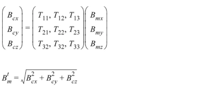
3-축의 flux-gate magnetometer를 제작하면 일반적으로 축 사이의 각도가 직각에서 1o정도 벗어난다. 이 경우 각축에서 측정된 자기장 값 Bmx, Bmy, Bmz로부터 자기장의 크기를 계산 하면 앞에서 언급한 봐와 같이 실제 자기장 크기 Bmt와 다르 며, 다음 식(2)과 같이 다르게 된다.
(2) 만약에 직각도가 우수한 자기장 발생장치를 이용하여 축사 이의 각도를 정밀하게 측정을 하고, 이를 다음의 좌표변환 행 렬식(3)을 이용하여 좌표축 방향의 자기장성분으로 구할 수 있으면, 자기장 발생장치의 좌표에서 3-축의 flux-gate magnetometer 자기장 성분으로부터 직각도가 보정이 된 자기 장 측정 값 Bcx, Bcy, Bcmz를 구할 수 있고 이로 부터 자기장 의 크기를 계산하면 실제 자기장 크기 Bmt가 되어 식(4)와 같이 되고 축 사이의 각도편차에 의한 측정 자기장 편차를 최소화 할 수 있다. 이렇게 하여 자기장의 크기 Bmt를 측정 하게 되면 자력계의 자세에 무관하게 자기장의 크기를 측정 할 수 있게 되어 scalar magnetometer의 기능을 3-축의 flux- gate magnetometer에서 구현을 할 수 있게 된다. 따라서 3-축 의 flux-gate magnetometer도 MAD(Magnetic Abnormally Detection)등에 활용될 수 있게 되며, 3-축의 flux-gate magnetometer의 장점인 저전력의 소형이 가능하여지기 때문 에 최근 많이 사용하려는 UUV, USV, UAV 등에 적용할 수 있음을 알 수 있다[5].
Bmt ≠ Bmx2 + Bmy2 + Bmz2
Fig. 1. (Color online) Magnetic field measurement using 2-axis magnetometer which is not orthogonal and angle deviation is δ.
Fig. 2. (Color online) Total magnetic field measurement errors using 2-axis magnetometer which is not orthogonal and different angle deviation under earth magnetic field of 50μT.
(3)
(4)
III. 3-축 Flux-gate Magnetometer 제작 Flux-gate magnetometer는 2차 세계대전을 전후로 개발된 magnetometer로 아직도 많은 영역에 사용되고 있다. Flux- gate magnetometer의 원리는 여러 가지가 있으나[2,6], 본 연 구에서는 코어에 유도되는 기전력의 2차 고조파성분이 피측 정 자기장에 비례하는 것을 이용하였다. 센서의 선형도를 향 상시키기 위하여 2차 고조파성분을 증폭하고 저주파대역증폭 기를 통과한 전압신호를 피드백을 시키는 방식을 본 연구에 서 택하였다[4]. 제작한 자력계의 회로도는 Fig. 3과 같다.
Oscillator는 8 bit의 MCU인 Attiny 45V를 사용하여 자화주 파수 10 kHz와 2차 고조파성분을 측정하기 위한 20 kHz의 TTL 신호를 발생시켰다. De-modulator와 LPF(Low Pass Filter)를 사용 피측정 자기장에 비례하는 전기적 신호를 2차 코일에 feed-back 시켜서 피측정 자기장과 반대 방향의 자기 장을 발생시킴으로써 magnetometer의 선형도를 0.01% 이상 얻을 수 있었다. 3-축의 아날로그 신호는 4-채널을 동시에 디
지털신호로 변환시키는 24 bit의 delta-sigma ADC (Analog to Digital Converter) AD7768-4를 사용하였다. 마그네토미터 에 사용된 코어는 Co계 비정질 리본 Metglass®2714A를 폭 이 3 mm되게 슬리팅 한 후 열처리하여 사용하였다. 24 bit의 각축 자기장 성분은 DSP를 사용하여 직각도를 보정한 후 출 력은 0.01 nT의 분해능으로 ASCII 디지털 신호로 변환하여 컴퓨터와 RS422 serial 통신을 할 수 있게 하였다. Fig. 4는 본 연구에서 제작된 플럭스 게이트 마그네토미터의 사진이다.
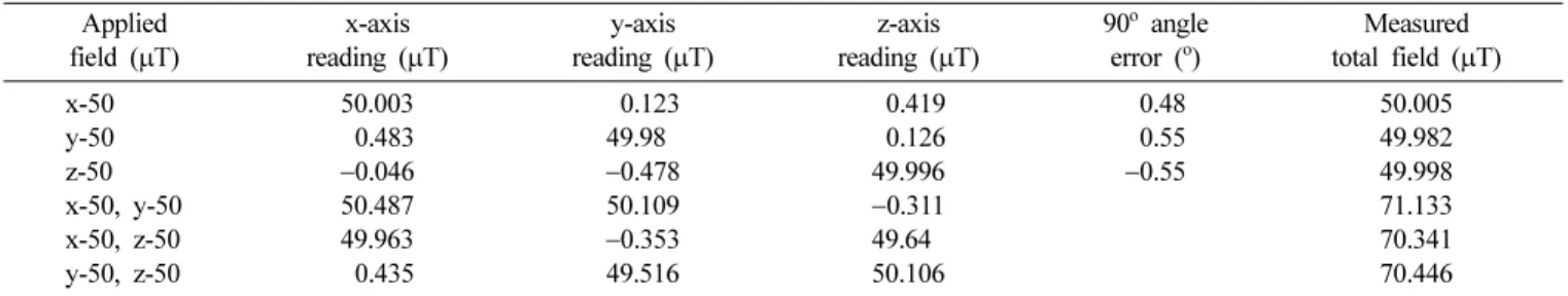
제작된 3-축 flux-gate magnetometer는 직각도 오차가 0.1o 이하인 3-축의 Helmholtz 코일을 사용하여 비자성실험에서 직각도를 측정한 결과가 Table I이다. 측정결과를 보면 직각 도가 0.5o이상 벗어나 있고, 각축에서 50 μT 자기장을 인가 Bcx
Bcy Bcz
⎝ ⎠
⎜ ⎟
⎜ ⎟
⎜ ⎟
⎜ ⎟
⎛ ⎞
=
T11, T12, T13 T21, T22, T23 T32, T32, T33
⎝ ⎠
⎜ ⎟
⎜ ⎟
⎜ ⎟
⎜ ⎟
⎛ ⎞ Bmx
Bmy Bmz
⎝ ⎠
⎜ ⎟
⎜ ⎟
⎜ ⎟
⎜ ⎟
⎛ ⎞
Bmt = Bcx2 + Bcy2 + Bcz2
Fig. 3. (Color online) Schematic diagram of the 3-axis flux-gate magnetometer which can measure 3-axis magnetic field simultaneously.
Fig. 4. (Color online) Photography of the constructed 3-axis flux-gate magnetometer; analogue PCB (above), and digital PCB (below).
하여 대각선 방향으로 70.707 μT 자기장을 인가하였을 때 측 정값은 0.4% 정도의 오차를 가졌다. Table II는 3-축의 Helmholtz 코일을 사용 3-축에 대하여 각-축 마다 자기장을 인가한 후 3-축의 자력계 성분을 모두 측정하여, 직각도 보정 행렬식(2)의 Tij를 구한 후, 이 값을 3-축 flux-gate magneto- meter의 F/W에 입력한 후에 자력계의 특성을 측정한 결과이 다. 측정결과를 보면 직각도는 Helmholtz 코일의 직각도와 0.02o이하로 수학적인 보정이 가능함을 보여주고 있으며, 직 각도 오차에 의한 자기장크기의 측정오차가 가장 큰 대각선 방향에서도 측정오차가 0.01% 이하였다.
IV. 제작된 Magnetometer의 성능 시험 제작된 3-축 flux-gate magnetometer의 성능을 확인하기 위하여 magnetometer의 자세가 일정하지 않는 조건으로, magnetometer를 드론에 장착하고 지상의 승용차에 의한 MAD(Magnetic Anormaly Detection)신호를 측정하였다. 자 력계의 측정값은 지상에서 노트북 컴퓨터로 수신을 하게 구 성하였다. Fig. 5은 측정을 하고 있는 사진이다. 측정은 승용 차의 길이 5 m를 고려하여 측정 높이는 승용차의 윗부분에서 2 m, 5 m, 8 m에서 측정을 하였다. Fig. 6는 제작된 직각도 Table I. Orthogonality error of the constructed magnetometer without orthogonality correction.
Applied field (μT)
x-axis reading (μT)
y-axis reading (μT)
z-axis reading (μT)
90o angle error (o)
Measured total field (μT)
x-50 50.003 −0.123 −0.419 −0.48 50.005
y-50 −0.483 49.980 −0.126 −0.55 49.982
z-50 −0.046 −0.478 49.996 −0.55 49.998
x-50, y-50 50.487 50.109 −0.311 71.133
x-50, z-50 49.963 −0.353 49.640 70.341
y-50, z-50 −0.435 49.516 50.106 70.446
Table II. Orthogonality error of the constructed magnetometer after orthogonality correction.
Applied field (μT)
x-axis reading (μT)
y-axis reading (μT)
z-axis reading (μT)
90o angle error (o)
Measured total field (μT)
x-50 50.003 −0.006 00.012 −0.014 50.003
y-50 −0.009 50.009 00.013 −0.015 50.009
z-50 −0.006 −0.006 50.005 −0.007 50.005
x-50, y-50 50.009 49.988 00.003 70.709
x-50, z-50 49.999 −0.014 50.000 70.710
y-50, z-50 −0.003 49.998 49.998 70.708
Fig. 5. (Color online) Photography of experiment to test MAD of passenger car using 3-axis flux-gate magnetometer.
가 보정된 3-축 자력계를 드론에 장착하여 측정한 결과이다.
측정결과를 보면 x-축, y-축, z-축의 자기장 측정 값(Fig.
6(a), (b), (c))가 드론의 진동에 의하여 6000 nT 이상 변화함 을 알 수 있다. 그러나 자기장의 크기(Fig. 6(d))는 진동의 효과가 모두 없어지고 승용차로부터 2 m, 5 m, 8 m에서 측정 된 승용차에 의한 자기장의 변화를 잘 보여주고 있다. 또한 Fig. 6(d) 내부에 확대한 그림을 보면 승용차가 없는 영역에 서 드론의 진동에 의한 자기장크기의 잡음 영향이 1 nT 정도 임을 확인 하였다. 개발된 자력계는 지하에 매설된 불발병기 (UXO)의 탐색이나, MAD 등에 활용 될 것으로 기대된다.
V. 결 론
본 연구에서는 3-축의 flux-gate magnetometer는 움직이는 자세에서도 자기장의 크기를 측정할 수 있게 하기 위하여 3- 축의 자기장 측정 값이 서로 직교(orthogonal)가 되게 보정을 할 수 있고, 3-축의 scale factor가 모두 같게 하면서 3-축의 자기장을 동시에 측정을 할 수 있게 개발을 하였다. 이를 위 하여 3-축의 자기장 신호를 디지털 신호로 변환시키기 위하
여 3-채널을 24 bit으로 동시 변환 시키는 ADC와 DSP를 사 용하였다. 개발한 magnetometer는 선형도가 0.01% 이상 되 었으며, 직각도의 보정은 직각도가 0.1도 이상인 정밀 3-축 Helmholtz 코일 시스템을 사용하였다.
제작된 3-축 센서는 자기장의 회전에서도 자기장의 크기의 변화가 0.01% 이하였으며, 성능검증을 위하여 센서를 드론에 부착하고 승용차의 자기장 분포를 측정하여 본 결과 드론의 진동에도 불구하고 표적물에 의한 자기장 크기를 1 nT의 분 해능으로 측정을 할 수 있었다.
감사의 글
본 연구는 2017년 한남대학교 교비연구비의 지원으로 이루 어졌으며 이에 감사드립니다.
References
[1] W. Goepel, J. Hesse, and J. N. Zemel, Sensors Vol. 5 Magnetic Sensors, VCH, Weinheim (1989) pp. 154~203.
[2] D. Son, Ph.D. Thesis, Universitaet der Bundeswehr Hamburg, Fig. 6. (Color online) Experimental results of MAD test using 3-axis flux-gate magnetometer; (a) x-axis output, (b) y-axis output, (c) z-axis output, and (d) total field calculated from 3-axis data.
Germany (1990).
[3] G-822/G-823 Magnetometer Manual, GEOMETRICS, INC.
ftp://geom.geometrics.com/pub/mag/Manuals/MAN822AO_
revB5.pdf.
[4] D. Son, J. Korean Magn. Soc. 22, 45 (2012).
[5] T. Bell, H.Khader, NRL/MR/6110-12-9385, Naval Research Laboratory (2012).
[6] X. Trinh, J. Jeng, C. Lu, and V. Luong, J. Magn. 24, 350 (2019).