694 https://doi.org/10.9713/kcer.2018.56.5.694
PISSN 0304-128X, EISSN 2233-9558
SnO
2Mixed Banana Peel Derived Biochar Composite for Supercapacitor Application
Indu Kaushal, Sanjeev Maken* and Ashok Kumar Sharma†
Department of Materials Science and Nanotechnology, Deenbandhu Chhotu Ram University of Science and Technology, Murthal-131 039, India
*Department of Chemistry, Deenbandhu Chhotu Ram University of Science and Technology, Murthal-131 039, India (Received 20 January 2018; Received in revised form 26 June 2018; accepted 29 June 2018)
Abstract − Novel SnO2 mixed biochar composite was prepared from banana peel developed as electrode material for supercapacitor using simple chemical co-precipitation method. The physiochemical and morphological properties of activated composite SnO2 mixed biochar were investigated with XRD, FTIR, UV-vis, FESEM and HRTEM. The com- posite accounts for outstanding electrochemical behavior such as high specific capacitance, significant rate capability and leading to good cycle retention up to 3500 cycles when used as electrode material for supercapacitors. Highly per- meable SnO2 mixed biochar derived from banana peel exhibited maximum specific capacitance of 465 F g-1 at a scan rate of 10 mV s-1 by cyclic voltammetry (CV) and 476 Fg-1 at current density of 0.15 Ag-1 by charge discharge studies significantly higher about 47% than previously reported identical work on banana peel biochar.
Key words: SnO2, Biochar, Specific capacitance, Supercapacitor, Composite
1. Introduction
The demand for energy elevates the research in developing renewable energy and cost effective materials. During last decades, supercapacitors, also known as electrochemical double layer capacitors (EDLC), have maintained a pace as energy storage materials. Superca- pacitors have numerous features like cyclic stability, easy charge/dis- charge mechanism, portable energy and power density. The electrode materials for the supercapacitor are garnering substantial research attention from materials science as well as energy storage area.
Activated carbon (AC) is commonly used as an electrode mate- rial in EDLC. However, most carbon based materials (e.g., carbon blacks, carbon nanotube, graphene, initiated carbon) [1,2] used as super capacitor electrodes result from complex chemical products, which have high cost and adversely affect the environment as well.
Unfortunately, it is not possible to recover activated carbon com- pletely and further difficulty in discarding with process sludge leads to secondary pollution [3-5].
To overcome the environmental concern and cost constraints, the waste or by-products derived from natural products can provide an alternative to the electrode material used for renewable energy storage. Generally, AC was reported to be prepared via pyrolysis of biomass feedstock, including peanut shells, banana peels, hemp, corn husk, coconut shell, citrus peel, white clover, pomelo mesocarp, and cinnamon stick [6-16]. In recent years, activated biochar carbon has earned extensive attention for supercapacitor investigation works.
Biochar is carbon-rich material synthesized by the pyrolysis of biomass which can replace activated carbon effectively as EDLC electrode materials for capacitor [6,8,17]. Biochar can be obtained from biomass as given below. In this study, biochar was obtained from banana by hydrothermal method. There are various ways for preparation of biochar: biological, chemical, thermo-chemical. Biologi- cal process needs long duration for treatment and refinement while thermo-chemical approach has advantages of short processing time and high yield [16,18].
The hydrothermal process has been employed for the conver- sion of biomass into bio-oil, biochar, or gaseous fuels. As per the literature survey, biochar prepared from the hydrothermal carbon- ization shows a substantial rise in its carbon content than the biochar synthesized by other methods. Moreover, there is also substantia- tion that the hydrothermally prepared biochar has higher energy density [19].
Considering the supercapacitor industry, the introduction of renewable biochar to prepare carbon electrode would be cost effec- tive and eco-friendly. Metal/metal oxides are another class of pseudo capacitive materials applicable for developing supercapacitor [10,13].
Biochar has a smaller surface area and less porosity than AC, but also features more surface oxygen-containing functional groups [20,21]. Transition metal oxide mixing not only enhances the elec- trochemical activity of carbon materials, but also serves as nucle- ation and anchoring sites for better dispersion and loading of pseudo capacitive materials [22,23]. In this paper a novel route for the syn- thesis of transition metal oxide-mixed carbon materials is proposed for energy storage devices using a simple, low-cost and green process.
Mixing has been molded as a dominant practice to advance the features of metal oxides [24,25]. Tin oxide (SnO2) is a conducting
†To whom correspondence should be addressed.
E-mail: [email protected]
This is an Open-Access article distributed under the terms of the Creative Com- mons Attribution Non-Commercial License (http://creativecommons.org/licenses/by- nc/3.0) which permits unrestricted non-commercial use, distribution, and reproduc- tion in any medium, provided the original work is properly cited.
material [26] that displays exceptional properties in lithium ion batteries and super capacitors. Tin oxide is also being used as a pro- moter for MoOx and RuO2 based super capacitors [27,28].
Compared to individual biochar and SnO2 mixed biochar, the as- synthesized SnO2 mixed biochar composite displays evidently enhanced specific capacitance, due to the synergetic effect between metal oxide and carbon material. Moreover, the obtainable best specific capacitance (465 F g-1 at 10 mV s-1, 476 F g-1 at 0.15A g-1) of this SnO2 mixed biochar composite is comparable to those of some biomass-derived biochar electrode material [16,23].
2. Materials and Methods
SnO2 mixed biochar composite was prepared by co-precipita- tion method [29]. A typical preparation of composite is described in the following section.
2-1. Synthesis of Biochar from Banana peel
In the first step, 20 g of unripe banana peel was purchased from the local market, Sonepat Haryana, (India) and 60 mL of deionized water was placed in a commercial Teflon-lined autoclave with a capacity of 150 mL. The autoclave was sealed tightly and subjected to a temperature of 180oC for duration of 24 h. It was allowed to cool to room temperature. The biochar was filtered, washed succes- sively with deionized water till the filtrate pH was 7, then washed with ethanol, and subsequently dried in an oven at 120oC for 24 h.
Subsequently, the biochar material was thermo-treated at 500oC for 2 h under argon flow [1].
2-2. Synthesis of SnO2 mixed Biochar Composite
Initially, 0.005 M of SnCl2. 2H2O solution was prepared in etha- nol: water (1:1 by volume). 0.1 g of as synthesized biochar was dis- persed in 100 ml of this solution by ultrasonication. Then it was stirred with the addition of ammonia solution to this mixture while maintaining pH ~8. The mixture was stirred for 4 h and the obtained precipitate was filtered, washed with copious amount of deionized water. The product was centrifuged and dried in vacuum oven at 70~80oC for 12 h. Then the product was annealed at 200oC for 1 h, which yielded SnO2 mixed biochar composite.
2-3. Preparation of the Electrodes and Electrochemical Studies The supercapacitor electrodes were contrived by mixing the obtained biochar, activated carbon, which acts as conductive agent and binder (PVDF) in an optimized weight% ratio of 80:15:5. The formed paste was coated on a graphite electrode with a brush on an effective area of 1 cm ×1 cm and then dried in oven at 45oC for 30 min. The electrochemical measurements of the EC electrodes were studied by cyclic voltammetric (CV) and galvanostatic charge- discharge (GCD) using a three electrode system using activated car- bon electrode as working electrode, Ag/AgCl/sat. KCl electrode as reference electrode and Pt (purity of 99.99%) wire as counter elec-
trode in 1 M H2SO4 solution at potential range from -0.4 to 0.6 V [30].
Cyclic voltammetric (CV) measurements for half-cells made of biochar and SnO2 mixed biochar composites at different scan rates were carried out in a potential range of 0.6 to -0.4 (net potential window = 1V) in 1M H2SO4 to examine the electrochemical char- acteristics. The capacitance value of each sample was calculated from cyclic voltammograms by the following relationship:
(1) where the ∆i is sampled current and the ∆V is total potential devi- ation of the voltage window. From the symmetrically and steadily broad current profiles, the CV curve indicates specific capacitance and enhanced specific capacitance as calculated from Eq. (1).
The specific capacitance values can be obtained by the galvanos- tatic charge-discharge curves as shown in Fig. 6(d) according to the equation,
(2) where I is the current of discharge, ∆t is the discharge time, m is mass of the coated material, ∆V is the potential range in the discharge, and Cs is the specific capacitance of the material. In this study, a current density (I/m) of 0.15 A g-1 was employed for the charge-discharge cycles.
2-4. Characterization
For the purpose of characterization, x-ray diffraction (XRD) measurement was carried out at room temperature by using the X’PERT-PRO diffractometer system fortified with a Cu tube for producing Cu Ka radiation (k=1.5406); as an incident beam in the 2θ mode, worked at an voltage 40 kV and a current of 30 mA.
FESEM and EDS were carried out on JEOL-JSM-5600LV at an accelerating voltage 20 kV was used to analyze the surface mor- phology of the hydrothermally synthesized biochar. TEM analysis was performed with TechnaiG2 30S TWIN. Bruker IFS 66/S FTIR spectrometer was used to typify the sample (Perkin Elmer spec- trum BXII FTIR). Electrochemical measurements were performed by using an electrochemical potentiostat (Autolab AUT86472) in a three-electrode cell configuration.UV-Vis absorption measure- ments were done in the range of 200-800 nm using a standard spec- trometer (Perkin-Elmer, Lambda-45) for the purpose. Electrochemical impedance spectroscopy (EIS) was carried out at open circuit poten- tial (OCP) by applying ac potential with 50 mV amplitude in the frequency ranges from 300 mHz to 1 MHz [30].
3. Results and Discussion
3-1. Fourier Transform Infrared Spectroscopy
The FT-IR technique used to determine the functional groups on the surface of biochar and SnO2-biochar composite is displayed in Fig. 1. In the spectra of both biochar and SnO2 mixed biochar emerged a number of transmittance peaks, indicating the relative complexity of
C=Δi/mΔV
Cs=C/m=IΔt/mΔV
the materials. It is observed that FTIR spectra of both the compos- ites are identical to that of biochar with some shifting in the wave- length and variations in the intensity of peaks. The spectrum of the biochar obtained from banana peel display absorption bands was at 3435, 2924, 1631, 1404 and 1121, 560 cm-1 respectively. A broad band at 3435 cm-1 corresponds to the water molecule, illustrating that the hydroxyl group adhere on the surface of carbon material.
The sharp peak located at 2924 cm-1 corresponds to the aliphatic C- H stretching vibrations, while the band at 1631 cm-1 agrees to stretch- ing mode of O-H group and C=O stretching vibration of ester [31].
The small peak observed near 1404 cm-1 is due to the -COO groups, and 1121 cm-1 corresponds to the bending vibration of C-O bond.
The broad peak observed at 540 cm-1 occurs due to the asymmetric bending of C-H group [32]. The groups of H-O-H, OH, -COO, and C-O changed a bit after modification and new absorption peaks identified in the SnO2 mixed biochar composite are attributed to the introduction of tin. The peak at 1040 cm-1 ascribed to the vibra- tions of O-O bond that is ion radical stabilized on Sn2+ [33]. Metal generally gives absorption bands in the fingerprint region, i.e., below 1000 cm-1 arising from interatomic vibrations. Two asymmet- ric peaks observed at 666 cm-1 and 468 cm-1 are associated with Sn-O-Sn stretching modes are in agreement with those of pristine nano crystalline SnO2 [34,35].
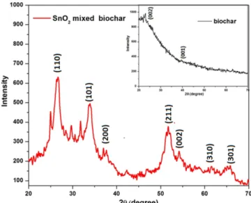
3-2. X-Ray Diffraction Analysis
The XRD analysis is employed to determine the crystallinity of SnO2 nanorods even if they are combined with biochar. The XRD pattern of the biochar is shown in the Fig. 2 below. It shows two broad peaks which can be indexed to (002) and (100) diffraction plane at Bragg’s angle 2θ of about 23° and 43°. Exhibition of two broad peaks and the absence of sharp peaks reveals a predomi- nantly amorphous structure of the prepared biochar. Wang et al. [1]
also reported similar diffraction pattern in identical (002) and (100)
planes, which leads to the conclusion that their material is amor- phous, which is in good agreement with our results as our material is also non-crystalline and amorphous. SnO2 shows diffraction peaks which have been in good agreement with the (JCPDS, no. 41-1445) corresponding to the tetragonal rutile structure of SnO2. It is evident from the X-ray diffraction pattern that the composites have diffraction peaks originating from SnO2 mixed biochar composite, thus con- firming the incorporation of SnO2 into biochar matrix. No obvious peaks related to biochar are observed in SnO2 mixed biochar com- posite.
3-3. UV-VIS Spectroscopy
The optical properties and interfacial interaction of SnO2 with biochar were ascertained by applying the UV-Vis spectrometer.
The absorbance spectrum of synthesized samples was recorded from 200 nm to 800 nm wavelength range in dimethyl formamide Fig. 1. FTIR spectra of biochar and SnO2 mixed biochar composite. Fig. 2. XRD pattern of biochar and SnO2 mixed biochar composite.
Fig. 3. UV-VIS spectra of biochar and SnO2 mixed biochar composite.
(DMF) as shown in Fig. 3. The broad absorption band seen in the UV region between 260-285 nm range is due to the presence of the aldehyde group in glucose molecule [36,37], which is an abundant sugar present in bananas [38,39]. It involves the excitation of elec- trons from bonding to antibonding π* orbital of the chromophore, C=O (either π-π* or n-π*) [37]. However, at longer wavelengths there are rather weak n-π* interactions, since the transition requires lower energy. The n-π* transition of aldehydes gives absorption with the values of λmax between 280 nm to 300 nm. The biochar sam- ple prepared containing the aldehyde group shows a maximum peak (λmax) at 280 nm, which is in good agreement with the values reported in literature. The absorption spectrum of SnO2 mixed bio- char is shown in Fig. 3 and the value of the absorption edge is 275 nm.
Considering the blue shift of the absorption position from the bulk SnO2, the absorption onset of the present sample can be assigned to the direct transition of electron in the SnO2 nano crystals. Bhagwat et al. reported that substantial decrease in absorption near the band edge for SnO2 nanocrystallites indicates the better crystallinity and lower defect density for synthesized thin film [40,41].
3-4. Morphological Studies 3-4-1. FESEM
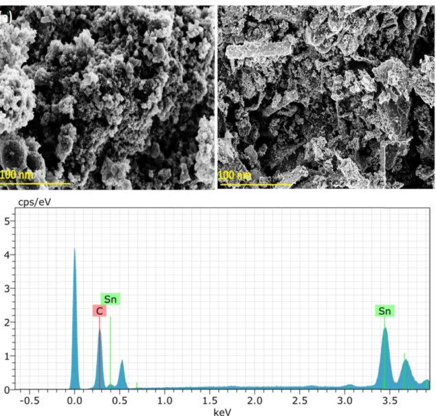
Fig. 4(a) and (b) represent the FESEM images of biochar at dif- ferent optical magnifications. The images illustrate the surface tex- ture and porosity on the surface. It depicts no particular crystalline structure of the prepared biochar. The light regions correspond to the carbon particles that are agglomerated and irregular in shape.
The primary particles show a tendency to form bigger aggregated particles. Fig. 4(a) shows the high porous structure that facilitates the electrolyte ions to go to the electrode material and aids in increasing the electrode and electrolyte interfaces [42]. Genovese et al. (2014) reported that increasing the porosity and surface area leads to abun- dant redox active functionalities present on electrode material. As reported in literature, hydrothermal-based biochar particles are nanostructured. Korhani and coworkers [43] reported that nano- structured particles are formed in micrometer to millimeter in size and partially in nanoscale range after hydrothermal treatment. Some small apertures existed with non-uniform pore distribution and dif- ferent pore sizes, which contributed to the rough surface, thereby
Fig. 4. FESEM micrographs of (a) biochar (b) SnO2 mixed biochar composite and (c) EDS analysis respectively.
increasing their specific surface area, while FESEM studies in Fig.
4(b) were also performed on dispersed powder samples of SnO2 mixed biochar composite displaying the formation of nanorod-like morphology with non-uniform particles of biochar [44].The nanorods might have grown at the expense of the small particles and might have aggregated, causing local defects in the present investigation.
Intimate contact between SnO2 nanorods and biochar carbon parti- cles was also confirmed by FESEM. This can be explained on the basis that SnO2 nanorods were successfully mixed and exhibited intimate contact with biochar carbon particles, thus rapid electron transfer [45,46].
The elemental composition of composite was characterized by energy-dispersive spectroscopy (EDS) in the form of individual ele- mental peaks; as shown in Fig. 4(c) the EDS pattern of composite demonstrates the existence of C and Sn and their atomic %-age is 90.01, and 9.99 , respectively.
3-4-2. HRTEM microscopy
SnO2 mixed biochar exhibits nanorod-like structure having rough and porous surface as displayed in Fig. 5(a) and (b). This porosity facilitates the access of electrolyte into the electrode material [47].
The average diameter of these nanorods is ~65~70 nm. However, SnO2 mixed biochar reveals a different morphology in which sur- face is covered systematically with sharp tips or needles along with formation of small flower-like microspheres. These nanorods or needles would affect the capacitance of the composite as they have high aspect ratio, which aids effective charge transport and ion dif- fusion [48].
From Fig. 5(c) SnO2 nanorods have a tetragonal rutile structure without any diffraction spots or rings related to secondary phases, confirmed on basis of the selected area electron diffraction pat- terns (SAED). These results are reliable and are in good agreement with those of the XRD phase analysis. Furthermore, the analysis of TEM images established and revealed the view that the nanorods in the present investigation might have grown at the expense of the small particles with the increasing annealing temperature and that the nanorods might have aggregated, leading to local defects [49- 51]. Wahid et al. (2013) reported that the aspect ratio of nanorods increased as the annealed temperature was increased. The surface area, pore size, and total volume of this composite were calculated by BET study (supplementary material Fig. S1 and S1 (b)) and found to have 376.2 m2g-1, 10.7 nm and 0.48 cm3 g-1, respectively.
3-4-3. Cyclic Voltammetric
Fig. 6(a) shows a comparative study of the cyclic voltammo- grams (CVs) for biochar and SnO2 mixed biochar composites at different scan rates of 10 mV s-1 to 50 mV s-1. However, when the scan rate exceeded 50 mV·s-1, the hysteresis area of the CVs of the composite electrodes was larger than that of the biocarbon electrodes.
For SnO2 mixed biochar and banana peel biochar (Fig. 6(c)), a spe- cific capacitance of 465 F g-1 and 260 F g-1 was obtained at the scan rate of 10 mV s-1 respectively, when the scan rate was increased to 50 mV s-1, the specific capacitance of SnO2 mixed biochar decreased by 22.4% to 360 F g-1. The enhanced electrochemical performance could be attributed to the following structural features. Mane et al.
reported [52] that first, SnO2 can absorb electrolyte cations (Na+) on the electrode surface from Na2SO4 electrolyte and thus provide more charge storage. Second, the easy access of SO32- by the SnO2 microspheres can be guaranteed by the hierarchical nature and lesser thickness of the nanosheets. Therefore, both Na+ and SO32- from the electrolyte are fully utilized in SnO2 electrode:
(SnO2)surface + Na+ + e− ↔ (SnO2−Na+)surface (3) As the scan rate increased, the current value was also increased, and the potential shift of the redox peaks with the variation of scan rate was insignificant [53].
During the slower voltage scan rate, a chemical adsorption/desorp- tion or redox reaction occurred on the surfaces of the electrodes, which facilitated electrolyte ions to penetrate into the inner pores of the electrode material. On the other hand, at a high scan rate the ions may not have enough time to reach the inner surface of the capacitor electrode and only accumulate on the outer surface of the material, resulting in decreased capacitance [54]. Therefore, a comparatively low scan rate demonstrates a better specific capacitance for devices. Thus we suggested, when the electrode material with a large specific sur- face area is adopted, the specific capacitance is increased [55-57].
3-4-4. Charge-Discharge Studies
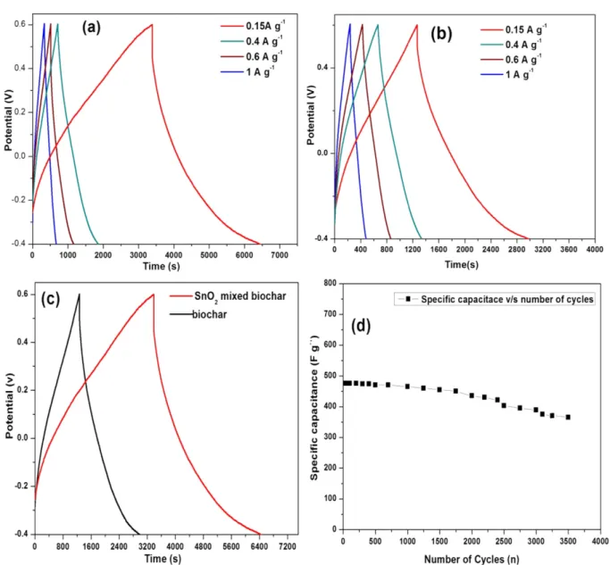
For SnO2 mixed biochar, the specific capacitance to 476 Fg-1 and Fig. 5. HRTEM micrographs (a) and (b)SnO2 mixed biochar com-
posite and (c) SAED pattern respectively.
361 Fg-1 for the current densities was 0.15 Ag-1 and 1 Ag-1, respectively (Fig. 7(a)). Genovese et al. reported galvanostatic charge-discharge curves for the natural and exfoliated biochar, which demonstrated the ideal linear voltage-time relation with a capacitance of 221 Fg-1 at 0.5 Ag-1 [58]. The specific capacitance observed for SnO2 mixed biochar composite was higher than that for biochar. These results manifest that the SnO2 mixed composite exhibits a much higher capacitive response than biochar, demonstrating that SnO2 mixing augments the electrochemical activity of biochar. The enhancement of capacitance may be ascribed to the one-dimensional nanorod struc- ture with large surface area and high length/diameter ratio [59,60].
One-dimensional nanorod structure of SnO2 could provide more
reaction sites on the surface, and the smaller diameter of the nanorods provides a short diffusion length for electrolyte ion insertion. This could enhance the charge transfer and electron conduction along the length direction [61,62]. The feasible electron transfer along with highly ordered SnO2 nanorods also promotes the reversible proton adsorption/desorption or redox reaction at the electrode and electrolyte interface. The high specific capacitance of SnO2 mixed biochar may be attributed to its higher surface area and rod-like permeable structure, which can propose short diffusion path length and additional active sites to ions/electrons of electrolyte, thus maximizing the utilization of the electrode materials resulting to high charging/discharging rates. The cyclic stability of the compos- Fig. 6. Cyclic voltametric curves of (a) SnO2 mixed biochar composite with scan rates from 10 to 50mV s-1 (b) biochar with scan rates from
10 to 50mV s-1 (c) Cyclic voltametric curves of biochar and SnO2 mixed biochar composite at 10 mV s-1 (d) Specific capacitance ver- sus scan rate plots of biochar and SnO2 mixed biochar, respectively.
ite electrode represents an important criterion for an electrochemi- cal supercapacitor [63]. Fig. 7(d) illustrates when the electrode was subjected to 3500 cycles at a current density of 0.15 A g-1. It retained 76.6% of its initial capacitance. Its ideal EDLC behavior contrib- utes to high electrochemical stability. A comparison of the specific capacitance obtained for SnO2 mixed biochar composite with the different materials is summarized in Table 1.
Electrochemical impedance spectroscopy (EIS) was used to determine the conductive characteristics of the electrode materials.
The respective Nyquist plots in Fig. 8 were obtained between Z’
and -Z” in frequency range of 1 Hz to 100 KHz [30]. The initial non- zero intercept of Z′ at the beginning of the semicircle is attributed to the equivalent series resistance (ESR) or electrical resistance of electrolyte (Rs) [64,65]. The equivalent series resistance (ESR) val- ues are determined to be 0.24 and 0.604 Ω for SnO2 mixed biochar and biochar, respectively.
These values include the total equivalent series resistance (ESR) of the ionic resistance of electrolyte, intrinsic resistance of elec- Fig. 7. Galvanostatic charge/discharge curves of (a) SnO2 mixed biochar composite and (b) biochar in 1M H2SO4 in different current density
at 0.15 A g-1, 0.3A g-1, 0.6A g-1 and 1 A g-1, respectively.(c) Galvanostatic charge/ discharge curves of biochar and SnO2 mixed biochar composite at 0.15 A g-1. (d) Cycle stability of biochar and SnO2 mixed biochar at 0.15 A g-1.
Table 1. Comparison of specific capacitance of SnO2 mixed biochar composite with different carbon composite
Electrode material Electrolyte Working electrode Reference Specific capacitance (F g-1)
N, S-co-doped Biochar 2M KOH Nickel foam current collector [1] 100.5
Exfoliated biochar 0.5 M H2SO4 Titanium foil current collector [58] 221 Pine needle-derived microporous nitrogen-doped carbon 1M Na2SO4 Pine needle carbon based electrodes [16] 236
Ni loaded biochar 0.5 M KOH Stainless Steel Wire [67] 123
At present work 1M H2SO4 Graphite current collector 476
trode material, and the contact resistance at the electrode material/
current collector interface. The curves seem to be straight lines at low frequency region and an arc in the high frequency region [66].
This shape is due to the electrochemical reaction at the interface of the electrode and electrolyte, corresponding to the charge-transfer resistance. A large semicircle is observed in EIS spectra biochar, indicating higher electrical resistance in biochar, which mainly depends on the electrode surface area and the inter particle resistiv- ity. The smaller semicircle for the SnO2 mixed biochar composite based electrode implies a lower charge-transfer resistance than in case of the based electrodes. On the realization of thin active layers or addition of some highly conductive additives can decrease this value and the electro chemical reaction between the electrode and the electrolyte occurs more easily, which leads to high specific capacitance. The high resistance of ion transfer in biochar might be accredited to low charge density, thus ensuing low capacitance. In contrast, SnO2 mixed biochar showed a short diffusion path length of ions in the electrolyte, which could be seen from the low resis- tance of the capacitive part on the Nyquist plot [63].
4. Conclusion
SnO2 mixed biochar composite derived from banana peel was prepared via chemical co-precipitation method. The outcome of SnO2 mixing confirmed with the help FESEM images is a change in morphology of biochar after introduction of SnO2 that exhibits nanorod-like shape. The results establish that the dispersed parti- cles of biochar carbon are anchored on the surface of SnO2 nanorods.
The biochar carbon particles at current density 0.15 Ag-1 delivered 476 F g-1 specific capacitance. Apparently, on addition of SnO2 into the biochar, specific cell capacitance was increased by 53.7%.
The integration of biochar and the needle-like SnO2 enables such
composites to possess good electrochemical behavior that is useful as electrode material for supercapacitors.
Acknowledgments
Authors are very grateful to University Grants Commission, New Delhi for providing financial assistance under the scheme of sup- port for major research project (F. No. 42-345/2013 (SR)).
References
1. Wang, L., Li, X., Ma, J., Wu, Q. and Duan, X., “Non-activated, N, S- co-doped Biochar Derived from Banana with Superior Capaci- tive Properties,” Sust. Energy., 2(2), 39-43(2014).
2. Pham, H. D., Pham, V. H., Oh, E.-S., Chung, J. S. and Kim, S.,
“Synthesis of Polypyrrole-reduced Graphene Oxide Composites by in-situ Photopolymerization and its Application as a Super- capacitor Electrode,” Korean Chem. Engg. Res., 29(1), 125-129 (2012).
3. Kim, K. M., Lee, Y. G. and Ko, J. M., “Electrochemical Proper- ties of Activated Carbon Supecapacitor Adopting Poly(acryloni- trile) Separator Coated by Polymer-alkaline Electrolytes,” Korean Chem. Engg. Res., 55(4), 467-472(2017).
4. Bagheri, A. R., Ghaedi, M., Asfaram, A., Jannesar, R. and Goudarzi, A., “Design and Construction of Nanoscale Material for Ultrasonic Assisted Adsorption of Dyes: Application of Derivative Spectro- photometry and Experimental Design Methodology,” Ultrason.
Sonochem., 35(a), 112-123(2017).
5. Machado, F. M., Bergmann, C. P., Fernandes, T. H., Lima, E. C., Royer, B., Calvete, T. and Fagan, S. B., “Adsorption of Reactive Red M-2BE Dye from Water Solutions by Multi-walled Carbon Nanotubes and Activated Carbon,” J. Hazard. Mater., 192(3), 1122-1131(2011).
6. Wang, H., Xu, Z., Kohandehghan, A., Li, Z., Cui, K., Tan, X., Stephenson, T. J., King’ondu, C. K., Holt, C. M. and Olsen, B.
C., “Interconnected Carbon Nanosheets Derived from Hemp for Ultrafast Supercapacitors with High Energy,” ACS Nano, 7(6), 5131-5141(2013).
7. Yao, Y. and Wu, F., “Naturally Derived Nanostructured Materials from Biomass for Rechargeable Lithium/sodium Batteries,”
Nano Energy., 17, 91-103(2015).
8. Song, S., Ma, F., Wu, G., Ma, D., Geng, W. and Wan, J., “Facile Self-templating Large Scale Preparation of Biomass-derived 3D Hierarchical Porous Carbon for Advanced Supercapacitors,” J.
Mater. Chem. A, 3(35), 18154-18162(2015).
9. Ma, G., Zhang, Z., Sun, K., Peng, H., Yang, Q., Ran, F. and Lei, Z., “White Clover Based Nitrogen-doped Porous Carbon for a High Energy Density Supercapacitor Electrode,” RSC Adv., 5 (130), 107707-107715(2015).
10. Wang, P., Qiao, B., Du, Y., Li, Y., Zhou, X., Dai, Z. and Bao, J.,
“Fluorine-doped Carbon Particles Derived from Lotus Petioles as High-performance Anode Materials for Sodium-ion Batter- ies,” J. Phys. Chem. C, 119(37), 21336-21344(2015).
11. Ding, J., Wang, H., Li, Z., Cui, K., Karpuzov, D., Tan, X., Kohan- dehghan, A. and Mitlin, D., “Peanut Shell Hybrid Sodium ion Capacitor with Extreme Energy-power Rivals Lithium ion Capaci- Fig. 8. Nyquist plots of biochar and SnO2 mixed biochar composite
respectively.
tors,” Energy Environ. Sci., 8(3), 941-955(2015).
12. Thangavel, R., Kaliyappan, K., Kang, K., Sun, X. and Lee, Y. S.,
“Going Beyond Lithium Hybrid Capacitors: Proposing a New High-performing Sodium Hybrid Capacitor System for Next- generation Hybrid Vehicles Made with Bio-inspired Activated Carbon,” Adv. Energy Mater., 6(7), 1-9(2016).
13. Peng, H., Ma, G., Sun, K., Zhang, Z., Yang, Q. and Lei, Z.,
“Nitrogen-doped Interconnected Carbon Nanosheets from Pom- elo Mesocarps for High Performance Supercapacitors,” Electro- chim. Acta., 190, 862-871(2016).
14. Yuan, H., Deng, L., Qi, Y., Kobayashi, N. and Tang, J., “Nonactivated and Activated Biochar Derived from Bananas as Alternative Cathode Catalyst in Microbial Fuel Cells,” Sci. World Journal., 2014, 1-8(2014).
15. Divyashree, A., Shoriya, A. B. A. M., Yallappa, S., Chaitra, K., Kathyayini, N., and Hegde, G., “Low Cost, High Performance Supercapacitor Electrode Using Coconut Wastes: Eco-friendly Approach,” J. Energy Chem., 25(5), 880-887(2016).
16. Zhu, G., Ma, L., Lv, H., Hu, Y., Chen, T., Chen, R., Liang, J., Wang, X., Wang, Y. and Yan, C., “Pine Needle-derived Microporous Nitrogen-doped Carbon Frameworks Exhibit High Performances in Electrocatalytic Hydrogen Evolution Reaction and Superca- pacitors,” Nanoscale, 9(3), 1237-1243(2017).
17. Thambidurai, A., Lourdusamy, J. K., John, J. V. and Ganesan, S.
“Preparation and Electrochemical Behaviour of Biomass Based Porous Carbons as Electrodes for Supercapacitors-a Comparative Investigation,” Korean J. Chem. Eng., 31(2), 268-275(2014).
18. Maurya, D. P., Singla, A. and Negi, S., “An Overview of Key Pretreatment Processes for Biological Conversion of Lignocel- lulosic Biomass to Bioethanol,” Biotech., 5(5), 597-609(2015).
19. Liu, Z. and Balasubramanian, R., “Upgrading of Waste Biomass by Hydrothermal Carbinization (HTC) and Low Temperature Pyroly- sis (LTP): a Comparative Evaluation,”115, 857-864(2014).
20. Chun, Y., Sheng, G., Chiou, C. T. and Xing, B., “Compositions and Sorptive Properties of Crop Residue-derived Chars,” Envi- ron. Sci. Technol., 38(17), 4649-4655(2004).
21. Wang, M., Sheng, G. and Qiu, Y., “A Novel Manganese-oxide/
Biochar Composite for Efficient Removal of Lead (II) from Aqueous Solutions,” Int. J. Environ. Sci. Technol., 12(5), 1719- 1726(2015).
22. Huang, X., Kim, M., Suh, H. and Kim, I., “Hierarchically Nano- structured Carbon-supported Manganese Oxide for High-perfor- mance Pseudo-capacitors,” Korean J. Chem. Eng., 33(7), 2228- 2234(2016).
23. Kouchachvili, L. and Entchev, E., “Ag/Biochar Composite for Supercapacitor Electrodes,” Mater. Today Energy., 6, 136-145(2017).
24. Yao, W., Zhou, H. and Lu, Y., “Synthesis and Property of Novel MnO2@polypyrrole Coaxial Nanotubes as Electrode Material for Supercapacitors,” J. Power Sources., 241, 359-366(2013).
25. Sultana, S., Kishore, D., Kuniyil, M., Khan, M., Siddiqui, M. R.
H., Alwarthan, A., Prasad, K., Ahmad, N. and Adil, S. F., “Pro- moting Effects of Thoria on the Nickel-manganese Mixed Oxide Catalysts for the Aerobic Oxidation of Benzyl Alcohol,” Arab. J.
Chem., 10(4), 448-457(2017).
26. Varala, R., Narayana, V., Kulakarni, S. R., Khan, M., Alwarthan, A.
and Adil, S. F., “Sulfated tin Oxide (STO)-Structural Properties and Application in Catalysis: A Review,” Arab. J. Chem., 9(4),
550-573(2016).
27. Zhao, Y., Rana, W., Xiong, D.-B., Zhang, L., Xu, J. and Fam- ing, G., “Synthesis of Sn-doped Mn3O4/C Nanocomposites as Supercapacitor Electrodes with Remarkable Capacity Retention,”
Mater. Lett., 118, 80-83(2014).
28. Channu, V. S. R., Holze, R., Wicker Sr, S. A., Walker Jr, E. H., Williams, Q. L. and Kalluru, R. R., “Synthesis and Characteri- zation of (Ru-Sn)O2 Nanoparticles for Supercapacitors,” Mater.
Sci. Appl., 2(9), 1175-1179(2011).
29. Sun, P., Hui, C., Khan, R. A., Du, J., Zhang, Q. and Zhao, Y.-H.,
“Efficient Removal of Crystal Violet Using Fe3O4-coated Bio- char: the Role of the Fe3O4 Nanoparticles and Modeling Study Their Adsorption Behavior,” Sci. Rep., 5, 12638(2015).
30. Chaudhary, G., Sharma, A. K., Bhardwaj, P., Kant, K., Kaushal, I. and Mishra, A. K., “NiCo2O4 Decorated PANI-CNTs Com- posites as Supercapacitive Electrode Materials,” J. Energy Chem., 26(1), 175-181(2017).
31. Ragupathy, S. and Sathya, T., “Synthesis and Characterization of SnO2 Loaded on Groundnut Shell Activated Carbon and Photo- catalytic Activity on MB Dye Under Sunlight Radiation,” J. Mater.
Sci. Mater. Electron., 27(6), 5770-5778(2016).
32. Hesas, R. H., Arami-Niya, A., Daud, W. M. A. W. and Sahu, J.,
“Preparation and Characterization of Activated Carbon from Apple Waste by Microwave-assisted Phosphoric Acid Activation:
Application in Methylene Blue Adsorption,” BioResour., 8(2), 2950-2966(2013).
33. Gundrizer, T. and Davydov, A., “IR Spectra of Oxygen Adsorbed on SnO2,” Reaction Kinet. Catal. Lett., 3(1), 63-70(1975).
34. Gu, F., Wang, S. F., Song, C. F., Lü, M. K., Qi, Y. X., Zhou, G.
J., Xu, D. and Yuan, D. R., “Synthesis and Luminescence Proper- ties of SnO2 Nanoparticles,” Chem. Phys. Lett., 372(3), 451-454 (2003).
35. Zhou, J., Zhang, M., Hong, J., Fang, J. and Yin, Z., “Structural and Spectral Properties of SnO2 Nanocrystal Prepared by Micro- emulsion Technique,” Appl. phys. A, 81(1), 177-182(2005).
36. Launcr, H., Wilson, W. and Flynn, J. H., “Determination of Glu- cose by Means of Sodium Chlorite,” J. Res. Natl. Bur. Stand., 51, 5(1953).
37. Launcr, H., Wilson, W. and Flynn, J. H., “Determination of Glu- cose by Means of Sodium Chlorite,” J. Res. Natl. Bur. Stand., 51(5), 237-245(1953).
38. Tapre, A. and Jain, R., “Study of Advanced Maturity Stages of Banana,” Int. J. Adv. Eng. Res. Stud, 1 (3), 272-274(2012).
39. Kumar, K. S. and Bhowmik, D., “Traditional and Medicinal Uses of Banana,” J. Pharmacogn. Phytochem., 1, 3(2012).
40. Gu, F., Wang, S. F., Lu, M. K., Zhou, G. J., Xu, D. and Yuan, D.
R., “Photoluminescence Properties of SnO2 Nanoparticles Syn- thesized by Sol-gel Method,” J. Phys. Chem. B., 108(24), 8119- 8123(2004).
41. Bhagwat, A. D., Sawant, S. S., Ankamwar, B. G. and Mahajan, C. M., “Synthesis of Nanostructured tin Oxide (SnO2) Powders and Thin Films by Sol-gel Method,” J. Nano Electron. Phys., 7(4), 4037-4031(2015).
42. Genovese, M., Jiang, J., Lian, K. and Holm, N., “High Capacitive Performance of Exfoliated Biochar Nanosheets from Biomass Waste Corn Cob,” J. Mater. Chem. A., 2015(3), 2903-2913(2014).
43. El Korhani, O., Zaouk, D., Cerneaux, S., Khoury, R., Khoury, A.
and Cornu, D., “Synthesis and Performances of Bio-sourced Nanostructured Carbon Membranes Elaborated by Hydrother- mal Conversion of Beer Industry Wastes,” Nanoscale Res. Lett., 8(121), 3-11(2013).
44. Li, X., Li, T., Zhong, Q., Zhang, X., Li, H. and Huang, J., “A Hybrid of SnO2 Nanorods Interlaced by Unzipped Carbon Nano- tube to Enhance Electrochemical Properties for Lithium ion Bat- tery,” Mater. Lett., 130, 232-235(2014).
45. Wang, L., Shen, L., Zhu, L., Jin, H., Bing, N. and Wang, L., “Prepa- ration and Photocatalytic Properties of SnO2 Coated on Nitro- gen-doped Carbon Nanotubes,” J. Nanomater., 2012, 32(2012).
46. Chen, S., Xin, Y., Zhou, Y., Zhang, F., Ma, Y., Zhou, H. and Qi, L., “Branched CNT@ SnO2 Nanorods@ Carbon Hierarchical Heterostructures for Lithium ion Batteries with High Reversibil- ity and Rate Capability,” J. Mater. Chem. A, 2(37), 15582- 15589(2014).
47. Salunkhe, R. R., Jang, K., Yu, H., Yu, S., Ganesh, T., Han, S.-H.
and Ahn, H., “Chemical Synthesis and Electrochemical Analy- sis of Nickel Cobaltite Nanostructures for Supercapacitor Appli- cations,” J. Alloys Compd., 509(23), 6677-6682(2011).
48. Wang, K., Wu, H., Meng, Y. and Wei, Z., “Conducting Polymer Nanowire Arrays for High Performance Supercapacitors,” Small, 10(1), 14-31(2014).
49. Sun, J. Q., Wang, J. S., Wu, X. C., Zhang, G. S., Wei, J. Y., Zhang, S. Q., Li, H. and Chen, D. R., “Novel Method for High- yield Synthesis of Rutile SnO2 Nanorods by Oriented Aggrega- tion,” Cryst. Growth Des., 6(7), 1584-1587(2006).
50. Shaziman, S., Ismail, A. S., Mamat, M. H. and Zoolfakar, A. S.,
“Influence of Growth Time and Temperature on the Morphology of Zno Nanorods via Hydrothermal,” IOP Publishing, City., 99(4), 012016(2015).
51. Wahid, K. A., Lee, W. Y., Lee, H. W., Teh, A. S., Bien, D. C. S.
and Azid, I. A., “Effect of Seed Annealing Temperature and Growth Duration on Hydrothermal ZnO Nanorod Structures and Their Electrical Characteristics,” Appl. Surf. Sci., 283(15), 629- 635(2013).
52. Mane, R. S., Chang, J., Ham, D., Pawar, B. N., Ganesh, T., Cho, B. W., Lee, J. K. and Han, S.-H., “Dye-sensitized Solar Cell and Electrochemical Supercapacitor Applications of Electrochemi- cally Deposited Hydrophilic and Nanocrystalline tin Oxide Film Electrodes,” Curr. Appl. Phys., 9(1), 87-91(2009).
53. Jiang, J., Zhang, L., Wang, X., Holm, N., Rajagopalan, K., Chen, F.
and Ma, S., “Highly Ordered Macroporous Woody Biochar with Ultra-high Carbon Content as Supercapacitor Electrodes,” Elec- trochim. Acta, 113, 481-489(2013).
54. Chen, L.-F., Zhang, X.-D., Liang, H.-W., Kong, M., Guan, Q.-F., Chen, P., Wu, Z.-Y. and Yu, S.-H., “Synthesis of Nitrogen-doped Porous Carbon Nanofibers as an Efficient Electrode Material for Supercapacitors,” ACS Nano, 6(8), 7092-7102(2012).
55. Zheng, J. and Jow, T., “A New Charge Storage Mechanism for Electrochemical Capacitors,” J. Electrochem. Soc., 142(1), L6- L8(1995).
56. Srinivasan, V. and Weidner, J. W., “An Electrochemical Route for Making Porous Nickel Oxide Electrochemical Capacitors,”
J. Electrochem. Soc., 144(8), L210-L213(1997).
57. Lin, C., Ritter, J. A. and Popov, B. N., “Development of Carbon- metal Oxide Supercapacitors from Sol-gel Derived Carbon-ruthe- nium Xerogels,” J. Electrochem. Soc., 146(9), 3155-3160(1999).
58. Genovese, M., Jiang, J., Lian, K. and Holm, N., “High Capaci- tive Performance of Exfoliated Biochar Nanosheets from Bio- mass Waste Corn Cob,” J. Mater. Chem. A, 3(6), 2903-2913(2015).
59. Lei, Z., Sun, X., Wang, H., Liu, Z. and Zhao, X., “Platelet CMK-5 as an Excellent Mesoporous Carbon to Enhance the Pseudoca- pacitance of Polyaniline,” ACS Appl. Mater. Interfaces., 5(15), 7501-7508(2013).
60. Chen, H., Zhou, S., Chen, M. and Wu, L., “Reduced Graphene Oxide-MnO2 Hollow Sphere Hybrid Nanostructures as High- performance Electrochemical Capacitors,” J. Mater. Chem., 22(48), 25207-25216(2012).
61. Kim, J. G., Nam, S. H., Lee, S. H., Choi, S. M. and Kim, W. B.,
“SnO2 Nanorod-planted Graphite: an Effective Nanostructure Configuration for Reversible Lithium ion Storage,” ACS Appl.
Mater. Interfaces., 3(3), 828-835(2011).
62. Park, M.-S., Wang, G.-X., Kang, Y.-M., Wexler, D., Dou, S.-X.
and Liu, H.-K., “Preparation and Electrochemical Properties of SnO2 Nanowires for Application in Lithium-ion Batteries,” Angew.
Chem., 119(5), 764-767(2007).
63. Liu, Y., Jiao, Y., Zhang, Z., Qu, F., Umar, A. and Wu, X., “Hier- archical SnO2 Nanostructures Made of Intermingled Ultrathin Nanosheets for Environmental Remediation, Smart Gas Sensor, and Supercapacitor Applications,” ACS Appl. Mater. Interfaces, 6(3), 2174-2184(2014).
64. Yang, X., Zhu, J., Qiu, L. and Li, D., “Bioinspired Effective Pre- vention of Restacking in Multilayered Graphene Films: Towards the Next Generation of High-performance Supercapacitors,” Adv.
Mater., 23(25), 2833-2838(2011).
65. Kim, C., Ngoc, B. T. N., Yang, K. S., Kojima, M., Kim, Y. A., Kim, Y. J., Endo, M. and Yang, S. C., “Self-sustained Thin Webs Consisting of Porous Carbon Nanofibers for Supercapacitors via the Electrospinning of Polyacrylonitrile Solutions Containing Zinc Chloride,” Adv. Mater., 19(17), 2341-2346(2007).
66. Xiao, F. and Xu, Y., “Electrochemical co-deposition and Char- acterization of MnO2/SWNT Composite for Supercapacitor Appli- cation,” J. Mater. Sci. - Mater. Electron., 24(6), 1913-1920(2013).
67. Wang, Y., Zhang, Y., Pei, L., Ying, D., Xu, X., Zhao, L., Jia, J.
and Cao, X., “Converting Ni-loaded Biochars Into Supercapac- itors: Implication on the Reuse of Exhausted Carbonaceous Sor- bents,” Sci. Rep., 7, (2017).
Supporting Information
1. BET surface
The BET surface area of the SnO2 mixed biochar composite is 376.2 m2g-1, and the larger value may be attributed to the hierarchi-
cal morphologies of the prepared composite. The pore size distribu- tion of 10.7 nm nm of the prepared sample could originate from the gap between the adjacent small nanostructures.
Fig. S1. (a) Nitrogen adsorption and desorption isotherm plot SnO2 Mixed banana biochar composite. (b) Pore distribution of SnO2 Mixed banana biochar composite.