에너지 저장용 고속회전기의 실험적 평가
Experimental Evaluation of an Energy Storage Device with High Rotaional
Speed
이준호
†Jun-Ho Lee
Key Words : Energy storage system(에너지 저장 시스템), High rotational Speed(고속회전), Magnetic
bear-ing(자기베어링)
ABSTRACT
Experimantal evaluation of an energy storage device with high rotational speed to store regenerative energy which might be generated during the braking period of the trains is presented. The proposed ESS is small scale model and has 5kW output power, high rotational speed. In general railway trains generate regenerative energy for 10-20 sec when the train brakes and also high traction energy is needed for very short moment (10 sec) when the train increases the traction force. Considering such characteristics of the railway system energy storage device for the railway should have very fast response property. Among the various energy storage devices flywheel energy storage system has the fastest response property, which means that flywheel ESS is the most suitable for the railway system.
1)
1. Introduction
Energy storage device with high rotational speed (flywheel energy storage device) is used to store excess electrical energy into mechanical rotational energy. The stored rotational energy is converted into electrical energy to supply that energy to the electrical machines etc. when it is needed. In order to make energy conversion between the electrical and mechanical energy or
mechanical and electrical energy a power
conversion device, high speed rotational flywheel to store rotational energy, rotational rotor, bearings to support the high speed rotational rotor, and
† 교신저자; 정회원, 한국철도기술연구원 E-mail : [email protected]
Tel : 031-460-5040, Fax :031-460-5034
housing are needed.
In general railway trains generate regenerative energy for 10-20 sec when the train brakes, on the other hand high traction energy is needed for very short moment (10 sec) when the train increases the traction force. Considering such characteristics of the railway system energy storage system for the railway should have very fast response property. Among the various energy storage systems flywheel energy storage system has the fastest response property, which means that flywheel ESS is the most suitable for the railway system.
In this paper the system configuration for the flywheel ESS including operational system for the energy conversion and the design of small-scale flywheel energy storage system (five-degrees-of -freedoms) supported by magnetic bearings are presented. The effectiveness of the proposed 한국소음진동공학회 2014년 추계학술대회
flywheel energy storage system is shown based on the high speed rotational test and also the applicability of the proposed configurations to the railway system is presented by using the energy conversion of the flywheel energy storage system that indicates the charging of the regenerative energy and discharging for the traction force based on the load test.
2. System Configuration
Fig. 1 shows the overall system configuration that consists of flywheel system, vacuum pump, and levitation controller. The flywheel system has the flywheel rotor and the housing that rotational motor stator, upper, lower, and thrust magnetic bearings are to be installed in it. The vacuum pump is connected with the housing to make vacuum the inside of the hosing, which increase the efficiency of the power conversion. The levitation controller levitates the rotor and controls the vibration of the rotor during the high speed rotation.
Fig. 1. FESS (Flywheel Energy Storage System) configuration
3. Analysis of the Rotational Rotor One of the important issues in the design of
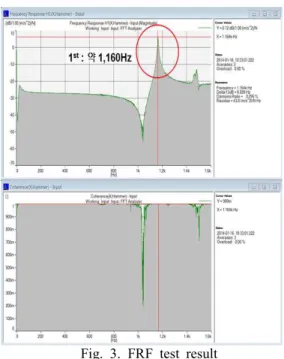
the flywheel energy storage system is to design and to analysis of the rotational rotor. Fig. 2 shows the shape of the rotational rotor. The rotational rotor is composed of the upper and lower radial bearing to support the rotor in the radial direction, the thrust plate which is used for the levitation of the rotor in the horizontal direction, the flywheel to store the rotational energy, and the PM type motor to make the rotor rotate. Fig. 3 shows the FRF(Frequency Response Function) test result that has been produced from the general natural frequency test using the impact hammer. As seen in the figure the first mode is at 1,160Hz (69,600rpm).
Fig. 2. Shape of the rotational rotor
Fig. 3. FRF test result
Fig. 4. Rotational modes analysis Fig . 4 presents the measured data to analyze the relations between the rotational speed and the natural mechanical modes that appear in the rotational machine when the rotor rotates in high speed. Fig. 4 indicates that the first natural frequency appears at 1,050Hz ~ 1,100Hz, and the rotational speed in that frequency is 10,000rpm ~
12,000rpm that meets the 5th and 6th mechanical
modes and makes the amplitude of the rotational vibration at these modes be increased. Based on these analyses the rotational speed is set to 12,000rpm to avoid the mechanical resonance in
this paper. The 1st natural frequency in the FRF
test is 1,160Hz and the 1st natural frequency in
the rotational mode test is 1,050Hz ~ 1,100Hz. The 60Hz frequency difference is considered as measuring error.
4. Experimental Results
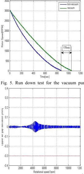
Fig. 5 shows the run down test results for the vacuum pump when the speed of the rotor has been increased up to the 3,000[rpm]. In the figure the blue line and the green line are for the non- vacuum and vacuum, respectively. The blue line reaches to zero speed in 178[sec] faster than that of the green line, which means the rotor rotates longer time in the vacuum.
Fig. 5. Run down test for the vacuum pump
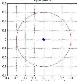
Fig. 6. Rotational speed test(12,000rpm) Fig 6 and 7 are the rotational test results at
12,000[rpm] that show 0.01[mm] vibration
amplitude, which means that the rotational rotor is in very good centering position. Natural frequency at 4,400[rpm] (rigid mode) causes the higher vibration amplitude. In these figures the red line indicates the nominal air gap distance, 0.3[mm]. Fig. 8 presents the output power for the different load level. In case of 4[W] the output power at 12,000[rpm] is 3.6[kW] and it is reduced to about
96[W] at the rotational speed 1,769[rpm].
However for the lower load level (6[W] or 10[W]) than 4[W] the rotational speed to reach to
about 96[W] is higher than that of the 4[W] load level, which means that higher load can use more energy.
Fig. 7. Rotational speed test(12,000rpm)
Fig. 8. Output power for the different load level
5. Conclusions
In this paper experimental evaluation for the energy storage device with high speed was presented. The design and analysis of the rotational rotor for the flywheel ESS, and the preliminary rotational test results were shown.
Output power versus different load level tests were also performed and indicated that higher load can use more energy.
In the future to define the FESS efficiency various experimental tests will be performed.
References
[1] Jun-Ho Lee, etal. “A Study on the Design
Procedure of the Eight Pole Magnetic
Bearings for the Inner-rotor and the
Outer-rotor type”, Journal of Electrical
Engineering Technology, vol. 8-6, pp.
1424-1430, 2013.
[2] G. Schweitzer and E. H. Maslen, eds., Magnetic Bearings: Theory, Design, and Application to Rotating Machinery, Springer, 2010.
[3] G. Schweitzer, H. Bleuler, A. Traxler, “Active Magnetic Bearings: Basics, Properties and Applications of Active Magnetic Bearings”,
vdf Houchschulverlag AG der ETH
Zurich,1994.
[4] J.H. Lee, A study on an effect of the flux feedback on an open-loop characteristic of the
magnetic levitation system, in: 13th
International Symposium on Magnetic
Bearings, Washington, Virginia, USA, Aug. 6-8, 2012.
[5] Alan Palazzolo, et.al., “Aero Gravity Test of
a 40,000RPM Flywheel”, 13th ISMB,
Arlington, Virginia, USA, August, 2012