Evaluation of strategic uprighting of the
mandibular molars using an orthodontic miniplate
and a nickel-titanium reverse curve arch wire:
Preliminary cephalometric study
Objective: To evaluate the overall treatment effects in terms of the amount of uprighting with changes in the sagittal and vertical positions of mandibular molars after applying an orthodontic miniplate with a nickel-titanium (NiTi) reverse curve arch wire (biocreative reverse curve [BRC] system). Methods: A total of 30 female patients (mean age, 25.99 ± 8.96 years) were treated with the BRC system (mean BRC time, 10.3 ± 4.07 months). An I-shaped C-tube miniplate (Jin Biomed) was placed at the labial aspect for the alveolar bone of the mandibular incisors. A 0.017 × 0.025-inch NiTi reverse curve arch wire was engaged at the C-tube mini-plate anteriorly and the first and second premolars and molars posteriorly in the mandibular arch. Pre- and post-BRC lateral cephalograms were analyzed. A paired t-test was used to analyze the treatment effects of BRC. Results: The mandibular second molars were intrusively uprighted successfully by the BRC system. Distal uprighting with a controlled vertical dimension was noted on the first molars when they remained engaged in the BRC and the distal ends of the arch wire were laid on the second molars. The mandibular first and second premolars showed a slight extrusion. The changes in the mandibular incisors were unremarkable, while the mandibular molar angulation improved significantly. The lower occlusal plane rotated counterclockwise (MP-LOP: 1.13° ± 2.60°). Conclusions: The BRC system can provide very effective molar uprighting without compromising the position of the mandibular anterior teeth. [Korean J Orthod 2021;51(3):179-188]
Key words: Molar uprighting, C-tube miniplate, Biocreative reverse curve, Intrusion Jae-Hyun Parka HyeRan Choob Jin-Young Choia Kyu-Rhim Chunga Seong-Hun Kima
aDepartment of Orthodontics, Graduate
School, Kyung Hee University, Seoul, Korea
bDepartment of Plastic Surgery,
Stanford University School of Medicine, Lucile Packard Children’s Hospital, Palo Alto, CA, USA
Received July 29, 2020; Revised October 9, 2020; Accepted October 28, 2020.
Corresponding author: Seong-Hun Kim.
Professor and Head, Department of Orthodontics, Graduate School, Kyung Hee University, 26 Kyungheedae-ro, Dongdaemun-gu, Seoul 02447, Korea.
Tel +82-2-958-9392 e-mail [email protected]
Jae-Hyun Park and HyeRan Choo contributed equally to this work (as co-first authors).
How to cite this article: Park JH, Choo HR, Choi JY, Chung KR, Kim SH. Evaluation of strategic uprighting of the mandibular molars using an orthodontic miniplate and a nickel-titanium reverse curve arch wire: Preliminary cephalometric study. Korean J Orthod 2021;51:179-188.
© 2021 The Korean Association of Orthodontists.
This is an Open Access article distributed under the terms of the Creative Commons Attribution Non-Commercial License (http://creativecommons.org/licenses/by-nc/4.0) which permits unrestricted non-commercial use, distribution, and reproduction in any medium, provided the original work is properly cited.
pISSN 2234-7518 • eISSN 2005-372X https://doi.org/10.4041/kjod.2021.51.3.179
INTRODUCTION
In orthodontics, uprighting of mesially angulated terior teeth is often necessary; in this process, the pos-terior teeth are attempted to be set up with respect to the basal bone to provide a stable occlusion and ensure better periodontal health.1,2 Many clinical options are available for mesially tipped mandibular posterior teeth, including conventional biomechanics using an auxiliary helix for the uprighting spring, a compressed coil spring, or various loop configurations.3-5 These systems, how-ever, are associated with adverse effects such as undesir-able movements of the anchor teeth and failure of verti-cal dimension control.6,7 Temporary skeletal anchorage devices (TSADs) are now widely used to overcome these unwanted adverse effects of conventional biomechan-ics.8 Among the currently available TSADs, the biocre-ative reverse curve (BRC), a novel biomechanical system using an anterior orthodontic miniplate combined with a nickel-titanium (NiTi) reverse curve arch wire has been proposed for uprighting the mandibular posterior teeth bilaterally.9 The BRC setup involves the placement of an I-shaped C-tube miniplate at the labial aspect of the alveolar bone of the mandibular incisors to maintain the vertical position of the anterior curvature of the reverse curve arch wire without engaging the mandibular ante-rior teeth in the reverse curve arch wire. Only the man-dibular posterior teeth are engaged in the reverse curve arch wire. A brass wire connector is often necessary to support the anterior part of the reverse curve to maxi-mize the curvature of the distal ends of the arch wire. A bonded lingual arch connecting the first premolars from one side all the way to the other is used to prevent the buccal flaring of the mandibular premolars and to reinforce the anchor value while the reverse curve is ex-pressed at the distal ends (Figure 1).
The purpose of this preliminary cephalometric study is to evaluate the overall treatment effects in terms of the amount of uprighting with changes in the sagittal and
vertical positions of mandibular molars after applying an orthodontic miniplate with a NiTi reverse curve arch wire as an effective alternative to the conventional mo-lar uprighting biomechanics. The null hypothesis is that the pre- and post-BRC sagittal and vertical positions of mandibular molars show significant differences.
MATERIALS AND METHODS
This study was approved by the Institutional Review Board at the Kyung Hee University Dental Hospital (KH-DT19016). Sample size calculation (G*Power version 3.1.9.2; Universität Düsseldorf, Düsseldorf, Germany) for an expected r = 0.6 corresponding to a large effect size revealed an expected sample size of 24 participants with a first-type error of 0.05 and an 80% power. Thus, 30 patients were enrolled in this study. The lateral cephalo-grams of 30 female patients who underwent orthodon-tic treatment using the BRC system were analyzed ret-rospectively. The first lateral cephalogram was obtained as part of the preliminary patient examination before initiating the orthodontic treatment (T1). The second cephalogram was obtained after utilization of the BRC system was complete (T2). When the BRC system was no longer needed, the brackets were placed on the mandib-ular anterior teeth and included in the continuous arch wire in the mandibular arch. For this study, we selected participants who had completed their growth, and re-ceived dental camouflage treatment (i.e., the treatment plan did not include orthognathic surgery) without en-gaging the mandibular anterior dentition while the BRC was applied in the mandibular arch. A total of 30 female participants with a mean age of 25.99 years at T1 were selected for the study.
For all selected subjects, uprighting of the mandibular molars was the priority in ensuring favorable orthodon-tic treatment outcomes. In order to achieve this objec-tive, 0.022-inch (in) preadjusted brackets (Quicklear with Tweemac prescription; FORESTADENT Bernhard
A B C
Figure 1. Schematic illustration of the biocreative reverse curve system. The C-tube miniplate is installed on the labial
side of the anterior teeth in the symphysis area. The brackets are bonded on the mandibular posterior target teeth. A 0.017 × 0.025-inch reverse curve of Spee nickel-titanium arch wire is raised by the C-tube and the intrusive upright force would be induced to the molars. A, Frontal view. B, Lateral view. C, Occlusal view.
Förster GmbH, Pforzheim, Germany) were placed on the mandibular premolars and molars. A passive lingual transverse arch was bonded on the lingual surface of the right and left mandibular first premolars to stabilize the transverse dimension of the mandibular arch while BRC is in effect. A 0.017 × 0.025-in reverse curve NiTi wire (Titanol curve of Spee; FORESTADENT Bernhard Förster GmbH) was then engaged in the mandibular posterior teeth. Instead of the anterior brackets, the anterior part of the reverse curve arch wire was held up by the I-shaped C-tube miniplate (JBOP001; Jin Biomed Co., Bu-cheon, Korea), and a brass wire connector at the labial surface of the anterior mandible.
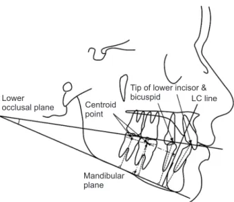
For quantitative evaluation of the lateral cephalo-grams, four reference points were marked. Six angular and ten linear comparative measurements were then obtained (Table 1).10,11 Figure 2 illustrates the well-established dentoalveolar measurement parameters. To determine the horizontal and vertical movement of the mandibular posterior teeth, the point centroid was used. The centroid is defined as the midpoint between the mesial and distal height of the contours of the crown. The cusp tip is a reference point for determining the amount of movement of the premolars and incisors. The reference line for the measurement of the antero-posterior tooth movement was the mandibular lingual cortex. The vertical position of the tooth was assessed by measuring the shortest distance from the centroid to
the mandibular plane (MP). The mesiodistal angulation of the mandibular posterior teeth was measured by de-termining the inclination of the tooth’s long axis to the MP.
Table 1. Definitions of cephalometric measurement values
Measurement Definition
Occlusal plane measurements
MP-LOP (Lower occlusal plane) (°) Angle of lower occlusal plane to mandibular plane Dentoalveolar measurements
L1-LC (mm) Distance from the lower central incisor to the lingual cortex L1-MP (mm) Distance from the lower central incisor to mandibular plane L1-MP (°) Mandibular lower central incisor inclination
L4-LC (mm) Distance from the first premolar to the lingual cortex L4-MP (mm) Distance from the first premolar to mandibular plane L4-MP (°) Mandibular first premolar inclination
L5-LC (mm) Distance from the second premolar to the lingual cortex L5-MP (mm) Distance from the second premolar to mandibular plane L5-MP (°) Mandibular second premolar inclination
L6-LC (mm) Distance from the first molar to the lingual cortex L6-MP (mm) Distance from the first molar to mandibular plane L6-MP (°) Mandibular first molar inclination
L7-LC (mm) Distance from the second molar to the lingual cortex L7-MP (mm) Distance from the second molar to the mandibular plane L7-MP (°) Mandibular second molar inclination
Figure 2. Reference points and lines used for
cephalo-metric analysis. Dentoalveolar (containing occlusal plane) measurements.
LC, mandibular lingual cortex.
Lower
occlusal plane Centroid point
Tip of lower incisor & bicuspid LC line
Mandibular plane
Statistical analysis
All data were captured by an experienced orthodon-tist (J.H.P). These data were confirmed by repeating the same data-collection process two weeks later. To verify the reliability of the measurements, intra-class correla-tion coefficient (ICC) was calculated. The measured cephalometric data were reliable because the ICC was greater than 0.95 at 95% confidence interval. Statisti-cal analyses were performed using SPSS ver. 22.0 (IBM Corp., Armonk, NY, USA). The normal distribution of all measured data was confirmed by using the Shapiro–Wilk test (p > 0.05). Paired t-tests were used to determine the statistical difference between T1 and T2 in each subject. A p-value of < 0.05 was regarded as statistically signifi-cant.
RESULTS
For the study population, the mean BRC period was 10.3 ± 4.07 months. The cephalometric changes be-tween T1 and T2 are listed in Table 2. The first and sec-ond molars uprighted significantly, as represented by the
reduced inclination of the tooth axis (p < 0.001). The first molars did not show statistically different move-ment, while the second molars showed a statistically significant 1.42-mm intrusion. All molars, premolars, and incisors showed distal movement: the incisors by 0.48 mm, the first premolars by 0.94 mm, second pre-molars by 0.56 mm, the first pre-molars by 1.01 mm, and the second molars by 0.53 mm. The first and second premolars showed a slight extrusion of 0.75 and 0.58 mm, respectively. The lower occlusal plane was rotated counterclockwise (MP-LOP: 1.13° ± 2.60°).
In addition to these statistical findings, one exemplary case was introduced to show the clinical usefulness of the BRC system. Figures 3 and 4 show the changes in the mandibular posterior teeth from the beginning to the final stage of the treatment, respectively. The 17-year-old-female patient’s chief complaint was mod-erate anterior dental crowding. The clinical and radio-graphic examinations confirmed that the patient had a skeletal Class II hyperdivergent pattern, anterior protru-sion, overjet of 8 mm, a deep curve of Spee with mesial angulation of mandibular posterior teeth, and a medical
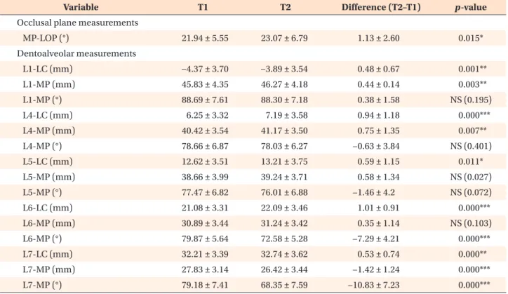
Table 2. Comparisons of cephalometric measurement values before (T1) and after (T2) the biocreative reverse curve
procedure
Variable T1 T2 Difference (T2–T1) p-value
Occlusal plane measurements
MP-LOP (°) 21.94 ± 5.55 23.07 ± 6.79 1.13 ± 2.60 0.015* Dentoalveolar measurements L1-LC (mm) −4.37 ± 3.70 −3.89 ± 3.54 0.48 ± 0.67 0.001** L1-MP (mm) 45.83 ± 4.35 46.27 ± 4.18 0.44 ± 0.14 0.003** L1-MP (°) 88.69 ± 7.61 88.30 ± 7.18 0.38 ± 1.58 NS (0.195) L4-LC (mm) 6.25 ± 3.32 7.19 ± 3.58 0.94 ± 1.18 0.000*** L4-MP (mm) 40.42 ± 3.54 41.17 ± 3.50 0.75 ± 1.35 0.007** L4-MP (°) 78.66 ± 6.87 78.03 ± 6.27 −0.63 ± 3.84 NS (0.401) L5-LC (mm) 12.62 ± 3.51 13.21 ± 3.75 0.59 ± 1.15 0.011* L5-MP (mm) 38.66 ± 3.99 39.24 ± 3.71 0.58 ± 1.34 NS (0.027) L5-MP (°) 77.47 ± 6.82 76.01 ± 6.88 −1.46 ± 4.2 NS (0.072) L6-LC (mm) 21.08 ± 3.31 22.09 ± 3.46 1.01 ± 0.91 0.000*** L6-MP (mm) 30.89 ± 3.44 31.24 ± 3.42 0.35 ± 1.14 NS (0.103) L6-MP (°) 79.87 ± 5.64 72.58 ± 5.28 −7.29 ± 4.21 0.000*** L7-LC (mm) 32.21 ± 3.39 32.74 ± 3.62 0.53 ± 0.74 0.000** L7-MP (mm) 27.83 ± 3.14 26.42 ± 3.44 −1.42 ± 1.24 0.000*** L7-MP (°) 79.18 ± 7.41 68.35 ± 7.59 −10.83 ± 7.23 0.000*** Values are presented as mean ± standard deviation.
Paired t-test was performed. NS, not significant.
*p < 0.05; **p < 0.01; ***p < 0.001.
history of rheumatic arthritis (Table 3). For management of the maxillary dentition, the patient underwent ex-traction of the maxillary second premolars to create suf-ficient room for the crowded teeth in the maxillary arch
and to dentally compensate for the anteroposterior skel-etal discrepancy. Then, the maxillary anterior teeth were retracted en masse using the biocreative hybrid retractor (CH-retractor).12
A
B
C
D
Figure 3. Intraoral
photo-graphs of the case. A,
Pre-treatment. B, 6 months after
biocreative reverse curve (BRC) procedure. C, 13 months
af-ter BRC procedure. D,
Post-treatment (Post-treatment periods: 21 months).
Figure 4. Lateral cephalograms and superimposed tracings of the case. A, Pretreatment. B, Right after biocreative reverse
curve procedure. C, Post-treatment. D, Superimposition tracings from pretreatment (black) to posttreatment (gray).
A B C D
Initial (17Y 2M)
The BRC system without intermaxillary elastics was used for this patient to manage the mandibular denti-tion with the goal of uprighting and distalizing the mesially angulated mandibular posterior teeth with no influence on the mandibular anterior teeth.9,13 Figure 4D shows the results from the superimposition of the lateral cephalograms obtained at T1 and T2, and the man-dibular molars were uprighted successfully with vertical dimension control. The initial and final treatment results are summarized in Table 3.
DISCUSSION
The BRC system was devised in an effort to simplify the conventional moment-to-force system in leveling the mandibular curve of Spee.9,13 Just as the multi-loop edgewise arch wire (MEAW) technique is widely used to control the upright position and vertical dimension of the mandibular posterior teeth, regardless of the pa-tient’s classification (Class I, II, or III), the BRC system could also be used as an alternative treatment method to mimic the MEAW technique. The premise underly-ing the BRC system is that the reverse curve NiTi arch wire has a uniform curvature from the anterior to the distal ends. With this approach, the reverse curve arch wire becomes equivalent to the equidistance mid-point V-bend arch wire between the engagement points on each side of the arch wire.14 In other words, the reverse
curve NiTi wire located between two adjacent brackets can be assumed to apply a frictional couple force in the opposite direction at both ends of each bracket, yield-ing a rotational moment for the two adjacent teeth in opposite directions. The two engagement points of the NiTi arch wire of the BRC system are the I-shaped C-tube miniplate anteriorly and the mandibular premolars and molars posteriorly. However, the difference is the fact that BRC system converts the two-force system into a one-force system by eliminating the reactive force at the anterior dental arch since the anterior engagement point is a skeletal anchor and does not allow expression of the reactive force.15 The equidistance mid-point V-bend arch wire principle would have governed the entire mandibular arch if both engagement points of the arch wire were teeth.14,16
Since the NiTi arch wire is engaged at multiple pos-terior teeth, the force system among the mandibular posterior teeth will follow the conventional V-bend principle. However, the BRC system shows a location- and duration-dependent two couple force system within the posterior teeth (Figure 5). Table 4 shows the me-chanical non-equilibrium state and the progression of changes in the force-moment system by the BRC system. The tip-back moment on the second molars generates the extrusion force on the first premolars, rather than at the mandibular anterior teeth, simply because they are not engaged by the arch wire at the moment.15 Based Table 3. The pretreatment and posttreatment cephalometric survey of the case
Pretreatment Posttreatment Mean SD
Skeletal PA-PB (mm) 13.97 15.8 4.44 2.49 FH-PP (°) 2.95 2.98 2.15 2.32 PP-MP (°) 37.9 38.52 30.28 4.27 PP-OP (°) 13.61 10.32 11.17 2.48 MP-OP (°) 24.91 27.59 19.72 3.53 Dental U1-PP (°) 118.68 107.14 115.31 4.85 IMPA (°) 90.68 93.65 93.67 7.05 Lower esthetic angle (°) 22.37 27.92 14.31 5.65 Soft tissue
Superior airway width (mm) 27.61 32.92 25.57 2.74 Inferior airway width (mm) 10.19 7.8 11.57 3.92 SD, standard deviation; PA, point A perpendicularly to the palatal plane; PB, point B perpendicularly to the palatal plane; FH, frankfurt horizontal plane; PP, palatal plane; MP, mandibular plane; OP, occlusal plane; U1, upper incisor; IMPA, lower incisor to mandibular plane angle; Lower esthetic angle, angle measured from the nasion perpendicular to the palatal plane to the lower esthetic plane (infradentale-pogonion); Superior airway width, the distance between posterior nasal spine and the posterior wall of the airway, parallel to palatal plane; Inferior airway width, the distance from the intersection of the anterior pharyngeal wall and the mandibular body to the posterior pharyngeal wall, parallel to palatal plane.
on the V-bend principle, the moments are proportion-ate to the interdental distance with the premise that the entering angle of the arch wire to the bracket is equal on each tooth.16 In other words, the moment increases toward the further distally positioned teeth because the inter-bracket distance increases toward the most distally terminal tooth in general (Ld > Lc > Lb, →Md > →Mc > →Mb in Table 4 and Figure 5). As a result, the biggest tip-back moment would be applied to the second molars. On the
other hand, a small amount of forward moment can be induced in the first molars and second premolars in the initial state. Since this configuration is retained longer, the distal tipping moment will start uprighting and dis-talizing the second molars and the angle of insertion to the bracket will decrease subsequently. The reduced angle of insertion will then produce the less amount of tipping moment (θL7= θd → θd´) shown in Figure 5.16 When this tipping moment at the terminal end becomes
Initial Progress L7= d Ld L c Lb La A B L7= d'
Figure 5. The progress of
force-moment system change with the biocreative reverse curve system (non-equilibri-um state). A, Initial state. B,
Progress state.
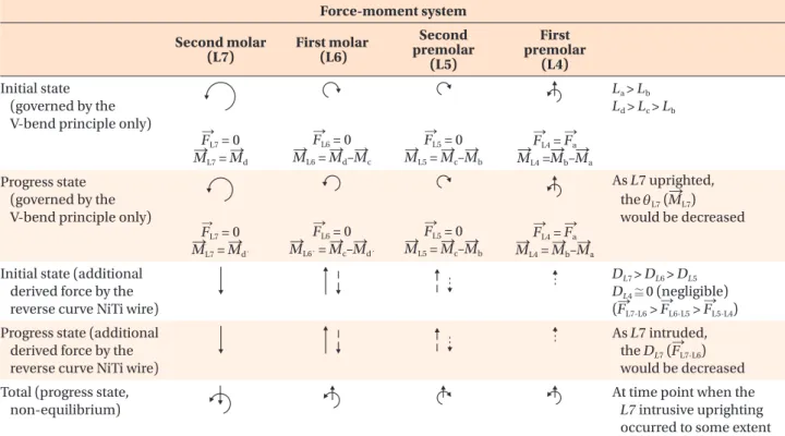
Table 4. The progress of the force-moment system changed by the biocreative reverse curve system (not equilibrium
state) Force-moment system Second molar (L7) First molar (L6) Second premolar (L5) First premolar (L4) Initial state (governed by the
V-bend principle only) → FL7 = 0 → ML7 = →Md → FL6 = 0 → ML6 = →Md–→Mc → FL5 = 0 → ML5 = →Mc–→Mb → FL4 = → Fa → ML4 =→Mb–→Ma La > Lb Ld > Lc > Lb Progress state (governed by the
V-bend principle only) → FL7 = 0 → ML7 = →Md´ → FL6 = 0 → ML6´ = →Mc–→Md´ → FL5 = 0 → ML5 = →Mc–→Mb → FL4 = →Fa → ML4 = →Mb–→Ma As L7 uprighted, the θL7 (→ML7) would be decreased
Initial state (additional derived force by the reverse curve NiTi wire)
DL7 > DL6 > DL5 DL4≅0 (negligible) (→FL7-L6 > → FL6-L5 > → FL5-L4)
Progress state (additional derived force by the reverse curve NiTi wire)
As L7 intruded, the DL7 (F→L7-L6)
would be decreased Total (progress state,
non-equilibrium)
At time point when the L7 intrusive uprighting occurred to some extent NiTi, nickel-titanium; F, force (straight arrows); →→ M, moment (circular arrows); L, interbracket distance; D, vertical distance from the bracket to the reverse curve NiTi wire; θd, angle of insertion of the arch wire at the initial state; θd′, angle of insertion
of the arch wire at the progressed state; Solid straight arrows, action (intrusion) and reaction (extrusion) force between the L7 and L6 (F→L7-L6); Dashed straight arrows, action (intrusion) and reaction (extrusion) force between the L6 and L5 (
→
FL6-L5); Dotted
smaller than the moment on the first molars, the di-rection of the moment on the first molars will switch from clockwise to counterclockwise (in second row of Table 4). This sequential uprighting moment will further propagate toward the anterior teeth in this manner. Ad-ditionally, the vertical distance between the bracket and the reverse curve NiTi arch wire increases exponentially toward the posterior teeth (DL7 > DL6 > DL5 in Table 4 and Figure 5). As a result, according to the law of ac-tion and reacac-tion, an intrusion force is applied to the posterior tooth and an extrusion force is applied to the anterior tooth immediately by the derived force of the reverse curve NiTi arch wire (Table 4).17 The total bal-anced force-moment systems are indicated in the last row of Table 4 after some time period has passed, since the second molar begins to move intrusive uprightingly. Although it is impossible to obtain a definite force and moment in these two couple systems, it does make sense that the teeth will continue to move with this tendency, and if there are no other constraints, the mandibular posterior teeth eventually be aligned with the reverse curve NiTi arch wire based on the shape-driven mechanics.
The overall treatment effects of the BRC system in the mandibular arch are illustrated in Figure 6. One of the noticeable positive effects was its effectiveness in reconstructing the mandibular occlusal plan due to the extrusive distalization of the premolars and the first mo-lars combined with intrusive distalization of the second molars. This is a generally necessary outcome in Class II camouflage treatment, while in Class I cases, it is par-ticularly useful for the treatment of patients with dento-alveolar open bite. The angulation change in the tooth axis was larger in the order of second molars < first mo-lars < second premomo-lars < first premomo-lars. This pattern seems to be associated with the fact that the increase in the inter-bracket-distance toward the distal tooth can
create a larger moment that can further change the an-gulation of the teeth. Another explanation can depend on how the length of the moment arm from the fulcrum point is defined. If the location of the brass wire con-nector is defined as the unchangeable fulcrum point of the reverse curve arch wire, then the second molars will have longest arm that will generate the biggest mo-ment.18
In cases with teeth engaged by the reverse curve arch wire in between the second molars and the I-shaped C-tube miniplate, as observed in all our clinical subjects, some degree of extrusion of these teeth is unavoidable, and the extrusion can be transitional or long-lasting. This is because the moment at the distal terminal of the arch wire will usually be strong enough to exert an im-mediate extrusive force on the anterior teeth when the arch wire terminals are actively engaged into the second molars. Therefore, if the extrusion of any of the poste-rior teeth in front of the second molars is not desired during the leveling of the mandibular curve of Spee, one should consider two options: The first would be not to engage these teeth in the reverse curve arch wire during the second molar distal tipping stage. In other words, the distal tipping moment should be applied on the sec-ond molars only, directly from the I-shaped C-tube mini-plate without any teeth in the middle. The second op-tion would be to reduce the amount of moment on the second molars up to a point where no extrusive force will be generated when the arch wire is engaged on the second molars, even though the amount of distally intrusive tipping of the second molars might not be as dramatic as the results of the current study. The amount of distal tipping moment can be controlled by regulat-ing how high the anterior curvature of the reverse curve is supported by the brass wire connector of the C-tube miniplate at the anterior mandible. The higher and more
Occlusal plane reconstructed L7: Intrusive distal uprighting L6: Distal uprighting L5: Slightly extrusive distal uprighting L4: Slightly extrusive distal uprighting L1: Distal drifting
Figure 6. Overall treatment results of the biocreative reverse curve system (as referenced by the mean value in Table 2).
L1, lower incisor (distalized: 0.48 mm, extruded: 0.44 mm); L4, first premolar (distalized: 0.94 mm, extruded: 0.75 mm, uprighted: 0.63°); L5, second premolar (distalized: 0.59 mm, extruded: 0.58 mm, uprighted: 1.46°); L6, first molar (distal-ized: 1.01 mm, uprighted: 7.29°); L7, second molar (distal(distal-ized: 0.53 mm, intruded: 1.42 mm, uprighted: 10.83°).
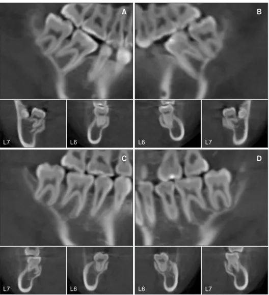
lingually twisted the NiTi arch wire is engaged by the I-shaped C-tube miniplate, the greater the curvature for the distal intrusive moment generated at the distal end of the reverse curve arch wire. In other words, if the BRC system had none of the aforementioned biomechanical restrictions, the mandibular posterior teeth would tip back concurrently along the shape of the reverse curve arch wire. In addition to biomechanical considerations, patient-specific anatomic variations should be care-fully considered when the BRC system is included in the treatment planning. The clinical situation presented in the Results can be a good example for elucidating the importance of evaluating anatomic variations. In the pa-tient whose findings are shown in Figure 7, the distanc-es between the lingual cortical margin to the first and second molars were short. Since the second molars tip distally with intrusive vectors, the distal root can contact the lingual cortical bone, which may interfere with fur-ther intrusion of the second molars. The intrusive vec-tor of the distal tipping moment can then function as
the extrusive vector of the teeth in front of the second molars. Sufficient distance between the lingual cortical margin to the first and second molars ensures enough room for distal and intrusive tipping of the second mo-lars.
Further studies are needed to study various modifica-tions of the BRC system to better control the extrusive movement of the teeth in front of the second molars, especially when the extrusive tooth movement is not wanted. If the mandibular first molars need to be up-righted more than the second molars, the first molars can be the terminal teeth that are engaged in the reverse curve arch wire. In addition, it will be interesting to see the expression of the force system on the teeth when the reverse curve is further twisted lingually to create even bigger amount of intrusive distal tipping moment at the terminal end of the arch wire. Considering these anatomic limitations, tooth movements by the BRC sys-tem in three dimensions might be interesting for evalua-tion in associaevalua-tion with the long-term stability.
A B
C D
L7 L6 L6 L7
L7 L6 L6 L7
Figure 7. Three-dimensional
tooth movement on cone-beam computed tomograms of the case. A, B, Initial state
of the lower right and left molars, respectively (upper: sagittal, lower: frontal view).
C, D, Final state of the lower
right and left molars, respec-tively (upper: sagittal, lower: frontal view).
L6, lower first molar; L7, lower second molar.
CONCLUSION
Based on the findings from the preliminary study, we were able to obtain the following conclusions:
• The null hypothesis was accepted because the change in the movement of the mandibular posterior teeth according to the application of BRC system was verified through this preliminary study.
• The BRC system can effectively tip and intrude the mandibular second molars.
• The occlusal plane is reconstructed counterclockwise by uprighting of the mandibular posterior teeth in the BRC system.
• More studies of the BRC system are warranted to evaluate the dynamic vertical control of the mandibular posterior teeth in relation to patient-specific anatomic conditions.
CONFLICTS OF INTEREST
No potential conflict of interest relevant to this article was reported.
REFERENCES
1. Stern N, Revah A, Becker A. The tilted posterior tooth. Part I: etiology, syndrome, and prevention. J Prosthet Dent 1981;46:404-7.
2. Mohlin B. Prevalence of mandibular dysfunction and relation between malocclusion and mandibular dysfunction in a group of women in Sweden. Eur J Orthod 1983;5:115-23.
3. Roberts WW 3rd, Chacker FM, Burstone CJ. A seg-mental approach to mandibular molar uprighting. Am J Orthod 1982;81:177-84.
4. Simon RL. Rationale and practical technique for uprighting mesially inclined molars. J Prosthet Dent 1984;52:256-9.
5. Capelluto E, Lauweryns I. A simple technique for molar uprighting. J Clin Orthod 1997;31:119-25. 6. Shellhart WC, Oesterle LJ. Uprighting molars
with-out extrusion. J Am Dent Assoc 1999;130:381-5.
7. Zachrisson BU, Bantleon HP. Ask an expert: optimal mechanics for mandibular molar uprighting. World J Orthod 2005;6:80-7.
8. Magkavali-Trikka P, Emmanouilidis G, Papadopoulos MA. Mandibular molar uprighting using orthodontic miniscrew implants: a systematic review. Prog Or-thod 2018;19:1.
9. Ahn HW, Chung KR, Kang SM, Lin L, Nelson G, Kim SH. Correction of dental Class III with posterior open bite by simple biomechanics using an anterior C-tube miniplate. Korean J Orthod 2012;42:270-8. 10. Kim SH, Hwang YS, Ferreira A, Chung KR. Analysis
of temporary skeletal anchorage devices used for en-masse retraction: a preliminary study. Am J Or-thod Dentofacial Orthop 2009;136:268-76.
11. Kojima K, Endo T, Shimooka S. Effects of maxillary second molar extraction on dentofacial morphol-ogy before and after anterior open-bite treatment: a cephalometric study. Odontology 2009;97:43-50. 12. Jee JH, Ahn HW, Seo KW, Kim SH, Kook YA, Chung
KR, et al. En-masse retraction with a preformed nickel-titanium and stainless steel archwire assembly and temporary skeletal anchorage devices without posterior bonding. Korean J Orthod 2014;44:236-45.
13. Ahn HW, Noh MK, Chung KR, Kim SH, Nelson G. Strategic molar uprighting using the biocreative re-verse-curve technique. J Clin Orthod 2020;54:486-94.
14. Burstone CJ, Koenig HA. Creative wire bending--the force system from step and V bends. Am J Orthod Dentofacial Orthop 1988;93:59-67.
15. Lindauer SJ, Isaacson RJ. One-couple orthodontic appliance systems. Semin Orthod 1995;1:12-24. 16. Burstone CJ, Koenig HA. Force systems from an
ideal arch. Am J Orthod 1974;65:270-89.
17. Smith RJ, Burstone CJ. Mechanics of tooth move-ment. Am J Orthod 1984;85:294-307.
18. Isaacson RJ, Lindauer SJ, Davidovitch M. The ground rules for arch wire design. Semin Orthod 1995;1:3-11.