Journal of Magnetics 22(2), 250-256 (2017) https://doi.org/10.4283/JMAG.2017.22.2.250
© 2017 Journal of Magnetics
The Design of a Device for the Generation of a Strong Magnetic Field
in an Air Gap using Permanent Magnets
Václav Žežulka and Pavel Straka*
Institute of Rock Structure and Mechanics v.v.i., Academy of Sciences of the Czech Republic V Holešovičkách 41, 182 09 Prague 8, Czech Republic
(Received 28 November 2016, Received in final form 29 March 2017, Accepted 1 April 2017)
The article presents the principle of a relatively small device that makes it possible to generate a strong magnetic field in an air gap without electrical energy consumption. It describes the implemented design of this device, the method of the assembly of opposing linear arrays from two NdFeB magnet layers, its advantages, the possible ways of increasing the parameters further and its application in various areas.
Keywords : magnetic field, permanent magnets, NdFeB magnets, Halbach arrays
1. Introduction
A great deal of recent research has focused on the use of permanent magnets on the basis of rare earths for the creation of strong magnetic fields [1-7]. The most fre-quently used magnets of the NdFeB type with the maximum energy product of more than 400 kJ/m3 are, however, much more difficult to manipulate with or assemble into arrays than classic ferrite magnets with the (BH)max of approximately 30 kJ/m3. This is caused by rapidly increasing magnetic forces between these magnets and between the magnets and the ferromagnetic objects around them.
In order to prevent the damage of these strong magnets as they are being rapidly attracted to each other, safe methods for the assembly of large magnetic blocks which make it possible to control the speed of attraction have been developed and patented. It is particularly advant-ageous to insert the magnets gradually into a vertical tube filled with a liquid, with the adjacent surfaces of the magnets having the opposite polarity. Through a controll-ed discharge of the liquid from the space between the magnetic plates, one can then control the speed of their attraction and eliminate the possible partial demagneti-zation of the magnets during their assembly.
The mentioned methods have been used for the
assemb-ly of large magnetic blocks from NdFeB magnets, placed first into laboratory and subsequently also into big industrial magnetic filters for the purification of ceramic casting substances and glazes. The high values of mag-netic induction achieved in an air gap in the separation zone (up to approximately 1 T in the air gap of a width of 30 mm in the case of laboratory filters and ca 0.6 T in the air gap of a width of 70 mm in the case of industrial filters) substantially increased the efficiency of the cap-ture of undesirable ferromagnetic admixcap-tures (ferrous abrasions) in comparison with filters with ferrite magnets [8]. When these large magnetic blocks were used in a magnetic separator suspended above conveyor belts, long-term technological tests in a similar comparison also showed a significantly higher efficiency of the capture of ferromagnetic admixtures from raw materials.
A model device enabling the assembly of two opposing linear Halbach arrays with a continuously adjustable di-stance between them has been designed for the generation of strong magnetic fields in an air gap [9]. Assemblies with one-sided magnetic flux – Halbach arrays – have already been the subject of numerous publications, e.g. [10-12]; some of which have been mentioned and described in detail in our previous work [9]. Essentially, the Halbach array is a special arrangement of permanent magnets that augments the magnetic field on one side of the array while cancelling the field to near zero on the other side. This is achieved by having a spatially rotating pattern of magnetization. A computer simulation as well as the actual implementation have confirmed that the use
©The Korean Magnetics Society. All rights reserved. *Corresponding author: Tel: +420 266 009 402 Fax: +420 284 680 105, e-mail: [email protected]
of these opposing linear Halbach arrays with NdFeB magnets makes it possible to achieve (in the defined volume) magnetic fields with magnetic induction values exceeding the level of the remanent magnetization of the permanent magnets used. In the case of the above-men-tioned small device for the assembly of opposing arrays from individual NdFeB magnets, the magnetic induction achieved in a 5-mm-wide air gap was 2.16 T; in the middle of a 30-mm-wide air gap, it was 0.82 T.
Building on previous results, a similar but much bigger device was created. It makes is possible to implement various opposing arrays consisting of large magnetic blocks from NdFeB magnets [13]. The use of these large blocks again in the assembly of opposing Halbach arrays substantially increased the area of the homogeneous field with a higher magnetic induction value in comparison with the previous small device – for instance, the mag-netic induction achieved in the middle of an air gap of the same width of 30 mm was 1.5 T.
2. Theory
For the design of NdFeB magnetic devices, a computer simulation is a widely used method. In our case, the course of magnetic induction in the air gap between two opposing Halbach arrays, i.e. two magnet layers [14], was computed. As a theoretical basis, a computational model was formulated using the scalar magnetic potential Φ and the finite element method according to [15].
In this approach, two types of sub-regions are distin-guished: a source-free medium (air) and permanent nets. As starting relations, the definitions of scalar mag-netic potential and magmag-netic induction were considered and a magnetic induction divergence condition respected. To compute the distribution of magnetic field intensity , this is expressed using the scalar magnetic potential F, defined as:
. (1)
Magnetic induction is defined as:
, (2)
where is magnetization. It is assumed that the mag-netization in the permanent magnets used is homogeneous and the medium, air, is magnetically isotropic. Magnetic induction must satisfy the zero-divergence condition:
. (3)
By inserting the scalar magnetic potential in (2) and combining it with the divergence condition (3), we obtain:
. (4)
Equation (4) constitutes the expression governing a solution of the scalar magnetic potential Φ, while both above-mentioned sub-regions are considered without free currents. Due to this, the tangential components of the magnetic field intensity along their mutual boundaries are continuous. Nevertheless, the continuity of the normal components of magnetic induction must be claimed. Therefore
, (5)
where index 1 is related to the permanent magnet sub-region and index 2 to the adjacent air sub-sub-region. From (5) and definitions (1) and (3), it follows that
, (6)
where is the normal unit vector on the interface boundary printing from sub-region 1 to sub-region 2. Equation (6) is the boundary condition.
Further, equation (4) can be treated as governing the differential equation on the domain:
LΦ = f. (7)
Here, L is the differential operator and f the excitation (or forcing) function. Together with the boundary condition, it defines a boundary-value problem for the scalar mag-netic potential. A solution of this problem has been obtained using the finite element method according to [12] through a variational approach. No direct solution, but a functional minimization on the domain Ω is used. The functional is written as
, (8)
where is an approximate solution to (7). The approxi-mation of a certain solution in the e-th element is express-ed as:
, (9) where n is the number of nodes in the element, Φje is the
scalar magnetic potential at the j-th node, and Nje is the
interpolation function of that node. The next step is the insertion of approximate solutions to (8) and the use of the Galerkin method [16] to select the weighting func-tions as those for the expansion of an approximate solu-tion. The whole minimization procedure leads to the linear equation systems (10):
. (10)
Here, Ke and Be matrices are obtained using (8) for each H H = ∇– Φ B = μ0M + μ0H M ∇B = 0 ∇μ0∇Φ = ∇μ0M n n1B1 − n2B2 = 0 nμ0M + nμ0Φ1) − nμ0Φ2) = 0 n F Φ˜( ) =
∫
Ω (∇μ0∇Ω μ– 0∇M)dΩ = 0 Φ˜ Φ˜e = Σj=1n NjeΦje = N{ }ej T{Φe} = Φ{ e}T{ }Ne Σe 1M= (Ke⋅{Φe}Be) = 0element and {Φe} indicates the column vector of scalar magnetic potential values for nodes of the e-th element. Based on (8), (9) and (10), the course of magnetic induc-tion values in the air gap between two opposing Halbach arrays was computed. According to this simulation, a configuration of NdFeB magnets consisting of two opposing linear Halbach assemblies was implemented and described.
The numerical modeling of the experimental array by FEM was carried out using the ANSYS software package [9]. Each system of Halbach assemblies was represented by appropriate 3D model in order to obtain the magnetic flux distribution in the air gap. The magnetic assemblies were surrounded by a rectangular air region with the infinite elements on its outer boundary to simulate the infinite domain. The geometric dimensions of the men-tioned region were given by the distances from outer model boundaries to the appropriate magnetic assembly surfaces. The distances were chosen as multiples of mag-netic assemblies dimensions in x and z-directions, and y-size plus half-gap thickness in y-direction. The value of the multiple varies from 5 to 7. Such conditions were checked to secure stable results of the computation. From the same reason, the size and the number of the elements in the model was tested as well. It was found that in order to achieve stable results, models had to contain approxi-mately 2 500 000 elements. Further increase of element number does not substantially improve the stability increase, and moreover it leads to the superfluous growth of the computational time.
3. Experiments
3.1. Principle
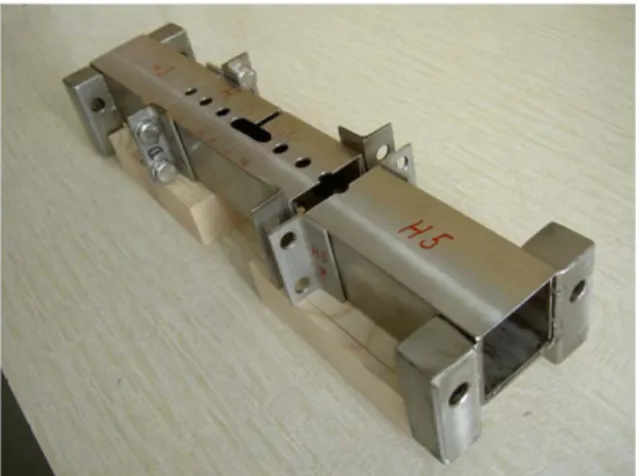
The new apparatus builds on the previous construction design (or preparation) for the assembly of opposing linear arrays from strong permanent magnets [9], where the distance between the arrays can be continuously adjusted. Nevertheless, a disadvantage of this successfully tested apparatus (see Fig. 1) is its relatively big size with respect to the volume of the magnetic field created in the air gap – its pushing mechanisms for pressing the assemblies together and the mechanism for the setting of the distance between the arrays are relatively space-consuming, which significantly limits or entirely prevents some applications of this device.
These drawbacks are eliminated by the new device created through the modification and complementation of the previous design. The improvement lies in the possi-bility to fix each magnet array in its position after it has been drawn together in a tube for example by means of
blocking rods passing across the tube on each side of the array. Similarly, one can fix the mutual position of oppo-sing arrays by inserting spacer parts of the required height, hence with a fixed air gap. This blocking of the arrays makes it possible to loosen and remove both the pushing mechanisms and the mechanism for the setting of the distance, which significantly reduces the overall size of this device.
3.2. Description
The complete, assembled new device, i.e. including the above-mentioned mechanisms for pressing the assemblies together and the mechanism for the setting of the distance, is shown in Fig. 2. It is evident from the comparison with the original design ([9], Fig. 1) that each of the originally solid tubes is divided into three parts – one central and two lateral – which are connected by side angle flanges and screws. The length of each central part of the tube equals the sum of the total length of the magnet array and
Fig. 1. (Color online) The original apparatus for the creation of a strong magnetic field.
Fig. 2. (Color online) The complete new design of the appa-ratus for the creation of a strong magnetic field.
the thickness of two side inner supporting non-magnetic plates, on which threaded pushrods rest when the arrays are drawn together. At both ends of the central part of both tubes in Figs. 2 and 4, one can also see the ends of transverse blocking rods with nuts on them. Each rod passes through the coaxial holes in the walls of the angle flange, in the side walls of the tube and in the support plate. At the bottom part of the tube, there are two spacer parts (hollow rectangular bars with inserted square-section bars) for the setting of the air-gap width, on which the upper tube abuts when the two tubes approach each other. The height of these spacer parts can be selected according to the required air-gap width.
3.3. The method of the assembly of linear opposing arrays from NdFeB magnets
The magnets used for the assembly of the arrays were the same as those in the original device [9]: NdFeB blocks from the material N45 with remanent magnetization Br = 1.354 T and the maximum energy product (BH)max = 348
kJ/m3 were used. The dimensions of Ni-coated blocks were 50 × 50 × 30 mm, preferentially oriented in the direction of the height of 30 mm. Smaller blocks necessary for the completion of the assemblies were cut from these blocks with a diamond blade while being cooled with water, always in such a way as to preserve the preferential orientation.
Before the arrays begin to be assembled, the entire device is disassembled into individual parts, with the lateral parts and the central part of each tube remaining firmly joined by flanges and screws into one whole. The mechanisms for pressing the assemblies together and the mechanism for the setting of the distance are dismantled. Fig. 3 shows the situation from the assembly of the upper tube when its left side part is already firmly attached to
the central part and the right side part is ready to be attached.
The two tubes are then moved away from each other to such a distance that prevents the interaction of magnetic forces. Each array is assembled individually and separately. In the case of the creation of Halbach arrays, it is possible to begin the assembly of the bottom array by placing and setting the central magnet in the middle of the bottom tube. When this or any other magnet is placed in the array, it is necessary to respect their polarity according to [9], Fig. 4. For the visual control of the position of individual magnets and the precise placement of the entire array in the centre, the bodies of both tubes have been provided with holes. In the next step, the lateral magnet and the supporting plate are placed on one side of the bottom tube, complemented by the bottom part of the pushing mechanism (including the vertical guiding angle bars) on this side. The same procedure is then used on the other side of the bottom tube. As the pushscrews of the pulling preparations at the bottom tube are simultaneously tightened on both sides, the side magnets are moved until they touch the central magnet. By loosening one push-screw and tightening another, it is possible to set the entire array of magnets precisely in the centre of the tube. The positions of the transverse holes in the side walls of the flanges, in the tube and in the supporting plates of the magnets must correspond to this position of the array – they must be coaxial on both sides of the magnet array. Subsequently, transverse blocking rods are inserted into these transverse holes from both sides and nuts are screwed onto the rods. In order to increase the safety in the case of a possible improper handling, the nuts can be adequately secured against disassembly.
Separately from the assembled bottom part of the device, but in the same way, it is possible to assemble the
Fig. 3. (Color online) A separate upper tube without auxiliary mechanisms.
Fig. 4. (Color online) A compact device for the creation of a strong magnetic field in an air gap.
top array of the magnets in the upper tube, including the placement of the transverse blocking rods and nuts. The next step is to insert vertical adjusting screws into this part of the device from above and to screw them fully in. The entire assembled upper part of the device with the preset maximum distance between the arrays is then placed between the vertical guiding angle bars of the bottom part and moved towards it until the ends of the adjusting screws touch the transverse parts of the pulling mechanism at the bottom.
In the next stage, by loosening the vertical adjusting screws, the upper tube is gradually moved closer to the fixed bottom tube until it touches the spacer parts of the central part of the bottom tube. Afterwards, it is possible to loosen, on an arbitrary side of the device, two pushscrews that are placed on top of each other in the upper and lower tubes, and remove both lateral parts of the tubes lying above each other including the pulling and setting mechanisms on this side.
After the removal of the lateral sides of the upper and lower tubes on one side of the device, both central parts of the tubes are mutually fixed by a side connecting plate of sufficient rigidity, which is attached to the end, lateral flanges by means of connecting screws with nuts. The procedures for the removal of the lateral parts of the tubes and the subsequent mutual fixing of the central parts of the tubes by a connecting plate on the opposite side are similar.
The resulting compact device for the creation of a strong magnetic field of up to more than 2 T in an air gap (basically an array of the actual opposing central parts of the tubes with inserted arrays from permanent NdFeB magnets alone) is shown in Fig. 4.
4. Results and Discussion
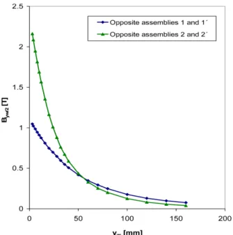
As far as the magnetic induction values achieved in the air gap are concerned, the results for the same magnet arrays correspond to those obtained in the case of the previous device [9], Figs. 5 and 6. As an example for quick orientation, Fig. 5 shows the dependence of mag-netic induction in the middle of an air gap Byw/2 on the width of this gap yw in the case of the simplest
arrange-ment of opposing magnets (the blue curve, diamonds) and in the case of two opposing Halbach arrays (the green curve, triangles), in both cases assembled from individual magnets. The arrangement of these arrays in two views including dimensions is schematically depicted in [9], Figs. 2 and 4.
A comparison of the values of the magnetic induction Byw/2 obtained through the modeling and measurement in
the case of the opposite Halbach arrays from small NdFeB magnets with the arrangement implemented is clear from Fig. 6. [9].This comparison has shown their high corre-lation. In the case of two opposing Halbach arrays, the correlation is within 5 %.
The conformity of results obtained by experiments and
Fig. 5. (Color online) The dependences Byw/2 = f(yw) for two types of opposing assemblies from small NdFeB magnets.
Fig. 6. (Color online) Comparison of the course of the values of the magnetic induction in the middle of an air gap between two opposing linear Halbach assemblies – model and exper-iment [9].
computer simulation has authorized the further procedure, focused on implementing of Halbach opposite assemblies from large magnetic blocks and thus enabling realistically achieve significantly stronger magnetic fields in the air gap between the assemblies. Considering the achieved results, the computer simulations significantly contributed to the continuation of works, focused on the design of the proposed facility for creation of powerful magnetic fields using permanent magnets.
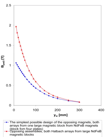
In the case of the bigger device for the creation of a strong magnetic field using large magnetic blocks from NdFeB magnets mentioned in the introduction, it is possible to make a similar adjustment and complemen-tation like in the case of the previous described small model deice for the creation of opposing arrays from small NdFeB magnets. In the entire range, the values of magnetic induction achieved for the new device created in this way would have been again in full agreement with the results given and discussed in Ref. [13], Figs. 7-12. Fig. 7 shows an example of the dependence of magnetic induction in the middle of an air gap Byw/2 on the width of this gap yw in the case of the simplest arrangement of opposing magnets (the blue curve, diamonds) and in the
case of two opposing Halbach arrays (the red curve, triangles), in both cases assembled from large NdFeB magnetic blocks. The arrangement of these arrays in two views including dimensions is schematically depicted in [13], Figs. 1 and 6.
The magnetic field values Byx/2 were obtained by a
quite similar measurement method used both in the case of opposed assemblies of small NdFeB magnets (Fig. 5) and in the case of two types of assemblies from large magnetic blocks of NdFeB magnets (Fig. 7).
The measurements of the magnetic induction in the individual configurations were performed using the same F. W. Bell teslameter, type 5080 with the Hall transverse probe.
When the dependence Byw/2 = f(yw) was measured, the upper array of magnets (the upper tube of the apparatus for the creation of a strong magnetic field) was gradually, step by step, moved closer to the solid bottom array in the bottom tube. For the selected setting of the width of the air gap yw, magnetic induction was measured in the
middle of the width of this gap, always using a solid non-magnetic spacer support/pad under a probe of a height equal to yw/2 minus ½ the thickness of the probe for its
more precise setting.
It is evident that one set of the removed mechanisms for pressing the assemblies together and the mechanism for the setting of the air-gap width can preferably be reused for the creation of other compact devices. The device would then be dismantled in reverse order exclusively by the producer after the mentioned mechanisms are reattached.
Another advantage of the selected solution is that the magnet arrays are assembled without adhesive, which makes it possible to disassemble the arrays without any problems into individual magnets or magnetic blocks; if necessary, these magnetic blocks or plates can be mag-netized again or used in the same or a different device or another array configuration. Considering the current, relatively high price of mainly NdFeB magnets with the maximum energy product, their reuse, especially in the case of large devices, can lead to substantial savings.
5. Conclusions
The device can be used to create strong magnetic fields without electrical energy consumption, for instance in the magnetic separation of raw materials in the case of insufficient electric power supply at the treatment site, in magnetic filters for the purification of various suspensions – e.g. production of ceramics and porcelain, in the food industry etc., further also in instrument technology and
Fig. 7. (Color online) The dependences Byw/2 = f(yw) for two types of opposing assemblies from large magnetic blocks from NdFeB magnets.
quite likely in other areas as well. Nevertheless, a pre-requisite for its application in any industrial facility is the possibility to create a strong magnetic field in a suffici-ently large volume and width of an air gap, which are necessary for the fulfillment of the desired function and parameters of the device. A realistic way to meet this condition is the already-mentioned use of large magnetic blocks, consisting of strong NdFeB magnets. In com-parison with the previously described implementation of small opposing magnet arrays, the use of these large mag-netic blocks makes it possible to generate strong magmag-netic fields in a substantially greater air-gap volume and with a larger air-gap width.
The simplest and practically immediately implemen-table method of the application of the new device is to rotate it by 90° such that the two tubes are not placed above but beside each other. It is then possible to insert in the air gap (or the separation zone) a cassette with a matrix (e.g. from expanded metal or stainless-steel wool), into which the suspension to be purified (e.g. glaze, ceramic casting substance, kaolin etc.) is fed from above. Because of the high magnetic field achieved in the separation zone, the matrix captures not only strongly magnetic impurities (e.g. ferrous abrasions), but, depend-ing on the magnetic-induction value, also weakly mag-netic impurities (e.g. the coloring oxide Fe2O3). After
some time, the feeding into the cassette is stopped, the cassette is removed from the separation zone, the captur-ed magnetic share is rinscaptur-ed with water and the clean cassette is inserted back into the separation zone.
A device based on this principle makes it possible to create an even stronger magnetic field in a comparable air gap than earlier (see the introduction) – e.g. by using stronger magnets with higher maximum energy product,
using larger magnetic blocks or by optimizing the dimen-sional proportions of Halbach arrays etc.
Acknowledgement
This work was carried out thanks to the support of the Long-Term Project for the Conceptual Development of the Research Organization No. RVO 67985891.
References
[1] E. P. Furlani, Academic Press, San Diego, London (2001). [2] J. M. D. Coey, J. Magn. Magn. Mater. 248, 441 (2002). [3] Ch. Li and M. Devine, IEEE Trans. Magn. 41, 10 (2005). [4] A. E. Marble, IEEE Trans. Magn. 44, 5 (2008). [5] J. E. Hilton and S. M. McMurry, J. Magn. Magn. Mater.
324, 2051 (2012).
[6] E.-B. Park, S.-D. Choi, C.-D. Yang, and W.-S. Lee, J. Magn. 3, 69 (1998).
[7] E.-B. Park, S.-D. Choi, and C.-D. Yang, J. Magn. 5, 59 (2000).
[8] V. Žežulka, P. Straka, and P. Mucha, Int. J. Miner. Pro-cess. 78, 31 (2005).
[9] V. Žežulka, J. Pištora, M. Lesňák, P. Straka, D. Ciprian, and J. Foukal, J. Magn. Magn. Mater. 345, 7 (2013). [10] K. Halbach, IEEE Trans. Nucl. Sci. NS-26, 3882 (1979). [11] R. Bjørk, A. Smith, and C. R. H. Bahl, J. Magn. Magn.
Mater. 322, 133 (2010).
[12] R. Bjørk, C. R. H. Bahl, A. Smith, and N. Pryds, IEEE Trans. Magn. 47, 1687 (2011).
[13] V. Žežulka and P. Straka, J. Magn. 21, 3 (2016). [14] J. Choi and J. Yoo, IEEE Trans. Magn. 44, 10 (2008). [15] Jin, J., J. Wiley & Sons Inc., New York (2002). [16] O. C. Zienkiewicz, R. L. Taylor, and J. Z. Zhu, 6th