2354
Copyrightⓒ The Korean Institute of Electrical Engineers
Active Disturbance Rejection Control for Single-Phase PWM Rectifier
with Current Decoupling Control
Ruitao Yan* and Ping Wang
†Abstract – This paper proposed a novel double closed control strategy for single-phase voltage source pulse width modulation (PWM) rectifier based on active disturbance rejection control (ADRC) and dq current decoupling control. First, the mathematical model of the single-phase PWM rectifier in the d-q axis synchronous rotating reference frame is established by constructing a virtual component using a second-order generalized integrator (SOGI). Then, the mathematical model is simplified according to the active power conservation, and the first-order equation of single-phase PWM rectifier voltage outer loop is acquired. A linear auto-disturbance rejection controller is used to design the voltage outer loop according to the first-order equation. Finally, the proposed control strategy and the traditional PI control are compared and verified by simulation and physical experiments. Both simulation and experimental results confirm that the proposed control strategy has excellent dynamic performance and strong rejection ability to disturbances.
Keywords: Single-phase PWM rectifier, Active disturbance rejection control, Current decoupling control, Second-order generalized integrator, Dynamic performance.
1. Introduction
Pulse width modulation (PWM) rectifier has been extensively used in various fields because of it’s advantages including the input sinusoidal current, unity power factor and energy flow in opposite direction. In particular, single-phase PWM rectifier gets more important applications in some specific fields, such as electric vehicle charging and renewable energy grid connected power generation [1-4].
Current control strategy for single-phase PWM rectifier is dominated by direct current control and direct power control, and the direct current control is used more widely. Among direct current control strategies, there are current hysteresis control [5, 6], proportional-integral (PI) and proportional-resonant (PR) based control [7-10], current decoupling control [11-13] and predictive based current control strategies [14-16]. In order to achieve zero steady-state error control of grid-side current, PR control and current decoupling control in synchronous reference frame are usually adopted. The PR approach is simple and easy to implement for single-phase application while achieving zero steady-state error control, but it has several drawbacks, such as sensitivity to small variations in grid-side frequency, exponentially decaying response to step changes and possibility of instability to the phase shift of current sensors.
Current decoupling control has been widely used for both single-phase and three-phase PWM rectifiers
[17-19] because of superior steady-state performance. In the synchronous reference frame, AC variables can be converted into DC variables so that PI regulators can achieve infinite gain at the steady-state operating point and realize a zero steady-state error. This approach can be applied to three-phase PWM rectifier efficiently, but it is needed to create a set of virtual orthogonal variables so as to obtain DC variables by means of rotating coordinate transformation. The virtual orthogonal current component is usually obtained by shifting the measured real signals by a quarter of the fundamental period [20]. Then, the real and shifted current components are regarded as α and β components for coordinate transformation. This approach is relatively simple and straightforward; however, the introduction of such delay in the system tends to deteriorate the dynamic response, which becomes slower and oscillatory. A second order generalized integrator (SOGI) is adopted in order to create the virtual current component, which can realize the 90° phase shifting and filter out high frequency harmonics of input current [21].
Furthermore,current decoupling control of single-phase PWM rectifier has several PI regulators, which seriously affect dynamic performance of the system. And the voltage outer loop usually adopts PI controller or improved PI controller, which is difficult to suppress the output voltage fluctuation of DC side when the load changes or disturbance exists. Active disturbance rejection control (ADRC) proposed by Han [22, 23] is a nonlinear controller composed of nonlinear tracking differentiator (TD), extended state observer (ESO) and nonlinear state error feedback (NLSEF) for an uncertain system. The ESO can automatically estimate and compensate all kinds of
† Corresponding Author: Dept. of Electrical Engineering, Tianjin University, China. ([email protected])
* Dept. of Electrical Engineering, Tianjin University, China. ([email protected])
external disturbances in the operation and parameter variations of the system, and don’t need the accurate model. So, the ADRC has strong robustness and rejection ability to disturbance [24, 25].
This paper focuses on the improvement of control dynamic performance of single-phase PWM rectifier, and proposes a novel control strategy based on ADRC and current decoupling control. The voltage outer loop adopts the first-order linear ADRC instead of the traditional PI controller, and the current loop adopts dq current decoupling control which adopts the SOGI to construct the virtual component. The proposed control strategy has excellent dynamic response and rejection ability to disturbance while realizing zero steady-state error control. Finally, simulation and experimental results confirm the superiority of proposed control strategy in dynamic performance and disturbance rejection.
2. Mathematical Model of Single-Phase PWM Rectifier
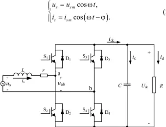
The topology structure of single-phase voltage source PWM rectifier is shown in Fig. 1. S1 ~ S4 are four electrical switching devices of H-bridge, us and is are input AC voltage and current of line side, L and r are boost inductor and equivalent resistance in AC side, uab is input voltage of H-bridge, C and R are filter capacitor and load resistance in DC side, Udc and idc are output DC voltage and current.
As shown in Fig. 1, the dynamics of the AC side of such a system can be described as:
. s s s a b di u ri L u dt = + + (1)
Assuming that the frequency of the network side voltage is ω, the amplitude is usm and the amplitude of the network side current is ism, then the voltage and current in the network side can be described as:
(
)
cos , cos . s s m s s m u u t i i t = w ìï í = w - j ïî (2)where φ represents the lagging phase angle of the network side current to the voltage.
In order to transform (1) to a stationary αβ frame, this paper adopts the SOGI to construct the virtual component. The constructed virtual voltage and current components can be described as:
cos , sin . s s s m s s m u u u t u u t a b = = w ìï í = w ïî (3)
(
)
(
)
cos , sin . s s s m s s m i i i t i i t a b = = w - j ìï í = w - j ïî (4)Transforming (1) to the stationary α-β frame, the following equation is obtained:
. s s s ab di u ri L u dt ab ab = ab+ + ab (5)
A stationary-to-synchronous transformation of voltage and current can be described as:
, . j t sdq s j t sdq s u u e i i e - w ab - w ab = ìï í = ïî (6)
Applying the stationary-to-synchronous transformation to (5) , the mathematical model of single-phase PWM rectifier in d-q rotating coordinate frame is presented:
, . sd abd sd sd sq sq abq sq sq sd di u u ri L Li dt di u u ri L Li dt ì = - - + w ïï í ï = - - - w ïî (7)
3. Proposed Control Strategy Based on ADRC and SOGI
3.1 Current loop controller
As mentioned before, the SOGI is adopted to generate the virtual orthogonal component in this paper. The basic structure diagram of the SOGI is shown in Fig. 2, in which
ω is the fundamental angular frequency and k is the
damping factor. S1 D1 S2 S3 S4 us is id ic L r D2 D3 D4 + -uab + -a b idc C Udc R +
-Fig. 1. Topology of single-phase PWM rectifier
k 1/s 1/s ω2 i' qi' SOIG ɛi kɛi i
According to Fig. 2, the transfer function of SOGI unit can be described as:
' 2 2 (s) . i i s ke =s + w (8) ' 2 2 2 (s) . i qi k s w = e + w (9)
Obviously, the corresponding functions of (8) and (9) are cos(ωt) and sin(ωt) in time domain, which are 90 degrees out of phase. So the orthogonal coordinate system can be constructed. Since the whole control system has s domain model of sinusoidal signal which frequency is ω, it can realize the zero steady-state tracking error of sinusoidal signal with the corresponding frequency. As shown in Fig. 2, the transfer function of the system are:
' 2 2 (s) , i ks i =s + + wks (10) ' 2 2 (s) . qi k i s ks w = + + w (11)
Applying (10) and (11) to the input AC current is, the virtual orthogonal component can be obtained:
(
)
(
)
' ' cos , sin . s s m s s m i i i t i qi i t a b = = w - j ìï í = - = w - j ïî (12)It should be noted that when the resonant frequency of the SOGI is not equal to the line frequency, the tracking error of the SOGI output signals occurs. Therefore, the frequency obtained from the phase-locked loop can be used as the resonance frequency of the SOGI.
Then, variables in d-q rotating coordinate frame can be obtained according to (6) and the governing equation of current decoupling control based on PI controllers is obtained according to (7): * * * * ( )( ) , ( )( ) . d i abd sd dp sd sd sq p i abq sq qp sq sq sd K u u K i i Li s K u u K i i Li s ì = - + - + w ïï í ï = - + - - w ïî (13)
in which r has been ignored because the resistance is too small.
According to (13), the structural diagram of current decoupling control strategy based on PI controllers is shown in Fig. 3.
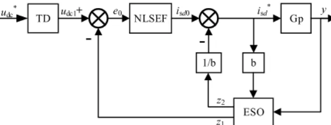
3.2 ADRC design for single-phase PWM rectifier Active disturbance rejection control (ADRC) is a nonlinear controller composed of nonlinear tracking differentiator (TD), extended state observer (ESO) and
nonlinear state error feedback (NLSEF) as shown in Fig. 4. In Fig. 4, TD is used to arrange the transition process making the corresponding output track the input signal smoothly without overshoot in a finite time. ESO can realize real-time tracking of the system, and observe and compensate the time-varying parametric uncertainties and disturbances of the system. NLSEF can realize a nonlinear combination of the state error observed by ESO and output a control variable of the controlled plant.
For most single-output systems, their mathematical models can be simplified as:
( )
(
( )( )
)
( )
( )
1 , , , , , , . n n x f x x x w t t bu t y x t -ì = + ï í = ïî & L (14) where x(n) are system’s state variables of different order,w(t) are system’s disturbances, u(t) is the control output
quantity, b>0 is a controller parameter introduced, y is the measurement output of the system. ADRC can observe and compensate the disturbances of the system, which can make a nonlinear system a integral series system as:
( )
( )
, . n x bu y x t = ìï í = ïî (15)In order to introduce ADRC into the voltage outer loop of single-phase PWM rectifier, the relation between the output voltage udc and the input current isd should be derived as (14).
Suppose the single-phase PWM rectifier is an ideal system. The mathematical expression of input power and
× PI ωL ωL αβ/dq SOGI isα isβ usd isd isq isq* uabq is × PI isd* × × usq uabd
Fig. 3. Structure diagram of dq current controller
udc* +
-e0 Gp ESO 1/b b z1 z2 isd0 isd* y -TD udc1 NLSEFoutput power can be described as: .
ac dc
P =P (16)
Usually, we expect no fluctuation in DC side voltage and different topology and control metheds are proposed to reduce voltage fluctuations as much as possible [26-28]. This paper uses traditional electrolytic capacitor in DC side, which leads to the fluctuation of DC voltage. When the current inner loop adopts decoupling current control, the active power of AC side and the output power of DC side can be expressed as:
2 1 1 . 2 2 . ac sd sd sq sq dc dc dc dc dc dc P u i u i du u P u i u C dt R ì = + ïï í ï = = + ïî (17)
Substituting (17) into (16), the following expression is obtained: 2 2 2 . sq sq dc dc sd sd u i du u u i dt = - RC + C + C (18)
When the rectifier run on the operation of unity power factor, there are usd=usm, usq=0, and substitute x1 for udc2. The following equation is obtained:
1 2 1 u ism sd.
dx x
dt = -RC+ C (19)
It can be seen from (19) that the relation between udc and isd is a first-order equation. Then the voltage outer loop can be designed according to the first order ADRC.
This paper adopts linear ADRC instead of nonlinear ADRC in order to simplify the parameters tuning while still having good control performance. The algorithm of each part of the first-order linear ADRC is shown as follows:
3.2.1 Linear tracking differentiator:
TD arranges the transition process that can make the corresponding output track the input signal smoothly without overshoot in a finite time. The linear TD form is shown as follows [29]:
(
)
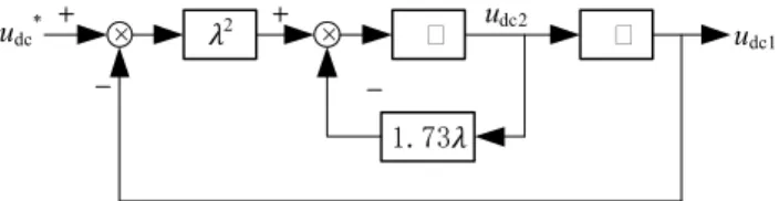
1 2 2 * 2 2 1 , 1.73 . dc dc dc dc dc dc u u u u u u = ìï í = - l - l -ïî & & (20)where udc1 is the arranged transition process tracking the given DC voltage udc*, udc2 is the derivative of udc1, and is the adjustable parameter that decides the transition process speed.
The track speed would be faster if is bigger. But at the same time, it will increase the overshoot. An ideal value of
can be obtained by repeated simulation and debugging. The structural diagram of the TD block is shown in Fig. 5. 3.2.2 Linear extended state observer:
The heart of ADRC is ESO, which can realize real-time tracking of the system disturbances and compensate disturbances in the control variable so as to realize the linearization. Reference [30] offered the method of construct first order linear ESO (LESO) and its algorithm is as follows: 1 1 2 1 2 2 , , . e z y z z e bu z e = -ì ï = -b + í ï = -b î & & (21)
where e is the systematic error, y is the measurement output of the system, z1 is the corresponding estimation of y,z2 is the estimation of total disturbances of the system, b>0 is a controller parameter introduced, u is the control output quantity, β1 and β2 are the adjustable parameters for the systematic error e.
In this application, y is the output DC voltage udcand u is the output of external voltage loop isd*. Therefore (21) can be rewrote as:
1 1 2 1 2 2 , , . dc sd e z u z z e bi z e = -ì ï = -b + í ï = -b î & & (22)
The control parameter β1 and β2 can be adjusted
according to the bandwidth of ESO ω0, and the following
equation can be obtained [31]:
1 0 2 2 0 2 , . b = w ì íb = w î (23)
where larger ω0 can improve the performance of ESO, but
it will also magnify the system noise. So, a compromise is made between the speed at which the observer tracks the states and its sensitivity to the sensor noises in practice.
The structural diagram of the LESO block is shown in Fig. 6.
3.2.3 Linear state error feedback control:
NLSEF is the nonlinear combination of the error between the output of TD and the state variable estimation.
× 2 ʃ
udc* × ʃ
1.73
udc1
udc2
Its output and the total amount of disturbance com-pensation of ESO compose the Control quantity. The linear state error feedback control (LSEF) is shown as follows:
(
)
0 1 1 * 0 2 , . sd p dc sd sd i k u z i i z b = -ìï í = -ïî (24)where kp is the adjustable parameter, and isd* is the d-axis current setting value.
The adjustable parameter can be set according to the bandwidth of the feedback system ωc as:
p c
k = w (25)
where ωc=1/5~1/3ω0 .
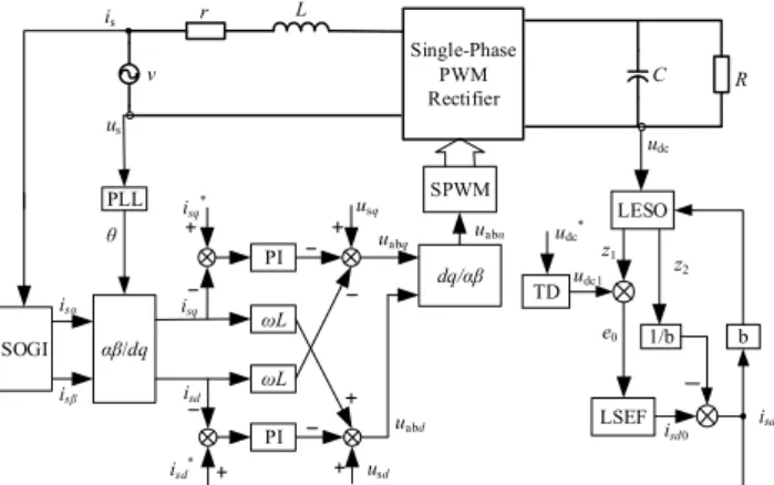
A novel double closed control strategy for single-phase PWM rectifier based on ADRC and dq current decoupling control is proposed according to the above content. The voltage outer loop adopts the first-order linear ADRC and the current loop adopts dq current decoupling control which adopts the SOGI to construct the virtual component. The control block diagram is shown in Fig. 7.
3.3 Control system design
Due to the symmetry of the two current inner loop, the design of the current regulator is discussed with the id control as an example. Considering the delay of the signal sampling and the small inertia characteristic of the PWM control, the structure of current inner loop is shown in Fig. 8.
Kdp+Kdi/s
isd* 1/(τss+1) KPWM 1/(r+Ls) isd usd
Fig. 8. Controlling structure of current inner loop
Kdp+Kdi/s
isd* 1/(τss+1) 1/(r+Ls) isd
Fig. 9. Simplified model of current inner loop In Fig. 8, τs is the sampling period, Ts is the PWM switching period, Kpwm is the transfer function of H bridge.
Usually, 1 0.5 1 pwm s K T s =
+ . In order to simplify the
analysis, the disturbance of usd is not considered, and the simplified model of current inner loop is obtained as shown in Fig. 9.
The open loop transfer function of the current inner loop shown in Fig. 9 is:
( )
s ( 1) ( 1)( 1) dp di di oi K K s r K G s L s s s r + = t + + (26)where take Kdp/Kdi=L/r and (26) turns into:
( )
s ( 1) di oi K G s r s s = t + (27)The current controller is designed according to the typical type I system which the damping ratio of the system ζ is 0.707. The calculation formula of PI controller parameters of current inner loop is obtained as:
, 2 . 2 dp s di s L K = r K = ì ïï t í ï t ïî (28)
Then, the closed loop transfer function of the current inner loop can be obtained:
( )
1 2 1 2 2 ci s s G s s = + t + t (29)At high operating switching frequency, τs is small enough and we can assume that a closed current loop transfer function will be equal to:
( )
1 1 2 ci s G s s = + t (30) × β1 udc × ʃ z1 b*isd* β2 ʃ e z2Fig. 6. Structure diagram of LESO block
PI ωL ωL αβ/dq SOGI isα isβ usd isd isq isq* uabq is PI isd* usq dq/αβ uabd v L Single-Phase PWM Rectifier C r R PLL us θ udc* e0 LESO 1/b b z1 z2 isd0 isd * TD LSEF udc1 SPWM udc uabα
1/(τss+1)
udc* Gp(s) Gci(s) 1/Cs udc
Fig. 10. Controlling structure of voltage outer loop
×
Kp(s+ω0)2 bs(s+2ω0)×
UsdR/2 RCs/2+1 ω02 b(s+2ω0)i
sd*u
dc1Fig. 11. Block diagram of the LADRC
Similar to the current inner loop, the structure of voltage outer loop is shown as Fig. 10.
In Fig. 10, Gp(s) represents the controller of voltage outer loop. When the voltage loop adopts the PI controller, the open loop transfer function of the voltage loop is:
( )
_PI 3 2 s 3 vp vi cv vp vi K s K G s Cs Cs K s K + = t + + + (31)The controller is designed according to the typical type II system and the calculation formula of PI controller parameters is obtained as:
, 5 . 75 vp s vi 2 s C K = C K = ì ï t ï í ï ï t î (32)
As mentioned above, a LADRC is adopted as voltage loop controller instead of PI controller. The block diagram of the LADRC in this system is shown in Fig. 11 [29].
According to Fig. 11, the closed loop transfer function of the LADRC is:
( )
2 0 3 2 0 1 2 3 ( ) 2 sm p LADRC u R k s G s a s a s a s a + w = + + + (33) where 0 2 RC a = b, 1 0 2 sm p u R a =RCbw + k + , b 2 2 2 0 sm2 0 sm p 0 u R a = w +b w +u Rk w , 2 3 sm2 0 p u R a = w k .The structure of voltage loop can be simplified as shown in Fig. 12 when Ts is small enough.
Then, the closed loop transfer function of the system can be obtained:
( )
_ ( )(1/ ) 1 ( )(1/ ) LADRC cv LADRC LADRC G s Cs G s G s Cs = + (34) GLADRC(s) 1/Cs udc* udcFig. 12. Simplified model of voltage outer loop Table 1. Parameters of the system
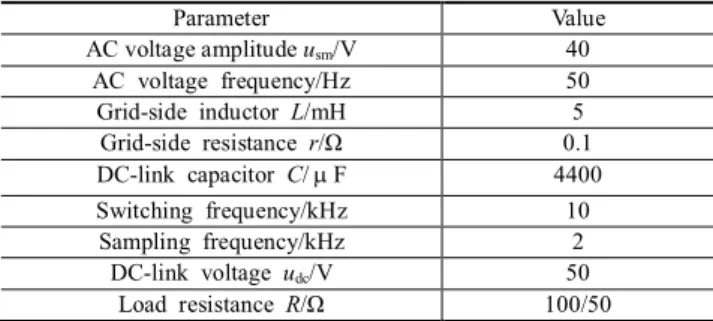
Parameter Value AC voltage amplitude usm/V 40 AC voltage frequency/Hz 50 Grid-side inductor L/mH 5 Grid-side resistance r/Ω 0.1 DC-link capacitor C/mF 4400 Switching frequency/kHz 10 Sampling frequency/kHz 2 DC-link voltage udc/V 50 Load resistance R/Ω 100/50
Table 2. Controller parameters of the system
Parameter Value Parameter Value
l 100 Kdp 5 β1 200 Kdi 100 β2 10000 Kvp_1 2 b 50 Kvi_1 200 ω0 100 Kvp_2 1 kp 30 Kvi_2 100 Ts 0.0001 Kvp_3 2 Kvi_3 300
4. Simulation and Experimental Validation To evaluate the correctness and effectiveness of the proposed control strategy, simulation and experimental study of LADRC and PI controller with 3 different parameters are carried out. The circuit and controller system parameters are shown in Table 1 and Table 2.
The closed loop poles of the system are all located in the left-half plane, which can be solved from Eq. (34). So the closed loop system is stable.
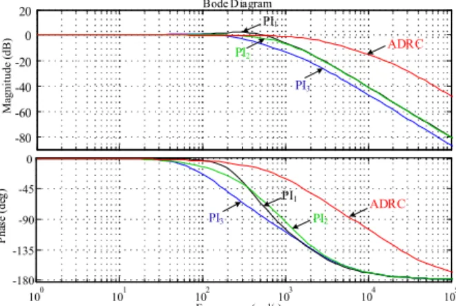
The bode diagram of the closed loop system with PI controller and ADRC controller are shown in Fig. 13. It can be seen from Fig. 13 that the bandwidth using ADRC controller is wider than that using PI controller, which indicate the ADRC has better dynamic response and shorter rise time.
4.1 Simulation results
Simulation comparisons have been carried out in MATLAB/simulink according to the control scheme as shown in Fig. 7. Fig. 14 shows the simulation results of the start-up and load switching from 100Ω to 50Ω stage and Fig. 15 is local enlarged drawing of load switching stage. Fig. 16 is the results of DC-link voltage reference from 50V to 60V. Fig. 17 is the simulation waveform of AC voltage and current at steady state.
Bode Diagram Frequency (rad/s) 100 101 102 103 104 105 -180 -135 -90 -45 0 P ha se ( de g) -80 -60 -40 -20 0 20 M ag ni tu de ( dB ) ADRC PI1 PI2 PI3 ADRC PI1 PI2 PI3
Fig. 13. Bode diagram of the closed loop system
Bode Diagram Frequency (rad/s) 100 101 102 103 104 105 -180 -135 -90 -45 0 P ha se ( de g) -80 -60 -40 -20 0 20 M ag ni tu de ( dB ) ADRC PI1 PI2 PI3 ADRC PI1 PI2 PI3
Fig. 14. Bode diagram of the closed loop system
0.6 0.7 0.8 0.9 1 1.1 1.2 1.3 1.4 1.5 1.6 40 42 44 46 48 50 52 ADRC PI1 PI2 PI3 udc /V t/s
Fig. 15. DC voltage waveform of load variation It can be seen from the Fig. 14 and Fig. 15 that the DC-link voltage can reach steady state quickly without overshooting with ADRC, and the DC-link voltage is more stable and has better disturbance rejection ability. Rectifier with PI control has large overshoot and long response time. This is the same to DC-link voltage reference changing as we can see from Fig. 16.
Besides, Fig. 17 shows that the input AC voltage and current is in the same phase, which means the proposed control strategy achieve unit power factor operation. Simulation results verify that the proposed control strategy
has better dynamic performance and strong rejection ability to disturbances.
4.2 Experimental results
To verify the feasibility and effectiveness of the proposed control strategy further, this paper builds a single-phase PWM rectifier experimental platform based on TMS320F28335 digital signal processor (DSP) as shown in Fig. 18.
Using the proposed control strategy in this paper, the AC voltage and AC current waveforms in the steady state are shown in Fig. 19, and Fig. 20 are DC-link voltage and AC current waveforms of the rectifier at steady state. It can be
0.6 0.8 1 1.2 1.4 1.6 1.8 40 45 50 55 60 65 ADRC PI1 PI2 PI3 t/s udc /V
Fig. 16. DC voltage waveform of voltage reference variation
0.5 0.52 0.54 0.56 0.58 0.6 -50 -40 -30 -20 -10 0 10 20 30 40 50 -5 -4 -3 -2 -1 0 1 2 3 4 5 us /V is /A t/s is us
Fig. 17. AC voltage and current waveforms of steady state
Fig. 18. Experimental platform of single-phase PWM rectifier
seen from Fig. 19 and Fig. 20 that the proposed control strategy can obtain ideal current waveforms and the rectifier can achieve unit power factor operation. Besides, the DC-link voltage can be controlled at a stable value while having frequency doubling fluctuation.
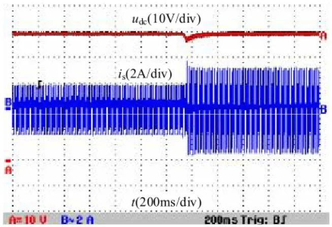
Fig. 21 and Fig. 22 are experimental waveforms of DC-link voltage and AC current when load changed from 100Ω to 50Ω with traditional PI control and linear ADRC
control proposed in this paper. It can be seen from Fig. 21 and Fig. 22 that the DC-link voltage has smaller voltage drop and faster recovery speed with linear ADRC in outer voltage loop compared with traditional PI control. The performance comparison for two control strategies is shown in Table 3. The comparison shows that two control strategies are almost the same in THD, power factor and DC voltage ripple. However, it is also obvious that the proposed control strategy has faster recovery time and smaller voltage drop than that of the control strategy in [32]. The comparison shows that the proposed control strategy with linear ADRC can improve the dynamic and disturbance rejection performance without influence on steady state performance of the single-phase PWM rectifier.
5. Conclusion
This paper proposes a novel control strategy for single-phase PWM rectifier, where the voltage outer loop adopts LADRC instead of traditional PI controller and the current loop adopts dq current decoupling control. The mathematical model of single-phase PWM rectifier in d-q rotating frame is presented which adopts SOGI to construct the virtual component. The design and parameter selection of LADRC block is given according to previous research, which can be improved and optimized in future studies. Moreover, the control system design is also presented in this paper. Simulation and experimental results show that the proposed control strategy has better performance in dynamic response and disturbance rejection without influence on steady state performance.
us(20V/div)
is(5A/div)
t(10ms/div)
Fig. 19. Experimental waveforms of AC voltage and AC current
is(5A/div)
udc(10V/div)
t(4ms/div)
Fig. 20. Experimental waveforms of DC-link voltage and AC current
udc(10V/div)
is(2A/div)
t(200ms/div)
Fig. 21. Experimental waveforms of DC-link voltage and AC current with PI control when load changed
udc(10V/div)
is(2A/div)
t(200ms/div)
Fig. 22. Experimental waveforms of DC-link voltage and AC current with ADRC when load changed Table 3. Performance comparison for two control strategies
Performance ADRC+DQ PI+DQ
AC current THD/% 3.78 3.83
Input power factor 0.998 0.998
DC voltage ripple/% 2.0 2.1
DC voltage drop/V 3 6
Acknowledgements
This work was supported by the National Key Research and Development Program of China (No.2016YFB0900200).
References
[1] G. C. Konstantopoulos, and Q.-C. Zhong, “Nonlinear Control of Single-Phase PWM Rectifiers with Inherent Current-Limiting Capability,” IEEE Access, vol. 4, pp. 3578-3590, 2016.
[2] Kim, Seonghye, and F. S. Kang, “Multifunctional Onboard Battery Charger for Plug-in Electric Vehicles,” IEEE Trans. Ind. Electron., vol. 62, no. 6, pp. 3460-3472, 2015.
[3] C. Meza, D. Biel, D. Jeltsema, and J. M. A. Scherpen, “Lyapunov-Based Control Scheme for Single-Phase Grid-Connected PV Central Inverters,” IEEE Trans.
Control Syst. Technol., vol. 20, no. 2, pp. 520-529, 2012.
[4] H. G. Jeong, J. H. Lee, and K. B. Lee, “A 2nd Order Harmonic Compensation Method for Wind Power System Using a PR Controller, J. Electr. Eng. Technol., vol. 8, no. 3, pp. 507-515, 2013.
[5] P. A. Dahono, “New hysteresis current controller for single-phase full-bridge inverters, IET Power Electron., vol. 2, no. 5, pp. 585-594, 2009.
[6] Ichikawa, Ryota, H. Funato, and K. Nemoto, “Experimental verification of single phase utility interface inverter based on digital hysteresis current controller, Int. Conf. Electrical Machines and Systems
IEEE, pp. 1-6, 2011.
[7] Brenna, Morris, F. Foiadelli, and D. Zaninelli, “New Stability Analysis for Tuning PI Controller of Power Converters in Railway Application, IEEE Trans. Ind.
Electron., vol. 58, no. 2, pp. 533-543, 2011.
[8] D. N. Zmood, and D. G. Holmes, “Stationary frame current regulation of PWM inverters with zero steady-state error, IEEE Trans. Power Electron., vol. 18, no. 3, pp. 814-822, 2003.
[9] R.Teodorescu, F. Blaabjerg, M. Liserre, and P. C. Loh, “Proportional-resonant controllers and filters for grid-connected voltage-source converters, IEE Proc.-Elect.
Power Appl., vol. 153, no. 5, pp. 750-762, 2006.
[10] S. Somkun, and V. Chunkag, “Unified unbalanced synchronous reference frame current control for single-phase grid-connected voltage-source converters,”
IEEE Trans. Ind. Electron., vol. 63, no. 9, pp.
5425-5436, 2016.
[11] R. Zhang, M.Cardinal, P. Szczesny, and M. Dame, “A grid simulator with control of single-phase power converters in D-Q rotating frame, in Proc. 33rd Annu.
IEEE PESC, vol. 3, pp. 1431-1436, 2002.
[12] B. Bahrani, A. Rufer, S. Kenzelmann, and L. A. C. Lopes, “Vector Control of Single-Phase Voltage-Source Converters Based on Fictive-Axis Emulation,
IEEE Trans. Industry Applications, vol. 47, no. 2, pp.
831-840, 2011.
[13] R. Coteli, H. Acikgoz, F. Ucar, and B. Dandil, “Design and implementation of Type-2 fuzzy neural system controller for PWM rectifiers,” International
Journal of Hydrogen Energy, vol. 42, no. 32, pp.
20759-20771, 2017.
[14] J. Rodriguez, J. Pontt, C. A. Silva, P. Correa, P. Lezana, and P. Cortes, “Predictive current control of a voltage source inverter, IEEE Trans. Ind. Electron., vol. 54, no. 1, pp. 495-503, 2006.
[15] W. S. Song, and Z. X. Deng, “Model predictive power control scheme for single-phase PWM rectifiers with constant switching frequency, Electric Machines
and Control, vol. 20, no. 4, pp. 93-100, 2016.
[16] M. P. Akter, S. Mekhilef, N. M. L. Tan, and H. Akagi, “Model predictive control of bidirectional ac-dc converter for energy storage system, J. Electr. Eng.
Technol., vol. 10, no. 1, pp. 165-175, 2015.
[17] Q. Yuan, and K. Xia, “Current Decoupling Control for the Three-level PWM Rectifier with a Low Switching Frequency,” J. Electr. Eng. Technol., vol. 10, no. 1, pp. 280-287, 2015.
[18] H. Acikgoz, R. Coteli, M. Ustundag, and B. Dandil, “Robust Control of Current Controlled PWM Rectifiers Using Type-2 Fuzzy Neural Networks for Unity Power Factor Operation,” J. Electr. Eng.
Technol., vol. 13, no. 2, pp. 822-828, 2018.
[19] O. Kececioglu, H. Acikgoz, C. Yildiz, G. Ahmet, and S. Mustafa, “Power Quality Improvement Using Hybrid Passive Filter Configuration for Wind Energy Systems,” J. Electr. Eng. Technol., vol. 12, no. 1, pp. 207-261, 2017.
[20] M. Gonzalez, V. Cardenas, and F. Pazos, “DQ transformation development for single-phase systems to compensate harmonic distortion and reactive power, IEEE Int. Power Electronics Congress, pp. 177-182, 2004.
[21] M. Ciobotaru, R. Teodorescu, and F. Blaabjerg, “A New Single-Phase PLL Structure Based on Second Order Generalized Integrator, IEEE Power Electron.
Specialists Conf., pp. 1-6, 2006.
[22] Han, Jingqing, “Auto-disturbances-rejection Controller and Its Applications, Control and Decision, vol. 13, no. 1, pp. 19-23, 1998.
[23] Han, Jingqing, “From PID to Active Disturbance Rejection Control, IEEE Trans. Ind. Electron., vol. 56, no. 3, pp. 900-906, 2009.
[24] G. Zhang, Z. Liu, S. Yao, Y. Liao, and X. Chuan, “Suppression of low-frequency oscillation in traction network of high-speed railway based on auto-disturb-ance rejection control,” IEEE Trans. Trans.
Elec-trification Electron., vol. 2, no. 2, pp. 244-255, 2016.
[25] Z. Song, Y. Tian, Z. Yan, and Z. Chen, “Direct Power Control for Three-Phase Two-Level Voltage-Source Rectifiers Based on Extended-State Observation,”
IEEE Trans. Ind. Electron., vol. 63, no. 7, pp.
4593-4603, 2016.
[26] M. S. Irfan, A. Ahmed, J.-H. Park, and C. Seo, “Current-sensorless power-decoupling phase-shift dual-half-bridge converter for dc-ac power con-version systems without electrolytic capacitor,” IEEE
Trans. Power Electron., vol. 32, no. 5, pp. 3610-3622,
2017.
[27] S. Qin, Y. Lei, C. Barth, W. C. Liu, and R. C. N. Pilawa-Podgurski, “A high power density series-stacked energy buffer for power pulsation decoupling in single-phase converters,” IEEE Trans. Power
Electron., vol. 32, no. 6, pp. 4905-4924, 2017.
[28] S. Li, W. Qi, S. C. Tan, and S. Y. R. Hui, “Enhanced automatic-power-decoupling control method for single-phase ac-to-dc converters,” IEEE Trans. Power
Electron., vol. 33, no. 2, pp. 1816-1828, 2018.
[29] L. Shao, X. Liao, “Active disturbancerejection con-troller for PWM rectifier,” Trans. of Beijing Inst. of
Technol., vol. 28, no. 1, pp. 50-53, 2008.
[30] R. Yang, M. Sun, and Z. Chen, “Active disturbance rejection control on first-order plant, J. Syst. Eng.
and Electron., vol. 22, no. 1, pp. 95-102, 2011.
[31] Q. Shi, G. Wang, L. Fu, Y. Liu, Y. Wu, and L. Xu, “Virtual inertia control of d-pmsg based on the principle of active disturbance rejection control,” J.
Electr. Eng. Technol., vol. 10, no. 5, pp. 1969-1982,
2015.
[32] C. Chunkag, and P. Thounthong, “Control of single-phase AC-DC converterer for hybrid microgrid,”
IEEE International Conference on Power Electronics and Drive Systems, pp. 668-673, 2013.
Ruitao Yan He received his B.S. in Electrical Engineering from the China University of Mining and Technology, China in 2012. He is pursuing M.S. in Electrical Engineering from the Tianjin University, China since 2012. His current research interests include PWM converters and intelligent control. Ping Wang She was born in Tianjin, China, in 1959. She received the B.S., M.S., and Ph.D. degrees in electrical engineering from the Tianjin Univer-sity, Tianjin, China, in 1981, 1991, and 2005, respectively. In 1981, she joined Tianjin University as a Teacher and a Researcher, where she is currently a Professor. Her current research interests include power electronic control of renewable energy sources, PWM converters, and intelligent detection and control.