1. INTRODUCTION
This article describes the preparation procedure of the final camera-read It is well known that induction motors dominate the field of electromechanical energy conversion. These machines find a wide role in most industries in particular in the electric utility industry as auxiliary drives in central power plants of power system, as well as a restrictive role in low MVA power supply systems as induction generators, mining industries, petrochemical industries, as well as aerospace and military equipment. Therefore, assessment of the running conditions and reliability of these drive systems is crucial to avoid unexpected and catastrophic failures. Consequently, the issue of the preventive maintenance and noninvasive diagnosis of the condition of the induction motor drives is of great concern, and is becoming increasingly important [1-3]. Motor reliability studies [4] specifically apply to machine, 100Hp or more, that are operated in industrial and commercial installations, The results of these studies show that bearing problems account for over 40% of all machine failures. Over the past several decades, rolling-element (ball or roller) bearings have been utilized in many electric machines while sleeve (fluid film) bearings are installed in only the largest industrial machines. In the case of induction motors, rolling element bearings are overwhelmingly used to provide rotor support. Lubricant contamination and lubricant loss are the most common causes of bearing failures. Other common causes of bearing failures include excessive loading, corrosive environments, and misapplication. Most of these failures start small then propagate or expand, causing the whole machine to breakdown eventually. Vibration monitoring is a reliable tool for bearing failures. The vibration data typically contain
fault signatures and salient fault features because of direct measurement of the critical signal and placement of the vibration sensor. However, placing a sensing device on the motor might not be possible or practical in many applications, especially for a facility that employs a large number of electric machines. The stator current, on the other hand, is readily available in many applications, and is usually measured for motor protection. Therefore, current-based fault detection has become an attractive area for bearing condition monitoring. The main disadvantage of using the current for bearing condition monitoring is the difficulty of distinguishing bearing fault signatures from non-fault components or noise in the stator current. Fault detection based on motor current relies on interpretation of frequency components in the current spectrum that are related to rotor or bearing a symmetries. However, the current spectrum is influenced by many factors, including electric supply, static, and dynamic load conditions, noise, motor geometry, and fault conditions. This condition may lead to errors in fault detection. We have focused our research on so called motor current signature analysis. To carry out this research, therefore, this paper takes the initial step of investigating the efficacy of current monitoring for bearing fault detection by incipient bearing failure. Our group has developed the embedded distributed fault tolerant and fault diagnosis system for industrial motor. These mechanisms are based on two 32-bit DSPs and each TMS320F2407 DSP module is checking stator current, voltage, temperatures, vibration and speed of the motor. The DSPs share information from each sensor or DSP through DPRAM with hardware implemented semaphore. And it communicates the motor status through field bus (CAN, RS485). We set the experimental test bed to detect the rolling element bearing
Stator Current Processing –Based Technique for Bearing Damage Detection in Induction
Motors
Won –Pyo Hong, Chung-Sup Yoon*, Dong-Hwa Kim**
Department of building Services Engineering,
Hanbat National University, Deajeon, Korea (Tel : +82-42-821-1179; E-mail: [email protected])*Department of New Material Engineering, , Hanbat National University, Deajeon, Korea (Tel : +81-42-821-1273; E-mail: [email protected])
**Department of Control Engineering, , Hanbat National University, Deajeon, Korea (Tel : +81-42-821-1170; E-mail: [email protected])
Abstract: Induction motors are the most commonly used electrical drives because they are rugged, mechanically simple, adaptable to widely different operating conditions, and simple to control. The most common faults in squirrel-cage induction motors are bearing, stator and rotor faults. Surveys conducted by the IEEE and EPRI show that the most common fault in induction motor is bearing failure (~40% of failure). Thence, this paper addresses experimental results for diagnosing faults with different rolling element bearing damage via motor current spectral analysis. Rolling element bearings generally consist of two rings, an inner and outer, between which a set of balls or rollers rotate in raceways. We set the experimental test bed to detect the rolling–element bearing misalignment of 3 type induction motors with normal condition bearing system, shaft deflection system by external force and a hole drilled through the outer race of the shaft end bearing of the four pole test motor. This paper takes the initial step of investigating the efficacy of current monitoring for bearing fault detection by incipient bearing failure. The failure modes are reviewed and the characteristics of bearing frequency associated with the physical construction of the bearings are defined. The effects on the stator current spectrum are described and related frequencies are also determined. This is an important result in the formulation of a fault detection scheme that monitors the stator currents. We utilized the FFT, Wavelet analysis and averaging signal pattern by inner product tool to analyze stator current components. The test results clearly illustrate that the stator signature can be used to identify the presence of a bearing fault.
misalignment of 3 type induction motors with normal condition bearing system, shaft deflection system by external force and a hole drilled through the outer race of the shaft end bearing of the four pole test motor. The failure modes are reviewed and the characteristics of bearing frequency associated with the physical construction of the bearings are defined. The effects on the stator current spectrum are described and related frequencies are also determined. This is an important result in the formulation of a fault detection scheme that monitors the stator currents. We utilized the FFT and Wavelet analysis and averaging signal pattern tool to analyze stator current components.
2.
BEARING FAULT CAUSE
The total pages of a full paper should not be over 6 pages. Each p Rolling-element bearings generally consist of two rings, an inner and outer, between which a set of balls and rollers rotate in raceways. Under normal operating conditions of balancing load and good alignment, fatigue failure begins with small fissures, located below the surfaces of the raceway and rolling elements, which gradually propagate to the surface generating detectable vibrations and increasing noise level[5]. Continued stressing causes fragments of the material to break loose producing a localized fatigue phenomena known as flaking or spalling. Bearing faults can generally be grouped into two categories: single-point defects and generalized roughness. Single point defects are visible defects that appear on the raceways, rolling element, or cage, and produce specific frequency components in machine vibration, known characteristic fault frequencies. Once started, the affected area expands rapidly contaminating the lubrication and causing localized overloading over the entire circumference of the raceway. These predictable frequency components typically appear in machine vibration and are often reflected into the state current. Failure modes that cause such defects include appalling, brinelling, electric discharge machining, and corrosion [5]. The other group of bearing faults, generalized roughness, refers to an unhealthy bearing whose damage is not apparent to the invisible defects. Examples of the failure mode include deformation or warping of the rolling elements or raceways and overall surface roughness due to heating, contaminated lubricant, or electric discharge machine. The effects produced by this failure mode are difficult to predict, and there are no characteristic fault frequency for the current or vibration associated with this type of fault. Nevertheless, they alter the vibration and state current spectra of the machine in some measurable fashion. This type of failure would usually cause RMS value of the machine vibration to increase, in a noticeable manner over a broadband. When a ball is defective, or when it rolls over a defective raceway, it produces an impact against the raceway and generates a detectable and sound pulse. The frequencies at which these pulses and vibrations occur are predictable and depend on which surface of the bearing contains the fault. The frequencies also depend on the geometrical dimensions of the bearings and the rotational speed of the rotor. Therefore, there is one predictable characteristic fault frequency for each of the four parts of a given bearing, running at a certain rotor speed in Hertz, FR. These fault frequencies are given by [6]
Cage fault: FCF=
⎥
⎦
⎤
⎢
⎣
⎡
−
P B RD
D
F
1
cos
θ
2
1
(1)Outer raceway fault:
⎥
⎦
⎤
⎢
⎣
⎡
−
=
P B R B ORFD
D
F
N
F
1
cos
θ
2
(2)Inner raceway fault:
⎥
⎦
⎤
⎢
⎣
⎡
+
=
P B R B IRFD
D
F
N
F
1
cos
θ
2
(3) Ball fault:⎥
⎦
⎤
⎢
⎣
⎡
−
=
1
2cos
22(
)
2
P B R B P BFD
D
F
D
D
F
θ
(4)Where NB is the number of balls, DB is the ball diameter, DP is the ball pitch diameter, and
θ
is the ball contract angle (typically equal 00). For simplicity, fi and f0 are used in this paper for the fault frequencies related to inner race and outer race defects, respectively. The four characteristic fault frequencies are defined in (1)-(4) and illustrated in Fig. 1. The majority of bearing condition monitoring schemes focuses on the detection of the characteristic fault frequencies because of the ability to discriminate between different types of faults and correlated change in amplitude and fault severity. The main disadvantage of depending only on detecting the fault frequencies is that these frequency components may not be useful for detecting incipient faults. Typically, absolute vibrations or motions of the electric machine do not get reflected in the stator current. There are many sources of machine vibration that can also disturbance in the air-gap. A bearing single point defect produces a relative, radial motion between the stator and rotor of the machine, and this mechanical displacement affects the current spectrum in a manner similar to an air gap eccentricity. The characteristic fault frequencies are essentially modulated by the electrical supply frequency, and the resulting fault frequency components in the stator current are predicted by
v e
bng
f
m
f
f
=
±
⋅
(5) Wheref
e is the electrical supply frequency, m=1,2,3,K
andf
v is one of the four characteristic vibration fault frequencies defined by (1) through (4).Fig.1 Dimensions and frequencies related to the
characteristic fault frequency
3.
S
TATORC
URRENTM
ONITORING SYSTEMThe stator current monitoring system contains the four
processing section illustrated in Fig. 2.
3.1 Sampler
The purpose of the sampler is to monitor a single phase of
induction motor current. This is accomplished by removing
the 60-Hz excitation component through low-pass filtering
and sampling
Fig. 2 Block diagram of single-phase stator current
monitoring scheme
the resulting signal. The current flowing in single phase of
the induction motor is sensed by a current transformer and
sent to a 60 Hz notch filter, where the fundamental component
id reduced. The analog signal is then amplified and low-pass
filtered. The filtering removes the undesirable high frequency
components that produce aliasing of the sampled signal while
the amplification maximizes the use of the analog-digital
(A/D) converter input range. The A/D converter samples the
filtered current signal at a predetermined sampling the rate that
is an integer multiple of 60Hz. This is continued over a
sampling period that is sufficient to achieve the required fast
Fourier transform (FFT).
3.2. Preprocessor
The preprocessor converts the sampled signal 새
frequency domain using an FFT algorithm. The spectrum
generated by this transformation includes only the magnitude
information about each frequency component. Signal noise
that is present in the calculated spectrum is reduced by
averaging a predetermined number of generated spectra. This
can be accomplished by using either spectra, calculated from
multiple sample sets or spectra computed from multiple
predetermined sections (or windows) of a single large sample
set. Because of the frequency range of interest and the desired
frequency resolution, several thousand frequency components
are generated by the processing section.
3.3. Fault detection algorithm
In order to reduce the large amount of spectral information to a usable level, an algorithm, in fact frequency filter eliminates those components that provide no useful failure information. The algorithm keeps only those components that are of particular interest because they specify characteristic frequencies in the current spectrum that are known to be coupled to particular motor faults. Since the slip is not constant during normal operation, some of these components are bands in the spectrum where the width is determined by the maximum variation in the slip of the motor. We installed the vibration sensor, the stator thermal sensor, supply voltage sensor including stator current sensor. Continual studies are carried out to find the fault detection algorithm of inductionmotors.
3.4 Monitoring system
The monitoring system diagnostics the frequency
components and then classifies them for the various type faults
of induction motor. This provides the important decision
information for the faults of induction motors.
4.
EXPERIMENTAL RESULTS
For this method, the stator current monitoring system is
sketched in Fig. 3. Modern measurement techniques in
combination advanced computerized data processing and
acquisition show new ways in the field induction machines
monitoring by the use of spectral analysis of operational
process parameters. Time domain analysis using characteristic
values to determine changes by trend setting, spectrum
analysis to determine trends of frequencies, amplitude and
phase relations, as well as spectrum analysis to detect
periodical components of spectra are used as evaluation tools.
To verify the generality of the presented considerations
laboratory experiments were performed with three induction
motors. The low pass filter with 2 kHz cutoff frequency was
used to eliminate the high frequency region. The stator current
was sampled with a 4-KHz sampling rate and interfaced to an
embedded distributed fault tolerant and fault diagnosis system for industrial motor. These mechanisms are based on two 32-bit DSPs and each TMS320F2407 DSP module is checking stator current, voltage, temperatures, vibration and speed of the motor. The DSPs share information from each sensor or DSP through DPRAM with hardware implemented semaphore. And it can communicate the motor status through field bus (CAN, RS485). And, then the DSP data acquisition system is connected to the Pentium PC.
We set the experimental test
bed to detect the rolling–element bearing misalignment
of 3 type induction motors with normal condition
bearing system, shaft deflection system by external
force and a hole drilled through the outer race of the
shaft end bearing of the four pole test motor.
4.1. Fault detection technique 1
The first experiment involved the drive system driving at
1000 rpm.
Fig. 4 Sensing part of stator single-phase current of
induction motors
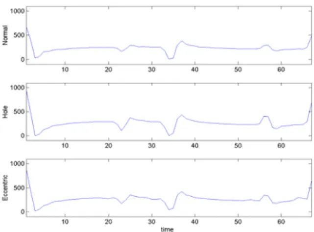
Time domain analysis of the stator current is shown in Fig. 5. They depict the time domain analysis results of the supposed normal condition bearing system, a hole drilled through the outer race of the shaft end bearing and shaft deflection system by external force of the four pole test motor, respectively. The experimental results show a uniform pattern with the peak to peak interval, and the magnitudes of pattern of bearings with a hole drilled through the outer raceway and shaft deflection by external force have the higher values than that of the normal bearing system
.
4.2. Fault detection technique 2(FFT: Fast Fourier
Transform)
Generally, induction motor fault detection via FFT-based stator current signature analysis could be improved by decreasing the current waveform distortions as is illustrated by Fig. 6. Moreover, it is well known that motor current is a non-stationary signal, the properties of which vary with the time varying normal operating conditions of the motor. As a result, it is difficult to differentiate fault conditions from the normal operating conditions of the motor using Fourier analysis. The maximum frequency of horizontal line in Fig. 6 is 1000Hz. This figures show that the current spectrum of less than 500Hz is dominant.
Fig. 5 Time domain analysis of stator current signature
Fig. 6 Stator current power spectra of health, hole
and shaft deflection motor
4.3. Fault detection technique 3 (Wavelet analysis)
Wavelets are a recently developed mathematical tool
for signal analysis. Informally, a wavelet is short-term
duration wave. Wavelets are used as a kernel function in
an integral transform, much in the same way that sines
and cosines are used in Fourier analysis. The main
advantage of Wavelets analysis over Fourier analysis is
that it does not require time function involved to be
periodic. This means that wavelet could be applied for
the transient analysis and faults detection because, in
this case, the stator current is generally not a periodic
function of time. The wavelet technique can be used for
a localized analysis in the time-frequency or time scale
domain.
Fig. 7 shows the result of stator current spectrum by continuous Wavelet transform. Under the not sever situation of the bearing faults, It is also difficult to differentiate fault conditions from the normal operating conditions of the motor using Wavelet analysis.
Fig. 8 is alternately represented by
scale factor of Fig 7 as following
|
2 1)
,
(
|
)
(
∑
==
N n fn
a
W
a
W
(8)
Where,
N
is the number of collected signal,
a
is a
scale factor and
W
f( n
a
,
)
is the result of continuous
wavelet transform.
Fig. 8 Energy distribution by scale factor
Under the not sever situation of the bearing faults,
It is also difficult to differentiate fault conditions from the normal operating conditions of the motor using Wavelet analysis, even if we see a little difference low scale factor(from 0 to 30).4.4 Fault detection technique 4 (Inner product of
wave patterns)
From Fig. 1, it shows a repeatable signal pattern for 3 case motors. This signal repetition consists of 63 data from peak to peak. An average signal pattern for corresponding points of 10’s by arbitrarily choosing is described at Fig. 9.
Fig. 9 Averaged signal pattern
The normalized inner production of two different patterns is given by normal N i i i n
a
b
IP
IP
(
)
/
1∑
=•
=
(9)Where,
IP
normalis the inner product of normal patterns anda
i,
b
i(
i
=
1
,...,
63
)
are the element of eachpatterns.
Table 1. Normalized Inner Product Normal Hole Eccentric
1 1.1133 1.1805 1.1998 2 1.1000 1.1997 1.1956 3 1.1112 1.1767 1.1868 4 1.1100 1.1801 1.1990 5 1.1138 1.1770 1.1918 6 1.1064 1.1699 1.1851 7 1.1231 1.1895 1.2036 8 1.1155 1.1973 1.1873 9 1.0967 1.1934 0.9443 10 1.1205 1.1954 1.1712
The result of Equation 9 shows in the table 1. The numerical values of the holed and eccentric bearing are more higher than the normal condition bearing except 9th eccentric case. Also it shows the eccentric case is a little higher than holed case. Proposed inner product of pattern is not required a mass calculation time like FFT, Wavelet and others. So, it is suitable to MPU or DSP in sense of less computation and required memory size. We can improve the reliability by comparing different patterns which are stored on MPU/DSP.
VI.
C
ONCLUSIONSWe have focused our research on so called motor current signature analysis. To carry out this research, therefore, this paper takes the initial step of investigating the efficacy of current monitoring for bearing fault detection by incipient bearing failure. Our group has developed the embedded distributed fault tolerant and fault diagnosis system for industrial motor. These mechanisms are based on two 32-bit DSPs and each TMS320F2407 DSP module is checking stator current, voltage, temperatures, vibration and speed of the motor. The DSPs share information from each sensor or DSP through DPRAM with hardware implemented semaphore. And it communicates the motor status through field bus (CAN, RS485). We set the experimental test bed to detect the rolling element bearing misalignment of 3 type induction motors with normal condition bearing system, shaft deflection system by external force and a hole drilled through the outer race of the shaft end bearing of the four pole test motor. The failure modes are reviewed and the characteristics of bearing frequency associated with the physical construction of the bearings are defined. The effects on the stator current spectrum are described and related frequencies are also determined. This is an important result in the formulation of a
fault detection scheme that monitors the stator currents. We utilized the FFT, Wavelet analysis and averaging signal pattern tool to analyze stator current components.
A
PPENDIXRated parameters of the machine under test
Power
1.5
kW
Frequency
60
Hz
Voltage(
∆
/Y)
220/380
V
Current (
∆
/Y)
3
A
Speed
1800
rpm
Pole pair(p)
2
A
CKNOWLEDGMENTThe authors would like to gratefully acknowledge the financial support of KESRI (Korea Electrical Engineering & Science Research Institute) and also ETPT of KEPRI under the project number A3050.
REFERENCES
[1] O.V. Thorsen et al.,” A survey of faults on induction motor in offshore oil industry, petrochemical industry, gas terminals, and oil refineries”, IEEE Trans. Industry application, Vol. 31, pp. 1186-1196, Sept./Oct., 1995. [2] M.E.H.Benbouzid, “Bibliography on induction faults
detection and diagnosis”, IEEE Trans. Energy Conversion, Vol. 14, No. 4, pp. 1065-1074, DEC., 1999. [3] M.E.H. Benbouzid et al., “What stator current
processing-based technique to use induction motor rotor faults diagnosis”, IEEE Trans. Energy Conversion, Vol. 18, No. 2, June 2003.
[4] IAS Motor Reliability Working Group, “ Report of large motor reliability survey of industrial and commercial installations: Part I, ” IEEE Trans. Industrial Application, Vol. 21, No. 4, pp. 853-864, July 1985.
[5] P.Eschman et al., “Ball and Roller bearings: Their Theory, Design, and Application”, K.G Heyden, 1958.
[6] R.A. Collacott, “Vibration Monitoring and Diagnosis”, John Wiley & Sons, pp. 109-111, 1979.
[7] R.R. Shoen et al., “Effect of time varying load on rotor fault detection in induction machines”, in Conf. Rec. 28th Annual IAS Meeting, Oct. 1993, pp324-330.
[8] R.R Shoen et al., “Motor bearing damage detection using stator current monitoring”, IEEE Trans., Ind. Application, Vol. 31, pp. 1274-1279, Nov./Dec. 1995.
[9] R. L. Schiltz, “Forcing frequency identification of rolling element bearing”, Sound and Vibration, pp. 16-19, May 1990.
[10] L. Cohen,” Time frequency Analysis”, Prentice-Hall, 1995.
[11] S.H Lee et al., “Introduction to the Wavelet Transform, Jinhan Book Inc., 2002.