Preliminary Design of the Liquid Lead Corrosion Test Loop
Chungho Cho, JaeEun Cha, Choonho Cho, Tae Yung Song, and Hee Reyoung KimKorea Atomic Energy Research Institute, 150 Deokjin-dong, Yuseoung-gu, Daejeon, 305-353, South Korea [email protected]
1. Introduction
Recently, Lead-Bismuth Eutectic (LBE) or Lead has newly attracted considerable attraction as a coolant to get the more inherent safety. Above all, LBE is preferred as the coolant and target material for an Accelerator-Driven System (ADS) due to its high production rate of neutrons, effective heat removal, and good radiation damage properties. But, the LBE or Lead as a coolant has a challenging problem that the LBE or Lead is more corrosive to the construction materials and fuel cladding material than the sodium because the solubility of Ni, Cr and Fe is high [1, 2]. After all, the LBE or Lead corrosion has been considered as an important design limit factor of ADS and Liquid Metal cooled Fast Reactors (LMFR).
The Korea Atomic Energy Research Institute (KAERI) has been developing an ADS called HYPER.[3] HYPER is designed to transmute Transuranics (TRU), Tc-99 and I-129 coming from Pressurized Water Reactors (PWRs) and uses an LBE as a coolant and target material. Also, an experimental apparatuses for the compatibility of fuel cladding and structural material with the LBE or Lead are being under the construction or design [4].
The main objective of the present paper is introduction of Lead corrosion test loop which will be built the upside of the LBE corrosion test loop by the end of October of 2005.
2. Design of the Lead Corrosion Loop
Figure 1 shows the schematic diagram of the Lead corrosion test loop to be designed in KAERI.
Figure 1. The schematic diagram of the Lead corrosion test loop
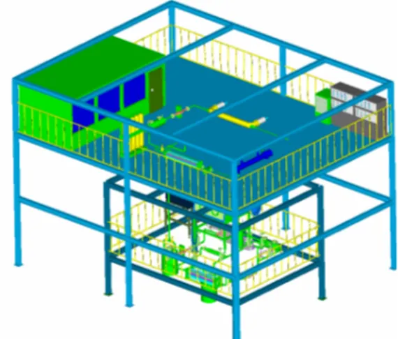
The Lead is used as the fluid for the corrosion test. The experimental apparatus consists of an Electro-Magnetic Pump (EMP), an Electro-Electro-Magnetic Flow meter (EMF), two test section, a heater, a cooler, an oxygen control tank (an expansion tank), and argon or argon with 5% hydrogen gas system. Figure 2 shows a bird’s-eye view of the LBE and Lead corrosion test loop.
Figure 2. Bird’s-eye view of the Lead corrosion test loop
Table 1 shows the major specifications of the Lead corrosion test loop. The velocity of the fluid is designed to be about 2m/s at the test section and the charging volume of Lead in the loop is up to 74 ℓ . In case of the normal operation, the flow rate of the Lead is 12 ℓ /min and the temperature of hot and cold region are 600℃ and 450℃, respectively.
The pressure drop of the main closed loop was estimated about 0.26MPa under the normal operation.
Table 1. The major specifications of the Lead corrosion test loop
Maximum test temperature 600℃
Maximum △T(hot – cold) 150℃
Heater and cooler power 45KW Number of Test section 2 ea Volume of Lead in the corrosion loop 74 liter Total pressure drop (normal operation) 0.26MPa Flow rate (normal operation) 12ℓ /min Velocity at the test section 2.0m/s There is EMP (60lpm-4bar, 40kVA) that sufficiently offers the driving force to be circulated the fluid for the corrosion test in the loop. The design and manufacture of the EMP are based on the EMP of the
Transactions of the Korean Nuclear Society Autumn Meeting Busan, Korea, October 27-28, 2005
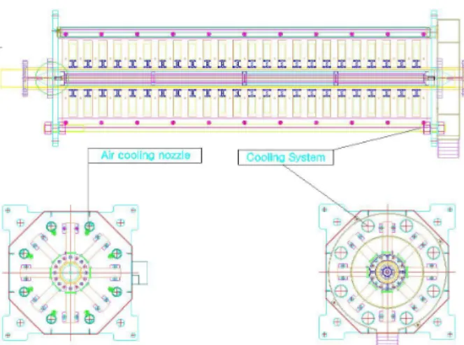
LBE corrosion test loop [5]. But, to rise the cooling effect at the pump-coil, the air shower hole is introduced. Figure 3 shows the EMP and the newly adopted air cooling system.
Figure 3. The EMP with the air cooling system
Most parts of the piping system except for the heater rods are made of STS316L stainless steel with 1.5cm inner diameter and the velocity of liquid Lead is 0.41 m/s. The total length of the piping system is about 20 m.
Figure 4. Schematics of the test section and test sample
There are two test sections. One is the hot region and another is the cold region. The maximum temperature of the former is 600℃ and the minimum temperature of the latter is 450℃. The maximum temperature difference in the Lead corrosion test loop is 150℃. Figure 4 shows the test section and test sample schematically.
The heater rods in the electronic heater are sheathed with 26Cr-2Mo ferritic stainless steel. The electric heater is flange immersion type and consists of the 30 heater rods with 15mm inner diameter and 1350mm heating length, which are installed in a 200mm casing diameter. The maximum heating power is 45kW.
Figure 5. Schematics of the electric heater
The air cooler consists of triple pipe with cooling fins which is installed in middle pipe of a 150mm diameter and inner pipe of a 32mm diameter. The maximum cooling power is 45kW.
Figure 6. Cross section view of the air cooler
3. Conclusion
KAERI recently finished detailed design of the Lead corrosion test loop. That consists of an electro-magnetic pump, an electro-electro-magnetic flow meter, two test section, a heater, a cooler, an oxygen control tank (an expansion tank), and argon or argon with 5% hydrogen gas system. KAERI will have built the Lead corrosion test loop by the end of October of 2005.
REFERENCES
1. G. Y. Lai, “High Temperature Corrosion of Engineering Alloys,” ASM Int. Materials Park, OH 44073, 1990.
2. Y. I. Orlov et al., “The Problems of Technology of the Heavy Liquid Metal Coolants (Lead-Bismuth, Lead),” Proc. of the Heavy Liquid Metal Coolants in Nuclear Technology, Obninsk, 1998.
3. W. S. Park et al., “Development of Nuclear Transmutation Technology,” KAERI Report, KAERI/RR-1702/96, 1996.
4. J. E. Cha et al., “Design of Corrosion Loop for Lead-Bismuth Eutectic,” Proc. Global 2003, New Orleans, 2003.
5. J. E. Cha et al., “Performance of Electromagnetic Pump for Lead-Bismuth Alloy,” Proc. KNS 2004.