M E T H O D O L O G Y
Open Access
Chair side measuring instrument for
quantification of the extent of a transverse
maxillary occlusal plane cant
Farhad B. Naini
1,2*, Ashraf Messiha
2and Daljit S. Gill
3Abstract
Background: Treatment planning the correction of a transverse maxillary occlusal plane cant often involves a
degree of qualitative
“eyeballing”, with the attendant possibility of error in the estimated judgement. A simple chair
side technique permits quantification of the extent of asymmetry and thereby quantitative measurements for the
correction of the occlusal plane cant.
Methods: A measuring instrument may be constructed by soldering the edge of a stainless steel dental ruler at 90°
to the flat surface of a similar ruler. With the patient either standing in natural head position, or alternatively seated
upright in the dental chair, and a dental photographic retractor in situ, the flat under-surface of the horizontal part
of this measuring instrument is placed on a unilateral segment of a bilateral structure, e.g. the higher maxillary
canine orthodontic bracket hook. The vertical ruler is held next to the contralateral canine tooth, and the vertical
distance measured directly from the canine bracket to the flat under-surface of the horizontal part of the measuring
instrument.
Results: This vertical distance quantifies the overall extent of movement required to level the maxillary occlusal plane.
Conclusions: This measuring instrument and simple chair side technique helps to quantify the overall extent of
surgical levelling required and may be a useful additional technique in our clinical diagnostic armamentarium.
Keywords: Transverse cant, Occlusal plane, Orthognathic surgery, Symmetry
Background
Relative unilateral vertical over- or underdevelopment of
the maxilla and maxillary dentoalveolus leads to a
trans-verse cant of the maxillary occlusal plane [
1
]. Correction
of such a cant requires a Le Fort I level osteotomy,
followed by unilateral bone removal and superior
reposi-tioning, contralateral inferior repositioning and bone
grafting, or a combination of the two, in order to level
the maxillary occlusal plane [
2
]. The degree of unilateral
superior versus contralateral inferior repositioning
de-pends on the aesthetic parameters of maxillary incisor
exposure in repose and overall maxillary dentogingival
exposure on smiling [
1
,
2
]. Accurate planning to correct
such an asymmetry is paramount [
3
–
6
]. The following
instrument and chair side technique to quantify the
ex-tent of asymmetry have not been previously described.
Methods
A measuring instrument may be constructed by soldering
the edge of a double-sided stainless steel dental ruler at
90° to the flat surface of a similar ruler (Fig.
1
). With the
patient in natural head position, near a vertical plumb line
(forming a true vertical line), and a dental photographic
retractor in situ (Fig.
2
), the flat under-surface of the
hori-zontal part of this measuring instrument is placed on the
higher maxillary canine orthodontic bracket hook and
held perpendicular to the true vertical (Fig.
3
). The vertical
ruler is held next to the contralateral canine tooth, and
the vertical distance measured directly from the canine
bracket to the flat under-surface of the horizontal part of
the measuring instrument. Alternatively, if the patient is
© The Author(s). 2019 Open Access This article is distributed under the terms of the Creative Commons Attribution 4.0 International License (http://creativecommons.org/licenses/by/4.0/), which permits unrestricted use, distribution, and reproduction in any medium, provided you give appropriate credit to the original author(s) and the source, provide a link to the Creative Commons license, and indicate if changes were made.
* Correspondence:[email protected]
1
Kingston and St George’s Hospitals and St George’s Medical School, London, UK
2Maxillofacial Unit, St George’s Hospital Medical School, Blackshaw Road, London SW17 0QT, UK
Full list of author information is available at the end of the article
Maxillofacial Plastic and
Reconstructive Surgery
Naini et al. Maxillofacial Plastic and Reconstructive Surgery (2019) 41:21 https://doi.org/10.1186/s40902-019-0204-6
seated upright in the dental chair, the horizontal part of
the instrument may be held parallel to the interpupillary
line, assuming no vertical orbital dystopia is evident.
It is worth emphasising that the instrument may be
held relative to a true vertical plumb line hanging from
the ceiling if a patient has a severe craniofacial
asym-metry and vertical orbital dystopia. However, this is
usu-ally not the case in orthognathic patients, and we
suggest that when the interpupillary line is essentially
parallel (i.e. the absence of vertical orbital dystopia), then
the horizontal part of the instrument may be help
paral-lel to the interpupillary line.
Fig. 1 The measuring instrument is constructed by soldering the edge of a double-sided stainless steel dental ruler at 90° to the flat surface of a similar ruler. A double-sided ruler permits its use on the patient’s right and left sides as required. A right-angle gauge may be used to ensure a 90° angle
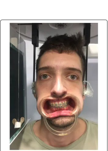
Fig. 2 Patient is shown in natural head position. The oral retractors are in situ, and a plumb line is evident hanging to the patient’s right side, which acts as a guide to the true vertical line. A transverse cant of the maxillary occlusal plane, down on the patient’s right side, is evident. The patient may be positioned in a cephalostat as demonstrated here, though this is not mandatory, and for most patients sitting in the dental chair will suffice
Fig. 3 The flat under-surface of the horizontal part of the measuring instrument is placed on the higher maxillary canine orthodontic bracket hook (though it may be placed on a unilateral segment of any bilateral structure), and held perpendicular to the true vertical. For patients with a relatively symmetrical upper face, and no vertical orbital dystopia, the horizontal part of the measuring instrument may be held approximately parallel to the interpupillary plane (a dental mirror handle may be held in line with the interpupillary plane, to aid visualisation at the chair side). The vertical ruler is held next to the contralateral canine tooth, and the vertical distance measured directly from the canine bracket to the flat under-surface of the horizontal part of the measuring instrument. This vertical distance quantifies the overall extent of movement required to level the maxillary occlusal plane
Results
The vertical distance thus measured quantifies the
over-all extent of movement required to level a transversely
canted maxillary occlusal plane.
Discussion
One of the key principles in planning the correction of
significant dentofacial asymmetries is levelling of the
max-illary occlusal plane [
1
]. This decision is made primarily
based on the aesthetic parameter of the maxillary incisor
and canine exposure in relation to the upper lip in repose,
and the degree and symmetry of the exposure of the
max-illary dentition and gingivae in animation [
1
,
2
]. If incisor
and canine exposure is reduced, unilateral setdown of the
maxilla may be required, albeit bearing in mind lower face
height proportion and implications for surgical stability.
Conversely, if dentogingival exposure is increased
unilat-erally, then ipsilateral maxillary impaction is the treatment
of choice. The degree of impaction versus setdown
re-quired to accurately level the maxillary occlusal plane
while maintaining or improving dentogingival aesthetics
requires accurate planning. In addition to the important
clinical and cephalometric techniques required for
preci-sion, the simple chair side technique potentially improves
visualisation and permits an additional verification to aid
both diagnosis and treatment planning for such patients.
Conclusions
This measuring instrument and simple chair side
tech-nique helps to quantify the overall extent of surgical
lev-elling required and may be a useful additional technique
in our clinical diagnostic armamentarium.
Acknowledgements Nil.
Funding None.
Availability of data and materials Not applicable.
Authors’ contributions
FBN conceived the idea, which was deliberated with AM and DSG and subsequently clinically verified by all authors. All authors helped to complete the manuscript and read and approved the final manuscript.
Ethics approval and consent to participate Ethical approval was not required.
Consent for publication
The subject in Figs.2and3provided written consent for his images to be published.
Competing interests
The authors declare that they have no competing interests.
Publisher
’s Note
Springer Nature remains neutral with regard to jurisdictional claims in published maps and institutional affiliations.
Author details
1Kingston and St George’s Hospitals and St George’s Medical School, London, UK.2Maxillofacial Unit, St George’s Hospital Medical School, Blackshaw Road, London SW17 0QT, UK.3Department of Orthodontics, Great Ormond Street Hospital & Eastman Dental Hospital, London, UK.
Received: 27 March 2019 Accepted: 15 April 2019
References
1. Naini FB (2011) Facial symmetry and asymmetry. In: Naini FB. Facial aesthetics: concepts and clinical diagnosis. Wiley-Blackwell, Oxford 2. Naini FB, Manisali M, Gill DS (2017) Asymmetries of the maxilla and
mandible. In: Naini FB, Gill DS (eds) Orthognathic surgery: principles, planning and practice. Wiley-Blackwell, Oxford
3. Quevedo L, Ruiz JV, Quevedo C (2011) Using a clinical protocol for orthognathic surgery and assessing a 3-dimensional virtual approach: current therapy. J Oral Maxillofac Surg 69:623–637
4. Xia JJ, Gateno J, Teichgraeber JF (2009) New clinical protocol to evaluate craniomaxillofacial deformity and plan surgical correction. J Oral Maxillofac Surg 67:2093–2106
5. Barbenel JC, Paul PE, Khambay BS, Walker FS, Moos KF, Ayoub AF (2010) Errors in orthognathic surgery planning: the effect of inaccurate study model orientation. Int J Oral Maxillofac Surg 39:1103–1108
6. Zhao L, Patel PK, Cohen M (2012) Application of virtual surgical planning with computer assisted design and manufacturing technology to cranio-maxillo-facial surgery. Arch Plastic Surg 39:309–316