한국추진공학회 2017년도 춘계학술대회 논문집 pp.704~708 2017 KSPE Spring Conference
Nomenclature
: diameter of swirl chamber oxidizer : diameter of orifice oxidizer
: diameter of tangential inlet oxidizer
: energy
: energy of phase
: gravity vector k : thermal conductivity
: effective thermal conductivity
n : number of phase
: number of tangential inlets oxidizer
p : pressure t : time T : temperature : velocity vector
: velocity vector phase
: symmetric velocity vector : volume fraction
: volume fraction of phase
: friction coefficient : density
: density of phase
1. Introduction
Computational Evaluation of Spray Characteristics in Swirl
Coaxial Injector with Varying Recess Length
Girishankar Kishore* ․ Seong Hun Bae*․ Jeong Soo Kim*†
ABSTRACT
A spray characteristics is carried out in a numerical simulation of swirl coaxial injector. The water and nitrogen are the oxidizer and fuel is used in cold flow condition . The simulation is carried out in 3d model with varying recess length. Reynolds stress turbulence and volume of fluid model were chosen to perform the simulation. The spray characteristics have been investigated as well as the influence of the inlet swirl strength of the internal flow. Effect of recess length is studied for the axial and radial velocity decreased with a reduced length of inner injector due to the decline vortex intensity.
Key Words: Swirl Injector , Volume of Fluid (VOF), Recess Length, Swirl Number
* 부경대학교 기계공학과
The swirl coaxial injector is used in the liquid bipropellant rocket engine especially in one of the best engines in the world: the RD-170 engine. There are many advantages for swirl injector some of them are lower drop pressure, lower chamber length, homogeneous atomization and combustion stability. The swirl injector compose of both oxidizer and fuel.
To produce a good atomization, a high relative velocity between the liquid to be atomized and the surrounding air or gas is required. In swirl coaxial injector, a separate swirl chamber with tangential slots or swirl piece (with helical or tangential passage) is provided to upstream of the circular exit orifice Bae et al. [1]. Due to the swirling motion provided to the liquid, an air core is formed, which is surrounded by the liquid sheet that emerges the orifice as a thinning sheet, which is unstable, breaking up to ligaments and droplets. Swirl number is used to characterize such atomizers, which is the ratio of circumferential velocity of liquid to its axial velocity G.Ranuzzi et al. [2]. As swirl number increases spray cone also increase.
For injector design, five recess length has been regarded as a key parameter for the design. It is defined as the axial distance between end of shielding and injector nozzle exit A.A.Baharanch et al. [3]. They showed that absence of the recess region delays mixing, extending the mixing area further downstream, and diminish mixing efficiency Xingjian Wang et al. [4].
In this paper, the numerical study is applied to investigate the spray characteristics in the swirl injector. The objective of this paper is to get the optimized the mixing of both water and nitrogen in cold flow condition. The Fig. 1 shows the schematic and location of the various parts of the injector. The inner swirl
injector with four tangential inlets with respective to 90.
2. Numerical Methodology 2.1 Numerical Method
The flow variables in the computational domain have been calculated numerically using the governing equations such as continuity, momentum and energy equations with respective to VOF (Volume Of Fluid) in an implicit scheme method.
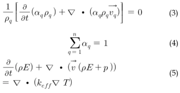
The mass conservation eq. 1, momentum conservation eq. 2 and energy equation eq. 5.
∇ ∙ (1) where is the fluid density, t is time and is flow velocity of the vector field
∇ ∙
∇ ∇ ∙ ∇ ∇ (2) The momentum equation, shown above, is dependent on the volume fractions of all phases through the properties and . The tracking of the interfaces between the phases is accomplished by the eq. 3 is explained well.
∇ ∙
(3)
(4)
∇ ∙
∇ ∙ ∇
(5) The primary phase volume fraction is eq. 4. In the eq. 5 VOF model treats energy, E and temperature, T, as mass averaged variables:
(6)In the eq. 6 where
for each phase isbased on the specific heat of that phase and the shared temperature. The properties and (effective thermal conductivity) are shared by the phase.
2.2 Turbulence model
In this paper the turbulence model is based on the swirl number. Its a dimensionless number it helps to determine the swirl strength. The strength of the swirl is gauged by the swirl number S, defined as the ratio of the axial flux of angular momentum to the axial flux of the axial momentum eq. 7.
As of the geometry configuration the swirl number is greater than 0.5, so it is a highly swirling flow recommend to use RSM (Reynolds Stress Model) with pressure based solver and density as ideal gas. In solution method we used the first order upwind
discretization for all transported scalar. For the five cases 170,000 to 176,000 nodes and 750,000 to 763,000 elements is generated. The Fig. 2 represents the computational domain of injector.
3. Geometry Configuration and Boundary Conditions The Table 1 represents the recess length of the injector along the axial direction. where
represents the diameter of the inner injector orifice. The Table 2 represents the boundary
(7)
Fig. 2 Computational domain.
Case 1 2 3 4 5
R/ 0 1 1.5 2 2.5
Table 1. Parametric variation of the recess length.
Oxidizer (water) Fuel (nitrogen) Velocity Inlet,(m/s) 13.2 5 Operating Pressure,(Pa) 101,325 101,325 Temperature (K) 300 300
Wall No slip, Adiabatic condition Table 2. Boundary conditions.
condition of the injector where the velocity inlet for water is the total velocity of the 4 tangential inlets and the fuel inlet which goes in a jet flow in the axial direction, And temperature and pressure are maintained at atmospheric condition.
4. Result and Discussion
The calculation is performed for the cold flow dynamics. where Fig. 3 and 4 shows a instantaneous distribution of the axial and radial velocity in the radial direction of the outlet. The strong swirling motion and its ensuring the centrifugal force produce large
pressure gradient in the axial and radial direction. From the both figure we can conclude that case 3 shows a good result its due to the potential core of the water and nitrogen interaction. There are some positive and negative pressure gradient its due to the recirculation of the water flowing through the outlet. From the 5 cases the case 3 shows a valuable result its due to the recess length of the inner and outer injector where as the other case getting reduced due to the recess length and mixing of the water and nitrogen.
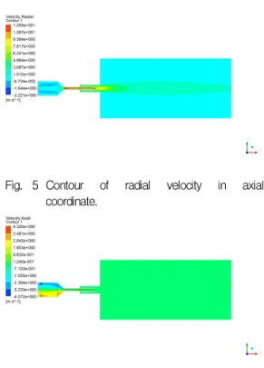
The radial velocity and axial velocity graph Fig. 5 and Fig.6 shows how the flow of the mixture of water and nitrogen flows through the outlet. In the graph also the case 3 shows a good result among the other recess length. From the above result we can conclude that recess length plays a vital role in the mixing of both oxidizer and fuel that is water and Fig. 5 Contour of radial velocity in axial
coordinate.
Fig. 6 Contour of axial velocity in axial coordinate. Fig, 3 Radial velocity vs distance from the swirl
exit.
nitrogen. The water comes in a recirculation zone and the nitrogen interacts with it and makes it into a droplet and ligaments. The contour shows the flow dynamics in the radial and axial direction of the injector.
5. Conclusion
Flow dynamics of the water and nitrogen of the swirl injector is calculated under cold flow conditions. The recess length plays a vital role in the mixing of the oxidizer and nitrogen inside the injector. From the above result the case 3 shows a good mixing of water and nitrogen. Based on the analysis the internal flow of the swirl injector gets recirculation in the outlet and the nitrogen which comes in a jet makes it to reduce the flow in a narrow. The spray characteristics have been calculated based on recess length with the axial and radial velocity.
6. Acknowledgement
This work was partly supported by NSL
(National Space Lab) program
(NRF-2016M1A3A3A02018009) and Basic
Science Research program
(NRF-2016R1D1A3B01012622) through the National Research Foundation of Korea (NRF) funded by Ministry of Science, ICT and Future Planning
References
1. Bae, S.H., Jung, H. and Kim, J.S., “ A Preliminary Configuration Design of Methane/Oxygen Bipropellant Small-rocket-engine through Theoretical Performance Analysis,” Journal of the Korean Society of Propulsion Engineers, Vol. 19, NO. 3, pp. 47-53, 2015.
2. Ranuzzi, G., Cutrone, L., Cardillo, D. and Invigorito, M., “Numerical Investigation of Rocket Engine Combustion Flow fields," 54th AIAA Aerospace Sciences Meeting, San Diego, California, USA., January 2016, 3. Baharanchi, A.A., Gokaltun, S. and
Eshraghi, S., “A Numerical Approach for the Simulation of Internal Nozzle Flow in a Pressure Swirl Atomizer Using Different Turbulent Models and Towards an Effective Inlet Weber Number," Proceedings of the ASME 2013 International Mechanical engineering congress and Exposition. , San Diego, California, USA., November 2013 4 Xingjian, W. and Vigor, Y., “Supercritical
Mixing and Combustion of Liquid – Oxygen/ Kerosene Bi-Swirl Injectors,” Journal of Propulsion and Power. Vol. 33, No. 2 , pp. 316-322, July 28 2016
5. Arun, S. and Rakesh, P., “Computational evaluation of spray characteristics in pressure swirl atomizers," International journal of scientific and engineering research, Vol 5, issue 7, pp. 804-808, 2014.
6. ANSYS, INC., ANSYS FLUENT 14.5 Theory Guide, 2012.