H E A L T H A N D M E D I C I N E
Wirelessly controlled, bioresorbable drug delivery
device with active valves that exploit electrochemically
triggered crevice corrosion
Jahyun Koo1*, Sung Bong Kim2,3,4*, Yeon Sik Choi2,3*, Zhaoqian Xie5*, Amay J. Bandodkar2,3,
Jawad Khalifeh6, Ying Yan6, Hojun Kim7,8, Maryam Kherad Pezhouh9, Karen Doty10,
Geumbee Lee2,3, Yu-Yu Chen4, Seung Min Lee11, Dominic D'Andrea12, Kimin Jung13,
KunHyuck Lee2,3, Kan Li2,14, Seongbin Jo4, Heling Wang2,14, Jae-Hwan Kim2,3,4,
Jeonghyun Kim15, Sung-Geun Choi11, Woo Jin Jang4, Yong Suk Oh3,16, Inkyu Park16,
Sung Soo Kwak2,3, Ji-Hyeon Park17, Doosun Hong13, Xue Feng18, Chi-Hwan Lee19,
Anthony Banks2,3, Cecilia Leal7, Hyuck Mo Lee13, Yonggang Huang2,3,14, Colin K. Franz12,20,
Wilson Z. Ray6,21, Matthew MacEwan6,21†, Seung-Kyun Kang11,22†, John A. Rogers2,3,9,14,23,24†
Implantable drug release platforms that offer wirelessly programmable control over pharmacokinetics have potential in advanced treatment protocols for hormone imbalances, malignant cancers, diabetic conditions, and others. We present a system with this type of functionality in which the constituent materials undergo com-plete bioresorption to eliminate device load from the patient after completing the final stage of the release pro-cess. Here, bioresorbable polyanhydride reservoirs store drugs in defined reservoirs without leakage until wirelessly triggered valve structures open to allow release. These valves operate through an electrochemical mechanism of geometrically accelerated corrosion induced by passage of electrical current from a wireless, bioresorbable power-harvesting unit. Evaluations in cell cultures demonstrate the efficacy of this technology for the treatment of cancerous tissues by release of the drug doxorubicin. Complete in vivo studies of platforms with multiple, inde-pendently controlled release events in live-animal models illustrate capabilities for control of blood glucose levels by timed delivery of insulin.
INTRODUCTION
Implantable devices for drug delivery offer powerful capabilities in localized and controlled pharmacological treatments, where structural designs and/or material properties support the necessary functionality. Most of these platforms rely on passive drug diffu-sion from porous scaffolds or on release from soft polymer matri-ces that biodegrade over time (1–4). These devimatri-ces operate on the basis of diffusion-controlled leakage of drug molecules, with rates that depend on the state of the system as it interacts with the sur-rounding biology. Although technologies with electronically pro-grammable valves built into reservoirs and fluidic channels enable much greater versatility in the controlled drug release kinetics (5–7),
secondary surgical procedures to extract the implanted hardware after completion of the delivery function are required. To overcome these key disadvantages, drug delivery platforms should ideally in-corporate (i) active systems with wireless control, (ii) mechanically stable reservoir structures with complete sealing for zero leakage of drugs in the off state and compatibility with any drug chemistry, and (iii) fully bioresorbable construction to eliminate the need for secondary surgical removal processes after treatment.
Recent reports describe active classes of bioresorbable elec-tronic systems that store drugs in porous polymer molecular matri-ces or chemically conjugated polymer structures, where wirelessly delivered thermal stimuli trigger the release processes (8–10). Tao et al. (8) 1School of Biomedical Engineering, Korea University, Seoul 02841, Republic of Korea. 2Department of Materials Science Engineering, Northwestern University, Evanston,
IL 60208, USA. 3Center for Bio-Integrated Electronics, Northwestern University, Evanston, IL 60208, USA. 4Materials Research Laboratory, University of Illinois at Urbana-
Champaign, Urbana, IL 61801, USA. 5State Key Laboratory of Structural Analysis for Industrial Equipment, Department of Engineering Mechanics, International Research
Center for Computational Mechanics, Dalian University of Technology, Dalian 116024, China. 6Department of Neurological Surgery, Washington University School of
Medicine, St. Louis, MO 63110, USA. 7Department of Materials Science and Engineering, University of Illinois at Urbana-Champaign, Urbana, IL 61801, USA. 8Center for
Biomaterials, Biomedical Research Institute, Korea Institute of Science and Technology (KIST), Seoul 02792, Republic of Korea. 9Feinberg School of Medicine, Northwestern
University, Evanston, IL 60208, USA. 10Department of Comparative Biosciences Histology Service Laboratory, University of Illinois at Urbana-Champaign, Urbana, IL 61801,
USA. 11Department of Materials Science and Engineering, Seoul National University, Seoul 08826, Republic of Korea. 12Regenerative Neurorehabilitation Laboratory,
Shirley Ryan Ability Lab, Chicago, IL 60611, USA. 13Department of Materials Science and Engineering, Korea Advanced Institute of Science Technology, Daejeon 34141, Republic
of Korea. 14Department of Civil and Environmental Engineering, Northwestern University, Evanston, IL 60208, USA. 15Department of Electronics Convergence
Engi-neering, Kwangwoon University, Nowon-gu, Seoul 01897, Republic of Korea. 16Department of Mechanical Engineering, Korea Advanced Institute of Science and
Technology, 291 Daehak-ro, Yuseong-gu, Daejeon 34141, Republic of Korea. 17Korea Institute of Ceramic Engineering and Technology, 15-5, Chungmugong-dong,
Jinju-si, Gyeongsangnam-do 52851, Republic of Korea. 18AML, Department of Engineering Mechanics, Center for Mechanics and Materials, Tsinghua University, Beijing
100084, China. 19Weldon School of Biomedical Engineering and School of Mechanical Engineering, Purdue University, West Lafayette, IN 47907, USA. 20Departments of
Physical Medicine and Rehabilitation, and Neurology, Northwestern University Feinberg School of Medicine, Chicago, IL 60611, USA. 21Department of Biomedical
Engi-neering, Washington University, St. Louis, MO 63110, USA. 22Research Institute of Advanced Materials, Seoul National University, Seoul 08826, Republic of Korea. 23Querrey Simpson Institute for Bioelectronics, Northwestern University, Evanston, IL 60208, USA. 24McCormick School of Engineering, Northwestern University, Evanston,
IL 60208, USA.
*These authors contributed equally to this work.
†Corresponding author. Email: jrogers@northwestern.edu (J.A.R.); kskg7227@snu.ac.kr (S.-K.K.); macewanm@wustl.edu (M.M.)
Copyright © 2020 The Authors, some rights reserved; exclusive licensee American Association for the Advancement of Science. No claim to original U.S. Government Works. Distributed under a Creative Commons Attribution NonCommercial License 4.0 (CC BY-NC). on April 27, 2021 http://advances.sciencemag.org/ Downloaded from
describe thermally accelerated drug release devices that use a silk-based structure, but with rapid rates of degradation and disinte-gration, often within timescales of minutes or hours. Lee et al. (9) report electronically programmable devices based on temperature- sensitive lipid-based structures. A disadvantage is that the lipid can collapse due to its weak molecular bonding, leading to unwanted leakage of drugs. Another approach (10) uses a wireless, thermal actu-ation scheme to release physically trapped and covalently con-jugated drug molecules from an oxidized starch–based structure. In particular, hydrophilic drug molecules remain within the materials structure, and heating (~42°C) accelerates diffusive release. Although these hyperthermic platforms (8–12) offer advantages over many other options, limitations follow from their sensitivity to uncon-trolled variations in temperature over a narrow operating range, mechanical perturbations, and/or swelling of the polymer matrices during or after implantation. Moreover, these platforms are not drug release vehicles in the engineering sense of reservoirs, valves, channels, and other fluid handling systems. As a result, the pay-loads and release kinetics are constrained by the degradable matrix and the nature of the molecular interactions that are responsible for binding.
Here, we introduce an approach that allows deterministic con-trol over the delivery process in the form of a completely bioresorb-able electronic system that combines biocompatible wireless power-harvesting function with electrochemically degradable valves and a system of reservoirs constructed from a bioresorbable poly-mer. The result provides for programmable control over drug re-lease in a platform that disappears completely and naturally in the body without residue. Specifically, wirelessly delivered electrical current initiated by proximity to a transmission coil leads to electrochemically accelerated dissolution of a metal gate structure that seals drug- containing reservoirs constructed in a bioresorbable polyanhydride. Unlike hyperthermic actuation (8–12), this crevice corrosion phe-nomenon for opening of the gate enables fast and energy-efficient drug release. Exploiting this scheme using metal gates with various shapes and sizes allows the delivery of effective doses to target tissues with desired kinetics. As a result, this technology enables in situ, on-demand release of single or multiple classes of drugs from a collection of independently controlled reservoirs, with precise control of the release timing and near-zero parasitic leakage over extended periods of time. Systematic in vivo and in vitro studies demonstrate the underlying principles and all of the relevant fea-tures of operation.
RESULTS AND DISCUSSIONS
Structure and operation of bioresorbable, wireless drug delivery device
Figure 1A highlights the design aspects and key materials for a simple system of this type, consisting of a polymer reservoir, a wireless power harvester, and a metal gate valve. Polybutanedithiol 1,3,5-triallyl- 1,3,5-triazine-2,4,6(1H,3H,5H)-trione penteonic anhydride (PBTPA), a bioresorbable polyanhydride (13), serves as a substrate and a containment vessel for an aqueous drug of interest. Synthesis of the PBTPA relies on thiol-ene click reactions of three compounds ini-tiated by exposure to ultraviolet (UV) light: 4-pentenoic anhydride (4PA), 1,3,5-triallyl-1,3,5-triazine-2,4,6(1H,3H,5H)-trione (TTT), and 1,4-butanedithiol. The UV curing process facilitates the use of molding and/or machining techniques, to yield platforms of this
type with a range of sizes and shapes, as indicated in fig. S1. The simple example shown here involves a single reservoir, with a pair of magnesium (Mg) electrodes assembled with the PBTPA housing. The wireless power harvester relies on magnetic inductive coupling to an external transmission coil to produce an electrical bias be-tween the Mg electrodes, where one serves as an anode (referred to as the gate, which functions as the valve to an underlying reservoir) and the other as the cathode. This harvesting unit consists of a ra-dio frequency (RF) coil of Mg, an RF ra-diode constructed using a silicon nanomembrane (Si NM), and a parallel-plate capacitor in a
multilayer stack of Mg/SiO2/Mg, as shown in Fig. 1A(i). The
reso-nance frequency is ~5 MHz, as shown in Fig. 1B, with scattering parameters, quality factor, and inductance values consistent with com-putational modeling (note S1). Magnetic coupling at this frequency involves negligible parasitic absorption by biological tissues (14, 15). A relatively high Q ~ 15 (Fig. 1C) allows for long operating dis-tances (~5 cm). A transmission coil (80-mm diameter, 3 turns, and winding with 1.6-mm diameter copper wire) added to the simulation model yields a relationship between the power transfer efficiency and operating distance, as shown in Fig. 1D (detailed information is in note S1).
The optimized power harvester generates an overpotential (bias), which leads to accelerated electrochemical etching with geometrical effects induced by the PBTPA housing. First, a bias develops be-tween the anode gate and the cathode upon activation of an RF transmission coil placed in proximity to the device (14). This bias results in irreversible Faradaic reactions enabled by surround-ing biofluids (15), accordsurround-ing to the followsurround-ing anodic reaction:
(Mg → Mg2+ + 2e−) (16). This reaction opens the gate and causes
the release of drug from the underlying reservoir. Figure 1E demon-strates wirelessly controlled release of water (4 ml, dyed blue) from a reservoir of a device immersed in a bath of phosphate-buffered saline (PBS; Sigma-Aldrich, USA) due to opening of the gate by electrochemical etching induced by passage of RF power (~12 mW into the receiver coil; 8 W into the transmission coil) through a transmission coil located at a distance of 2 cm outside of the bath. This process induces no notable heating (fig. S2). In this manner, the system supports the wirelessly controlled release of drugs, on- demand and with access to various amounts of drug solution (micro- to milliliter), as key advantages compared to conventional systemic delivery.
Dissolution studies of whole drug delivery system
A key defining characteristic of the system is that all of its constituent parts undergo complete dissolution into biocompatible end-products (17). Figure 1F illustrates the processes associated with accelerated dissolution of the entire system in a bath of PBS (pH 7.4) at 85°C for more than 4 weeks, including the PBTPA reservoir (100 m), the Mg (50 m, ~100 g) RF coil encapsulated by PBTPA (20 m),
Si NM (320 nm) RF diode, and Mg/SiO2/Mg (30 m/100 nm/30 m)
capacitor (fig. S3). The rate of dissolution of PBTPA can be adjusted through control of the molar ratios of 4PA, TTT, and 1,4-butanedithiol, which for cases explored here are 1:4:7 (referred to as PBTPA 1:4:7) and 1:1:2.5 (referred to as PBTPA 1:1:2.5) (13). The results of Fig. 1F use the latter formulation. Since the 4PA contains hydrophilic and degradable bonds and 1,4-butanedithiol provides hydrophobic chains, a high ratio of 1,4-butanedithiol in PBTPA (1:4:7) extends the time for dissolution. The corresponding time at body temperature can be estimated from results obtained at elevated temperatures and
on April 27, 2021
http://advances.sciencemag.org/
associated Arrhenius scaling relationships to approximate the tem-perature dependence (18)
k PBTPA = k 0 ‧ exp(− E A / RT)
where k0 is the preexponential factor, EA is the activation energy,
R is the universal gas constant (=8.314 J∙K−1 mol−1), and T is the
absolute temperature. Measured rates of dissolution of the PBTPA (1:1:2.5) at different temperatures (0.5, 6.7, and 16.3 mg/day at 23°,
60°, and 85°C, respectively), yield values of k0 and EA as 3.29 × 10⁸
and 51,500 J∙mol−1, respectively (fig. S4). As a result, the PBTPA
reservoir (1:1:2.5, 450 mg, 100 m thick) has a projected lifetime of ~660 days at 37°C in PBS (pH 7.4). The other individual components of the system dissolve more quickly than the reservoir, ~50 days for the Mg (50 m) coils (19), ~100 days for the Si NM (320 nm) diode
(20), ~60 days for the Mg/SiO2/Mg (30 m/100 nm/30 m) capacitor
(21), and ~30 days for the Mg (30 m) electrodes. The time for dis-solution of the system can be reduced by decreasing the thickness of Fig. 1. Wirelessly programmable, bioresorbable drug delivery system. (A) Illustration and images of an implantable and wirelessly controlled bioresorbable drug
delivery system with an electrical triggering unit that includes a radio frequency (RF) power harvester with a Mg coil, a silicon nanomembrane (Si NM) diode, and a Mg/SiO2/Mg capacitor, [A(i)]. (B) RF behavior (scattering parameter, S11) of the harvester (black, experiment; blue, simulation). The resonance frequency is ~5 MHz, selected
to allow magnetic coupling with little parasitic absorption by biological tissues. (C) Simulated inductance (black) and Q factor (red) of a single coil with a diameter of 16 mm. (D) Transmitting power as a function of the distance between the transmitting coil and the device (black, experiments; red, simulation). Experimental data are means ± SD; n = 3. (E) Images of wirelessly controlled release of a blue dye in water during immersion in phosphate-buffered solution (PBS; pH 7.4). (F) Accelerated dis-solution of an entire system due to immersion in PBS (pH 7.4) at an elevated temperature, 85°C. Photo credit: Jahyun Koo, Korea University.
on April 27, 2021
http://advances.sciencemag.org/
the PBTPA or by adjusting the molar ratios of the reactant chemi-cals, to values in the range of a few hundred days.
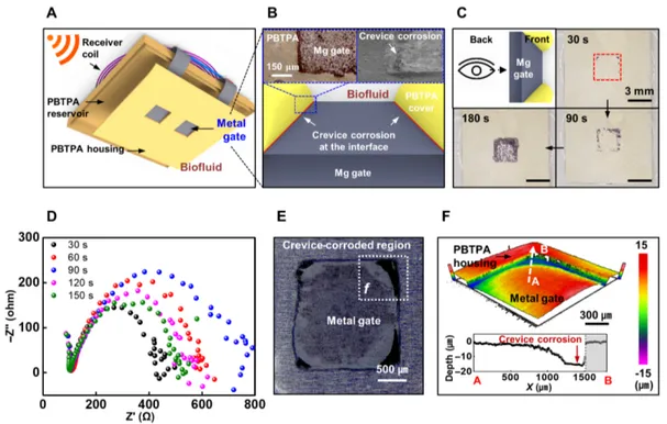
Opening mechanism by electrochemically triggered crevice corrosion
A critically important aspect of the release mechanism is that the confined geometry at the interface between the gate and PBTPA housing leads to accelerated rates of electrochemical etching, some-times referred to as crevice corrosion (16, 22, 23), as shown in Fig. 2A. Figure 2B presents an illustration and a set of images of the system and the location of the gate defined by the housing. The insets of Fig. 2B show optical microscope (OM; left) and scanning electron microscope (SEM; right) images of the results of electro-chemical etching with a bias of 1 V for 180 s. Images of the backside of the gate shown in Fig. 2C and fig. S5 illustrate that the highest etching rates occur at the vertices, followed by the edges. Electro-chemical impedance spectroscopy (EIS) measurements performed at regular time points during the etching process yield insights into the gate morphology and the gate-electrolyte interface. Figure S6A shows a schematic illustration of the interfaces between the gate and biofluid and of a Randles’ equivalent circuit (24). Here, the solution
resistance (Rs), the charge transfer resistance (Rct), and the constant
phase element (CCFE) define the nature of the electrochemical
pro-cesses (fig. S6B). A factor “n” in equation (jC = (j)nC
CPE) varies
between a value of 1 and 0, with the higher extremity representing a pure capacitor while the lower characterizing a resistor. When n is
between 0 and 1, its value provides information about diffusion phenomena, surface morphology, and other dissipative processes (25). After etching for 30 s, the value of n tends to decrease, likely due to increasing roughness and/or porosity on the surface of the electrode, as expected (26, 27) and as observed in SEM images (fig. S7). Although the initial electrode surface likely supports a thin
oxide layer, electrochemical etching forms Mg(OH)2 according to
Mg + 2H2O → Mg(OH)2 + H2. The combined effect of the oxide
and hydroxide, which are both simultaneously forming and dissolv-ing into the surrounddissolv-ing biofluids throughout the process (19, 28), leads to capacitive behavior between the electrolyte and electrode. As the etching proceeds, the thickness of the corrosion layer (d) increases, thereby decreasing the capacitance (C) according to
C = 0S · d−1 (where 0, , and S are the vacuum permittivity, dielectric
constant, and surface area of the electrode, respectively) (fig. S6) (29). After termination of electrochemical etching under applied bias,
the residual Mg(OH)2 and oxides eventually disappear completely
via dissolution at rates of several nanometers per day, depending on the details of the chemistry of the surrounding solution (19).
Quantitative characterization of the crevice corrosion phenomena is most easily conducted with molybdenum (Mo) gates (10 m thick), due to the comparatively smooth morphology of the thin
oxide film (MoO3) and the reduced rates of dissolution compared
to Mg. The central region, away from the perimeter, exhibits the slowest rates. A magnified OM image of the gate and an optical profilometry image at a vertex (Nexview, Zygo Corporation, USA)
Fig. 2. Geometrically accelerated corrosion as the mechanism for opening a gate. (A) Design of an implantable and wirelessly controlled, bioresorbable drug delivery
system. (B) Illustration and image of a Mg gate defined by an opening through a cover of PBTPA. The locations where the edges of this opening meet the underlying Mg create regions of crevice corrosion. The insets show optical microscope (OM; left) and scanning electron microscope (SEM; right) images of the electrochemically accelerated corrosion that occurs along these edge locations. (C) Back side view images of an electrochemically etched Mg gate (3 mm by 3 mm) at an applied potential of 1 V (~5 mA) for 0, 30, 90, and 180 s, respectively. (D) Nyquist plot: Z′, real part of impedance; Z′′, imaginary part of impedance. (E) OM image of the electrochemically accelerated corrosion of a Mo gate (3 mm by 3 mm, 10 m thick) at an applied voltage of 5 V (~6 mA) for 60 s. (F) Three-dimensional (3D) topography image and surface profile measurement of the corroded Mo gate near the edge of the PBTPA (1:1:2.5) opening, obtained using a 3D optical profiler (Nexview, Zygo Corporation, USA). Photo credit: Ji-Hyeon Park, Northwestern University.
on April 27, 2021
http://advances.sciencemag.org/
in Fig. 2 (E and F) confirm the differential rates of corrosion ki-netics across different regions. The relative depth of the corrosion along the white arrow with the broken line (between A and B) in Fig. 2F indicates that the corrosion rates at the edges and vertex regions are ~10 times higher than that at the central region, i.e.,
~5.6 × 10⁻⁸ and ~4.1 × 10⁻⁹ mg‧mm2‧s−1, respectively. These rates
follow from estimates of the areas for uniform (~280 mm2) and
crevice (~26 mm2) corrosion determined from the OM image
(1 V for 200 s) and from the etched Mo volume extracted from the three-dimensional topology data (fig. S8A). These observations are consistent with crevice corrosion processes that arise at dissimilar junctions (16, 22, 23) due to reduced rates of mass transfer at the edges and associated enhancements in anodic effects. Figure S8B presents sequential images of the structure at 10, 20, and 30 s of electrochemical etching with a bias of 5 V. The images illustrate that the crevice corrosion at the perimeter of the anode dictates the opening of the gate and associated release. As a result, only a rela-tively small amount of the gate (i.e., along the perimeter) must be etched away to produce an opening event, thereby allowing for the rapid release of drugs upon a trigger event.
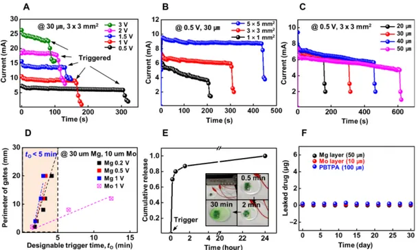
Trigger and release behaviors of bioresorbable drug delivery device
Figure 3 (A to D) summarizes the effect of applied voltage, gate area,
and thickness on the time required to open the gate (t0), as
deter-mined using an electrochemical analyzer (Short VMP3, Bio-Logic Science Instruments, USA). Figure 3A shows the corrosion current as a function of time for gates with fixed dimensions (thickness, 30 m;
area, 3 mm2 by 3 mm2) at various applied voltages. The crevice
corrosion leads to electrical isolation and opening, as defined by a sudden decrease in the corrosion current to a value close to zero (Fig. 3A). Analysis of these data defines the relationship between
applied voltage, time (t0) required to open (fig. S9A), and corrosion
rate (fig. S9B). Both the amount of etched metal and the corrosion
rate follow Faraday’s law (eqs. S6 to S8 in note S3). As expected, t0
and the corrosion rate are proportional to the applied voltage.
Fig-ure 3B reveals a direct relationship between the gate area and t0 for
a fixed voltage (0.5 V) and gate thickness (30 m). Additional ex-periments involve studies of Mg gates with similar surface areas but different perimeters: circular (radius, r = 3 mm) and cross (length of a side, a = 2.38 mm) shapes (fig. S10A). The former (perimeter,
18.84 mm; area, 28.26 mm2) and latter (perimeter, 28.56 mm;
area, 28.32 mm2) exhibit t
0 values (n = 4, mean) of ~202 ± 65
and ~270 ± 41 s, respectively, as shown in fig. S10 (B and C). The 35% smaller perimeter of the circular shape compared to the cross leads
to a ~35% shorter value for t0, indicating that the length of perimeter
defines t0 rather than surface area, as expected due to the crevice
corrosion mechanism. The gate thickness also influences t0, as the
corrosion process must propagate through the thickness to induce an opening (Fig. 3C).
The selection of gate material is also important. A comparison of
t0 for Mo and Mg gates illustrates this point (Fig. 3D). The higher
nobility of Mo compared to Mg reduces its corrosion rate, thereby
increasing t0. Linear sweep voltammetry (LSV) offers a simple route
to visualize and compare the corrosion properties of different metals. Figure S11 shows representative LSV polarization curves for Mg and Mo. The anodic dissolution of Mg begins ~−0.77 V, while Mo begins at ~−0.44 V (with respect to Ag/AgCl reference electrode).
Fig. 3. Trigger and release behaviors of bioresorbable drug delivery vehicles with electrochemical control. (A) Dependence of the trigger time on applied potential
at fixed Mg gate size (30 m thickness, 3 mm by 3 mm area). (B) Effect of the exposed area of the gate on trigger time at a fixed applied potential (0.5 V) and gate thickness (30 m). (C) Dependence of trigger time on thickness of the gate, for a fixed applied potential (0.5 V) and gate area (3 mm by 3 mm). (D) Comparison of the trigger time of Mg (30 m at 0.2, 0.5, and 1 V) and Mo (10 m at 1 V) gates for various perimeters of the gates. (E) Kinetics of the release of doxorubicin after triggering to open an area of 2 mm by 2 mm in the Mg gates. (F) Leakage of drug (doxorubicin) through the layers of material used for the reservoir and the gates [black, Mg (50 m thick); red, Mo (10 m thick); and blue, PBTPA 1:4:7 (100 m thick)] during immersion in PBS at body temperature (37°C). Photo credit: Jahyun Koo, Korea University.
on April 27, 2021
http://advances.sciencemag.org/
At any applied voltage, for otherwise similar conditions, the Mg
corrodes at a higher rate than Mo, thereby reducing t0. On the basis
of these results, devices with Mg gates are best suited for rapid drug release over short times, considering the relatively fast rates of nat-ural dissolution of Mg in biofluids (~1 m/day at 23°C) (19). Mo gates are applicable to systems that demand long-term dosing and survivability, considering the comparatively slow rates of dissolution (0.2 to 0.5 nm/day at 23°C) (19).
Demonstrations and studies of cumulative drug release rely on doxorubicin (0.2 mg diluted in 0.2 ml of PBS) in a wired device built using a reservoir constructed in PBTPA (1:4:7). Immersing such a device in 3 ml of PBS in a cuvette and electrochemically opening the gate enable time-dependent analysis of release via optical [UV- visible (UV-vis)] spectroscopic measurements of an absorption peak ( = 485 nm) associated with the doxorubicin (30). Data col-lected in this manner define the kinetics of the diffusion-controlled release processes. Figure 3E shows the cumulative release of doxo-rubicin from a device with an Mg gate (2 mm by 2 mm, 30 m thick) after applying a trigger at 1 V for 5 min. The increase in absorbance at 485 nm corresponds to gradual release of the drug into the surrounding PBS (fig. S12) (30). The data indicate that ~70% of the doxorubicin releases within 10 min after triggering. Figure 3F shows that the leakage of drugs from a completed system [black, Mg (50 m thick); red, Mo (10 m thick); blue, PBTPA 1:4:7 (100 m thick)] before opening of the gate is negligible during immersion in PBS at body temperature (37°C) for more than 30 days (fig. S13).
As mentioned in the context of the results of Fig. 1F, processes of dissolution and bioresorption of the PBTPA reservoir determine the overall lifetime of the drug delivery platform. The functional
lifetime (tf), as defined by the maximum time that the drugs can
be stored in the system without leakage, depends on the rate of dis-solution of the metal gate (i.e., Mg gate; ~30 days, 30 m thick) in the absence of a triggering event. This time, then, can be written as
t f = h 0 ‧ k −1
where h0 is an initial thickness of gate, and k is its rate of dissolution
in biofluids. The time required for the triggered release can there-fore be expressed, for a given voltage, as
t 0 = ‧ ( h 0 –k ‧ t ) ‧ P m , (t ≤ t f )
where is a factor that depends on the corrosion chemistry and the voltage, t is the time of immersion in biofluid before the initiation of
a trigger event, and Pm is the perimeter of gate. Here, t0 is linearly
proportional to the thickness of the gate (h0 − k‧t) that remains at
the time of triggering. For example, the functional lifetime of 30-m
Mg (tf,Mg) is about 30 days, considering the natural rate of Mg
dis-solution (kMg = ~1 m/day) (19). In the case of Mo, the functional
lifetime (tf,Mo) is ~103 times longer than Mg at the same thickness
(19), while the trigger time of Mo (t0, Mo) is only ~10 times longer
than Mg, according to Fig. 3D. The systems can be engineered over a wide range, to satisfy particular requirements.
In vitro cell demonstration of bioresorbable drug delivery device
Demonstrations of practical utility in oncology applications use a confluent culture of cells (NIH-3T3, HeLa, HepG2, and MDA-MB-231). Figure 4 (A to C) presents a series of optical and fluores-cence images with phalloidin staining of cell F-actin (green color)
and 4′,6-diamidino-2-phenylindole (DAPI) staining of the cell nucleus (blue color) before and after a trigger event. Figure 4A shows the initial cell configuration at the start of the test as a reference; the inset highlights the test platform. Figure 4B demonstrates the non-cytotoxicity of a device that contains doxorubicin (0.2 mg; Sigma- Aldrich, USA) immersed in Dulbecco’s modified Eagle’s medium (DMEM) (10 ml; Sigma-Aldrich, USA) for 1 hour. Here, Fig. 4B(iii) shows DAPI-stained NIH-3T3 nuclei (blue color indicated by white arrows) and actin [green color in Fig. 4B(ii)], consistent with un-hindered cell attachment and spreading, without any evidence of cytotoxicity. Figure 4C(iii) shows that the DAPI-stained NIH-3T3 nuclei significantly decrease upon RF triggered release of doxorubicin. The presence of DAPI staining outside of the nuclei and the de-crease in the signals associated with DAPI-stained cells are both consistent with disruption and apoptosis induced by the doxorubicin (31), ~70% of which releases from the reservoir within 10 min of the gate-opening event (Fig. 3E). Figure 4D shows the relative number of alive NIH-3T3 cells determined by a cell counting kit-8 (CCK-8) as a function of time. During the initial stage (0 hours) and incuba-tion (1 hour), the cell viability remains constant. Triggering at 1 hour after the start of the test results in a marked increase in the rate of cell death, as shown in Fig. 4D. Specifically, release of doxorubicin through the 3 mm by 3 mm gate decreases the cell population by half during a 1-hour period that includes 5 min of RF triggering, decreasing the area of cell adhesion (i.e., cell spreading) significantly. In addition, various tumor cells (HeLa, HepG2, and MDA-MB-231) provide similar results (Fig. 4, E to G). The viability of HeLa, HepG2, and MDA-MB-231 cells for 5 hours after triggering and release of doxorubicin are 16, 39, and 35%, respectively. The DAPI-stained tumor cells significantly decrease, consistent with an increased rate of death of tumor cells, with negligible prior changes in viability (Fig. 4, E to G, and fig. S14), as expected due to negligible rates of pas-sive leakage of drugs.
In vivo operation of a multiple release, bioresorbable drug delivery device
Extension of this basic system to include multiple drug reservoirs and corresponding RF harvesters tuned to different resonance fre-quencies allows for timed triggering of multiple release events, on demand. This type of multiple reservoir system can be used with a single drug or multiple combinations of them. Figure 5A presents a schematic illustration of a device that includes three independently addressable reservoirs and three harvesters (same outer diameter, 12 mm; 16, 13, and 8 turns for the black, red, and blue coils, respec-tively; see fig. S15 for the detailed geometrical layout). Separate con-trol follows from distinct operating/resonance frequencies for each harvester. In this example, the three coils use matching capacitors of 19, 23, and 85 pF, respectively, to achieve operating frequencies of 5.14, 9.92, and 14.78 MHz. The values of Q for these coils are 9, 15, and 15, with corresponding bandwidths of 0.6, 0.7, and 0.9 MHz, respectively (fig. S16). The different resonance frequencies, taken together with the physical separation of the coils, minimize mutual interference (detailed information is in note S1). RF power applied to a transmitting coil (diameter, 80 mm; 3 turns) placed on top of the system yields different voltages across each harvester. The in-duced voltage at the operating frequency of any one of the three harvesters is significantly larger (~10 times) than that of the other two (Fig. 5, B and C), as necessary for independent control and operation.
on April 27, 2021
http://advances.sciencemag.org/
Figure 5D shows an optical image of such a device, including three independent reservoirs and three harvesters. In vivo demon-strations involve systems of this type filled with insulin and implanted under the skin of male Lewis rats (Fig. 5E). RF power delivered at different frequencies (5, 10, and 15 MHz) and different times inde-pendently triggers each reservoir. For each case, more than 80% of the insulin releases into the surroundings within 10 to 30 min for
gates with sizes of 3 mm by 3 mm, as shown in fig. S17. The insulin causes the liver to increase the conversion of glucose into glycogen and thereby reduce the glucose levels in the blood (32). A commercial meter (GLUCOCARD Vital, Arkray Inc., Minneapolis, USA) yields information on blood glucose concentration after the insulin re-lease events (insulin solution human, Sigma-Aldrich, USA; 0.9 IU, defined as the “biological equivalent” of 34.7 g of pure crystalline Fig. 4. In vitro evaluation of NIH-3T3 cell and tumor cell (HeLa, HepG2, and MDA-MB-231) viability after triggered release of drug (doxorubicin). (A to C) Series
of optical and fluorescence images of NIH-3T3 cells with phalloidin staining of cell F-actin (green; ii) and DAPI staining of the nuclei (blue; iii) before and after triggered release. The inset shows an image of a test platform used to study cell viability. (A and B) Images of the initial cell configuration and after 1-hour incubation with a device immersed in Dulbecco’s modified Eagle’s medium (DMEM) before triggering, respectively. (C) Images after triggering and release of doxorubicin from the device. Relative viability of (D) NIH-3T3, (E) HeLa, (F) HepG2, and (G) MDA-MB-231 cells before and after triggering (release point, 1 hour). Data are means ± SD; n = 3 per group. Statis-tica software (Version 6.0) was used for statisStatis-tical analysis followed by a t test. *P < 0.05 compared to any other group. Photo credit: Hojun Kim, University of Illinois at Urbana-Champaign.
on April 27, 2021
http://advances.sciencemag.org/
insulin per 1 IU). Triggered release of insulin from the implanted system has the expected effect. Triggering the first reservoir using an RF frequency of 5 MHz leads to the release of the first amount of insulin (0.9 IU diluted in 0.2 ml of PBS), as shown in Fig. 5F. An hour after releasing insulin and monitoring the glucose level, injec-tion of glucose soluinjec-tion (3 ml; 50% dextrose injecinjec-tion, USP, Hospira Inc., USA) under the skin (subcutaneous tissue of the back of the animal) returns the glucose level to its initial value (over 90 mg/dl) within 30 min. After a 30-min recovery period, triggering the sec-ond reservoir (using RF at 10 MHz) releases another dose of insulin (0.9 IU diluted in 0.2 ml of PBS). Another hour after monitoring, injection of glucose returns the level to its initial value again. Trigger-ing the third reservoir (usTrigger-ing RF at 15 MHz) repeats the process, thereby demonstrating the reliable operation of this type of wirelessly programmed and multiple drug release platform. This implantable system might be valuable for long-term usages with multiple days’
release of insulin when patients cannot perform injections them-selves and they do not have access to health professionals.
In another example, integration of polymer structures near and around the gates allows for directional and localized release of lido-caine for local pain block on the sciatic nerve. Figure 6A illustrates the three independent reservoirs of this platform and its nerve cuff for localized pharmacological delivery to the site of interest. The inset of Fig. 6A highlights the interface between the triple reservoirs and the poly(lactic-co-glycolic acid) (PLGA) cuff (4 mm by 8 mm, ~20 m thick) that wraps the sciatic nerve to localize the release. A schematic illustration and image of the device and associated surgical procedures for implantation near the right sciatic nerve of a male Lewis rat appear in Fig. 6 (B to D). RF power delivered at different frequencies (5, 10, and 15 MHz) and different times independently triggers each reservoir. For each case, more than 80% of the lido-caine releases along the PLGA cuff within 30 min for gates with Fig. 5. In vivo operation of a wirelessly programmable, bioresorbable drug release vehicle with three separately addressable drug reservoirs for regulation of blood glucose. (A) Illustration of a system with three separate reservoirs and wireless stimulator units. (B) Simulated and (C) experimentally measured (data are
means ± SD; n = 3 per group) voltages of the three separate harvesters at different operating frequencies, to demonstrate minimal cross-talk. (D and E) Images of a device and surgical procedures for implantation in the subdermal area of the back of a rat model. (F) Changes in blood glucose level induced by wirelessly triggering the release of insulin sequentially from the three reservoirs. RF with different frequencies (5, 10, and 15 MHz) triggered each reservoir. After each release event and a subsequent hour of monitoring, glucose was injected under the skin to return the glucose level to its initial value within 30 min. Photo credit: Jahyun Koo, Korea University.
on April 27, 2021
http://advances.sciencemag.org/
sizes of 2 mm by 2 mm, as shown in Fig. 3E. The lidocaine preferen-tially binds to the inactivated state of the voltage-gated sodium channels that conduct electrical impulses and mediate fast depolar-ization along nerves to eliminate pain (33, 34). Maximum electro-myograms (EMGs) obtained from the tibialis anterior (TA) muscle in uninjured rats confirm the ability to block the sensitivity of the sciatic nerve by programmed release of lidocaine (0.2%, ~20 l), as shown in Fig. 6E. The maximum EMG drops rapidly after RF trig-gering and release. Figure 6F presents representative EMG data col-lected in intervals of 15 min after triggered release events (0.2%, ~20 l) in series (black, baseline; red, after the first trigger; blue, after the second trigger; and purple, after the third trigger). The muscle responses decrease after each release. In this manner,
biore-sorbable, localized release platforms of this type may offer potential utility in programmed, on-demand pain relief during and after re-covery from an injury or a surgical operation.
The materials and strategies for fabrication support wide- ranging choices in sizes and geometries for the devices, including the use of miniaturized reservoirs for small-animal model studies. Figure S18A illustrates in vivo operation of a device with a single reservoir (5 mm by 5 mm by 2 mm) and a nerve cuff (2 mm by 8 mm, ~20 m thick) for localized, pharmacological delivery to the sciatic nerve of a mouse. Here, the reservoir can be designed with dimensions across a wide range, down to a few hundred microns, to align with the minimum effective dose levels (i.e., micro- to milliliter). Figure S18B shows the procedures for implantation of a platform Fig. 6. In vivo demonstration of a wirelessly programmable, bioresorbable drug release vehicle with three independent reservoirs and a cuff structure as a local anesthetic for mitigation of pain. (A) Illustration of a system with triple reservoirs and a cuff structure as an interface to the sciatic nerve of a rat model. The inset
high-lights the design details and the nerve interface. (B and C) Schematic illustration and image of the device. (D) Images at various stages of implantation of the device and integration of its flexible poly(lactic-co-glycolic acid) (PLGA) cuff (4 mm by 8 mm, ~20 m thick) with the sciatic nerve to hold the position of the reservoir and to localize the release to the nerve. (E) Changes in the maximum EMG signal associated with wirelessly triggered released of lidocaine from each of the three reservoirs in series. Here, RF with different frequencies (5, 10, and 15 MHz) triggered each reservoir. After each release event of lidocaine (0.2%, ~20 l), the maximum EMG was recorded from the tibialis anterior (TA) muscle (data are means ± SD; n = 2). (F) Representative electromyogram (EMG) data for every 15 min after the trigger events and corresponding release of lidocaine (0.2%, ~20 l) in series (black, baseline; red, 15 min after the first trigger; blue, 15 min after the second trigger; and purple, 15 min after the third trigger). Photo credit: Jahyun Koo, Korea University.
on April 27, 2021
http://advances.sciencemag.org/
with a flexible PLGA (2 mm by 8 mm, ~20 m thick) nerve cuff that wraps sciatic nerve to hold the position of the reservoir and guide the release direction of lidocaine (1%, ~20 l) by RF triggering with 5 MHz for 5 min. Figure S18C shows an optical image of the sciatic nerve and adjacent muscle tissue for the case of the release of a blue dye solution. After the release of lidocaine (1%, ~20 l), the compound muscle action potential (CMAP; black) and sensory nerve action potential (SNAP; red) show expected changes over 2 hours (data are means ± SD; n = 3), as shown in fig. S18D. Com-plete blockage of activity of sciatic nerve occurs within 15 min after release and activity gradually recovers over the next ~2 hours, as illustrated (fig. S18E) by the decrease in CMAP (left) and SNAP (right) signals (red) relative to those before the trigger event (black). Specifically, the lidocaine blocks ~90% of CMAP and ~94% of SNAP during the initial period after release. This miniaturized sys-tem can also support multiple reservoirs with different types of drugs for cocktail therapy in oncology applications and/or long-term release of drug for chronic treatment.
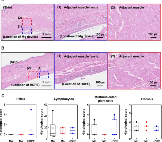
In vivo biocompatibility studies of bioresorbable device
Although the experiments described above reveal no signs of in-flammation or immune reactions, separate evaluations of bio-compatibility are useful. Tests for this purpose involve subdermal
implantation of Mg (group I) and Mo (group II) devices, each of which includes an encapsulation layer of PBTPA (1:4:7, ~100 m thick), a gate (3 mm by 3 mm) and counter electrode (Mg, 50 m thick; Mo, 10 m thick), and a PBTPA (1:4:7) reservoir (1 mm by 1 cm, ~900 m thick), in three groups of animals. A block of high- density polyethylene (HDPE; U.S. Food and Drug Administration– approved nontoxic material), with 1-mm thickness and 1 cm by 1 cm lateral dimensions similar to those of the test devices, serves as a control (group III). Here, electrochemical triggering uses a wired connection at 1 V for 5 min, performed shortly after subdermal im-plantation. The devices remain implanted for 5 weeks after removal of the wired connection. Hematoxylin and eosin images of stained tissue sections collected after this period appear in Fig. 7 (A and B) and figs. S19 and S20. The metal components undergo dissolution and bioresorption within this time. Some minimal inflammatory response and fibrosis appear in close proximity to the implants, but no significant evidence of injury or damage occurs at the adjacent tissue and muscle layers. Additional evaluations involve careful examination of each hematoxylin and eosin slide for the presence of acute and chronic inflammation, granulation tissue formation, and fibrosis. OM images [high-power field (HPF; 40× objective] at the highest density of inflammation yield counts of neutrophils, lym-phocytes, and giant cells (Fig. 7C). Presence or absence of granulation
Fig. 7. In vivo biocompatibility studies. Hematoxylin and eosin images of stained tissue sections at 5 weeks after implantation of (A) devices and (B) samples of
HDPE. Middle and right images show adjacent muscle fascia and muscle tissue, respectively. (C) Evaluations of histological scoring for reference controls (HDPE) and test groups (Mg metal gate and Mo metal gate devices) (n = 3 per group). PMN, polymorphonuclear. Boxplots show the median (center line), the third and first quartiles (upper and lower edge of box, respectively), and the largest and smallest value that is ≤1.5 times the interquartile range (limits of upper and lower whiskers, respectively). Photo credit: Matthew MacEwan, Washington University in St. Louis.
on April 27, 2021
http://advances.sciencemag.org/
tissue can be scored as absent, focal, or diffuse. Fibrosis scores on the Masson stain use were as follows: none = 0, mild = 1, moder-ate = 2, and severe = 3, as in Fig. 7. Measurements of weight change at 5 weeks after implantation show no significant differences (fig. S21). Counts of white blood cells in peripheral blood serum by cytometric bead arrays also indicate no significant differences be-tween groups (fig. S22). These results, together with previously reported findings, provide strong evidence of the biocompatibility of the individual constituent materials used in the platforms pre-sented here, such as PLGA (35), Mg (36), Mo (37), Si NM (20) and their use in other types of devices (14).
In summary, wirelessly programmable, battery-free drug delivery systems constructed entirely of bioresorbable materials represent a versatile class of technology for targeted pharmacologic treatment across a range of applications. The efficient containment and the en-gineered reservoir approach facilitate application to broad classes of pharmaceuticals, including proteins and hormones. Additional op-portunities are in cocktail therapies and controlled pharmacokinetics enabled by multiple, independently controlled reservoirs. The de-velopment of advanced approaches based on chip-based microcon-trollers to scale the number of reservoirs significantly beyond those of the systems presented here represents a direction for future work. These schemes enable long-term delivery and precise dosing if im-plemented with reservoirs that have individual volumes below a therapeutic concentration.
MATERIALS AND METHODS
Preparation of wireless, bioresorbable drug release vehicles
Preparation of the materials began with mixing of 4-PA, TTT, and 1,4-butanedithiol with a molar ratio of 1:4:7 (PBTPA 1:4:7) or 1:1:2.5 (PBTPA 1:1:2.5) in polydimethylsiloxane (PDMS) molds. Initiating a thiol-ene click reaction by adding photoinitiator (5 weight %) and exposing to UV light ( = 365 nm) formed PBTPA for the bio-resorbable reservoirs (13). Wet etching of foils (Mg foil, 10 to 50 m thick; or Mo foil, 10 m thick) yielded bioresorbable metal electrodes. An uncured layer of PBTPA bonded a film of PBTPA (50 m thick) with holes defined by a laser cutting process onto the metal elec-trodes. Exposure to UV light (4 W, = 365 nm) for 10 min com-pletely cured the entire structure. The extended metal electrodes were connected to a wireless stimulator unit built using a RF receiv-er coil of Mg, an RF diode constructed using a Si NM, and a parallel-
plate capacitor in a multilayer stack of Mg/SiO2/Mg. Biodegradable
conductive paste (Candelilla wax/W powder) electrically connected the individual components (14).
Measurements of permeability of drugs through constituent materials
A 1-cm-thick slab of PDMS (Sylgard 184, Dow Corning, USA) cast in a well structure served as a test vehicle for assessing permeation of aqueous solutions of drugs through layers of materials used in the devices (fig. S11). Mg (50 m thick), Mo (10 m thick), or PBTPA (1:4:7, 100 m) served as seals on the top of the PDMS well, bonded using an epoxy (LOCTITE EPOXY, Henkel Corp., USA). A syringe injection process delivered a drug solution (1 ml) through the side wall of the well. Sealing this injection location with epoxy prevented leakage. A coating of epoxy covered the entire system, including the side and back wall surfaces of the PDMS, to securely bond the test film in a vial filled with PBS (10 ml) and held at body
tempera-ture (37°C) for 30 days. At regular time intervals, samples of PBS (3 ml) collected from the vial were transferred to a cuvette for UV-vis spectroscopy. An absorption peak at 485 nm in the UV-vis spectrograms (UV-2450, Shimadzu Corp., Japan) allowed deter-mination of the concentration of doxorubicin, as described previ-ously (30). After each measurement, the PBS was returned to the original vial.
In vitro demonstration and evaluation of cell (NIH-3T3, MDA-MB-231, HepG2, and HeLa) viability
NIH-3T3 fibroblasts were cultured in DMEM (Gibco-BRL, USA) supplemented with 10% (v/v) fetal bovine serum (Gibco-BRL) and penicillin-streptomycin (100 U/ml; Gibco-BRL). The relative num-bers of live cells were determined using a CCK-8 according to the manufacturer’s protocol (n = 3 per group). MDA-MB-231, NIH-3T3, and HepG2 cells treated with the device, electrical trigger, and/or doxorubicin were imaged using an OM. The cells were fixed, per-meabilized, and subsequently incubated with Alexa Fluor 488– phalloidin (Molecular Probes) and DAPI (Sigma-Aldrich) to stain cell actin and nucleus, respectively. Imaging used a laser scanning confocal microscope (LSM 710, Zeiss). Phalloidin staining of cell actins enabled examination of the effects on cell adhesion.
EIS measurements of corrosion processes
Gates of Mg and Mo with circular shapes (radii of 1, 1.2, 1.4, 1.6, and 1.8 mm) defined by PBTPA (1:4:7) were submerged in an electro-chemical cell at room temperature with PBS as the electrolyte and with a counter electrode of Cu and a reference electrode of Ag/ AgCl. The corrosion followed from application of potentials at 0.5 to 5 V for 0.5 to 5 min using a potentiostat (Metrohm Autolab B.V., The Netherlands). The polarization measurements involved a scan rate of 1 mV/s and a scanning range from −1 to 1 V.
Electromagnetic simulation
Finite-element analysis yielded the scattering parameters (S11), the inductance (L), and the Q factor (Q) of the Mg RF coil with a match-ing capacitor. The simulations (Ansys HFSS 13 User’s Guide, Ansys Inc., 2011) used a lumped port to define the S11 and the port impendence (Z). An adaptive mesh (tetrahedron elements) ensured
computational accuracy, to yield L = ZIm/(2f) and Q = |ZIm/ZRe|,
where ZRe, ZIm, and f represent the real and imaginary parts of Z and
the frequency, respectively. A transmission coil (80 mm diameter, 3 turns, and winding with 1.6-mm diameter copper wire) added to the simulation model yielded a relationship between the power trans-fer efficiency and operating voltage.
In vivo demonstration of wirelessly triggered lidocaine release for sciatic nerve block
Male mice (30 g; C57BL/6J, the Jackson laboratory, USA) were anesthetized using isoflurane gas (3% for induction and 2% for maintenance) during surgical implantation of a bioresorbable drug delivery reservoir onto the right sciatic nerve of the animal. After the implantation, the surgical wound was closed with 8-0 Vicryl sutures and Autoclip wound clips (12020-09, Fine Science Tools). A signal generator (3390, Keithley, USA) and a high-frequency amplifier (8447E, Agilent, USA) provided RF power to a transmitter coil (80 mm diameter, 3 turns) placed over the implantation site to wirelessly power the implanted drug delivery device. After triggering the Mg metal gate for 5 min and release of lidocaine (Xylocaine-MPF 1%,
on April 27, 2021
http://advances.sciencemag.org/
Fresenius USA), CMAP (black) and SNAP (red) were measured (data are means ± SD; n = 3) with 1″ length, 0.30-mm diameter concen-tric needle electrodes (S53153 TECA, USA) on a VikingQuest EMG system using Synergy master software (982A0386, Natus, USA).
In vitro insulin release
Here, devices with insulin solution (0.9 IU diluted in 0.2 ml of PBS) and various metal gate sizes (1 mm by 1 mm to 5 mm by 5 mm) were triggered in a 25-ml vial filled with 10 ml of PBS solution. Small volumes (3 ml) of solution collected from different devices and vials for each time point were transferred in an insulating box (~2°C, within 24 hours) to the Diabetes Research Center at Washington University in St. Louis for measurements of the con-centration of insulin.
In vivo demonstration of wirelessly triggered insulin release from systems with multiple reservoirs
Male Lewis rats (300 g; Charles River Laboratories) were anesthetized using isoflurane gas (4% for induction and 2% for maintenance) during surgical implantation of a bioresorbable drug delivery reser-voir into a subcutaneous pocket in the back area of the animal. After implantation, the surgical wound was closed with 4-0 nylon sutures. A signal generator (3390, Keithley, USA) and a high- frequency amplifier (8447E, Agilent, USA) provided RF power to a transmit-ter coil (80 mm diametransmit-ter, 3 turns) placed over the implantation site to wirelessly power the implanted drug delivery device. After trig-gering the metal gate, blood glucose level monitoring was per-formed each hour over a time of 5 hours. A 23-gauge needle was used to prick the tip of the toe for blood sampling.
In vivo biocompatibility tests
Two types of devices [Mg gate device (group I, n = 3) and Mo gate device (group II, n = 3)] and a control group (group III, n = 3) were implanted in male Lewis rats (n = 9). All animal studies were performed in accordance with Institutional Animal Care and Use Committee at the Washington University in St. Louis. Male Lewis rats (300 g; Charles River Laboratories) were anesthetized using 4% isoflurane/96% oxygen (induction) and 2% isoflurane/98% oxygen (maintenance) administered by inhalation. Before implantation, test devices (Mg gate and Mo gate) and reference materials (HDPE) were sterilized by exposure to ethylene oxide. The devices were im-planted into a pocket created beneath the skin on the backs of the animals. Electrical triggering involved a wired connection at 1 V for 5 min to open the gates. After the triggering event, the device was implanted for 5 weeks with the wired connection removed. At the terminal time point, the animals were weighed (fig. S21), and venous blood was collected from the tail vein to assess for complete blood count and systemic toxicity (fig. S22). For histological analysis, the skin tissue and subcutaneous pockets containing the materials were excised and fixed in 10% neutral-buffered formalin, embedded in paraffin, and stained with hematoxylin and eosin.
Hematoxylin and eosin staining
Fixed skin samples were placed in a Tissue-Tek VIP 1000 tissue processor where they were submerged in graded alcohols followed by xylene and infiltration with paraffin. An embedding process formed paraffin blocks that were then sectioned on a Leica RM2125 RTS rotary microtome. The slides were deparaffinized and hydrated through graded alcohols. Staining used exposure to a modified Harris
hematoxylin (Richard-Allen Scientific, Kalamazoo, Michigan) for 2 min followed by differentiation in 0.1% acid alcohol and bluing in 0.1% ammonia water. After two rinses in 95% ethyl alcohol, samples were placed in an eosin Y with phloxine (Richard-Allen Scientific, Kalamazoo, Michigan) for 30 s. The samples were then dehydrated, cleared, and mounted.
Toluidine blue staining
The slides were deparaffinized and hydrated through graded alco-hols to water. The slides were then placed in 0.1% aqueous toluidine blue O (Allied Chemical, Rochester, NY) solution for 10 min. After rinsing in tap water, the samples were dehydrated quickly through 95 and 100% ethyl alcohol. This step was closely monitored to yield the correct amount of differentiation. The slides were then cleaned in xylene and mounted.
Histological scoring
A pathologist (M.P.) performed the histologic evaluation of the tissue at the Northwestern University, Feinberg School of Medicine. Each hematoxylin and eosin slide was carefully reviewed for the presence of acute and chronic inflammation, granulation tissue formation, and fibrosis. Neutrophils, lymphocytes, and giant cells were counted in a representative HPF (40× objective) with the highest density of inflammation. Presence or absence of granulation tissue was scored as absent, focal, or diffuse. Fibrosis was scored on a Masson stain as none = 0, mild = 1, moderate = 2, and severe = 3.
SUPPLEMENTARY MATERIALS
Supplementary material for this article is available at http://advances.sciencemag.org/cgi/ content/full/6/35/eabb1093/DC1
View/request a protocol for this paper from Bio-protocol.
REFERENCES AND NOTES
1. Q. Yao, Y. Liu, B. Selvaratnam, R. T. Koodali, H. Sun, Mesoporous silicate nanoparticles/3D nanofibrous scaffold-mediated dual-drug delivery for bone tissue engineering. J. Control. Release 279, 69–78 (2018).
2. M. L. Macdonald, R. E. Samuel, N. J. Shah, R. F. Padera, Y. M. Beben, P. T. Hammond, Tissue integration of growth factor-eluting layer-by-layer polyelectrolyte multilayer coated implants. Biomaterials 32, 1446–1453 (2011).
3. H. K. Makadia, S. J. Siegel, Poly lactic-co-glycolic acid (PLGA) as biodegradable controlled drug delivery carrier. Polymers 3, 1377–1397 (2011).
4. M. A. Luzuriaga, D. R. Berry, J. C. Reagan, R. A. Smaldone, J. J. Gassensmith, Biodegradable 3D printed polymer microneedles for transdermal drug delivery. Lab Chip 18, 1223–1230 (2018).
5. R. Farra, N. F. Sheppard Jr., L. McCabe, R. M. Neer, J. M. Anderson, J. T. Santini Jr., M. J. Cima, R. Langer, First-in-human testing of a wirelessly controlled drug delivery microchip. Sci. Trans. Med. 4, 122ra121 (2012).
6. M. Staples, K. Daniel, M. J. Cima, R. Langer, Application of micro- and nano-electromechanical devices to drug delivery. Pharm. Res. 23, 847–863 (2006). 7. Y. Zhang, D. C. Castro, Y. Han, Y. Wub, H. Guo, Z. Weng, Y. Xue, J. Ausra, X. Wang, R. Li,
G. Wu, A. Vázquez-Guardadom, Y. Xie, Z. Xie, D. Ostojich, D. Peng, R. Sun, B. Wang, Y. Yu, J. P. Leshock, S. Qu, C.-J. Su, W. Shen, T. Hang, A. Banks, Y. Huang, J. Radulovic, P. Gutruf, M. R. Bruchas, J. A. Rogers, Battery-free, lightweight, injectable microsystem for in vivo wireless pharmacology and optogenetics. Proc. Natl. Acad. Sci. 116, 21427–21437 (2019). 8. H. Tao, S.-W. Hwang, B. Marellia, B. An, J. E. Moreaua, M. Yang, M. A. Brenckle, S. Kim,
D. L. Kaplana, J. A. Rogers, F. G. Omenetto, Silk-based resorbable electronic devices for remotely controlled therapy and in vivo infection abatement. Proc. Natl. Acad. Sci. U.S.A. 111, 17385–17389 (2014).
9. C. H. Lee, H. Kim, D. V. Harburg, G. Park, Y. Ma, T. Pan, J. S. Kim, N. Y. Lee, B. H. Kim, K.-I. Jang, S.-K. Kang, Y. Huang, J. Kim, K.-M. Lee, C. Leal, J. A. Rogers, Biological lipid membranes for on-demand, wireless drug delivery from thin, bioresorbable electronic implants. NPG Asia Mat. 7, e227 (2015).
on April 27, 2021
http://advances.sciencemag.org/
10. J. Lee, H. R. Cho, G. D. Cha, H. Seo, S. Lee, C.-K. Park, J. W. Kim, S. Qiao, L. Wang, D. Kang, T. Kang, T. Ichikawa, J. Kim, H. Lee, W. Lee, S. Kim, S.-T. Lee, N. Lu, T. Hyeon, S. H. Choi, D.-H. Kim, Flexible, sticky, and biodegradable wireless device for drug delivery to brain tumors. Nat. Commun. 10, 5205 (2019).
11. S. N. Goldberg, G. D. Girnan, A. N. Lukyanov, M. Ahmed, W. L. Monsky, G. S. Gazelle, J. C. Huertas, K. E. Stuart, T. Jacobs, V. P. Torchillin, E. F. Halpern, J. B. Kruskal, Percutaneous tumor ablation: Increased necrosis with combined radio-frequency ablation and intravenous liposomal doxorubicin in a rat breast tumor model. Radiology 222, 797–804 (2002).
12. S. Dromi, V. Frenkel, A. Luk, B. Traughber, M. Angstadt, M. Bur, J. Poff, J. Xie, S. K. Libutti, K. C. Li, B. J. Wood, Pulsed-high intensity focused ultrasound and low temperature–sensitive liposomes for enhanced targeted drug delivery and antitumor effect. Clin. Cancer Res. 13, 2722–2727 (2007).
13. Y. S. Choi, J. Koo, Y. J. Lee, G. Lee, R. Avila, H. Ying, J. Reeder, L. Hambitzer, K. Im, J. Kim, K.-M. Lee, J. Cheng, Y. Huang, S.-K. Kang, J. A. Rogers, Biodegradable polyanhydrides as encapsulation layers for transient electronics. Adv. Funct. Mater. 2020, 2000941 (2020). 14. J. Koo, M. R. MacEwan, S.-K. Kang, S. M. Won, M. Stephen, P. Gamble, Z. Xie, Y. Yan,
Y.-Y. Chen, J. Shin, N. Birenbaum, S. Chung, S. B. Kim, J. K. D. V. Harburg, K. Bean, M. Paskett, J. Kim, Z. S. Zohny, S. M. Lee, R. Zhang, K. Luo, B. Ji, A. Banks, H. M. Lee, Y. Huang, W. Z. Ray, J. A. Rogers, Wireless bioresorbable electronic system enables sustained nonpharmacological neuroregenerative therapy. Nat. Med. 24, 1830–1836 (2018).
15. D. R. Merrill, M. Bikson, J. G. Jefferys, Electrical stimulation of excitable tissue: Design of efficacious and safe protocols. J. Neurosci. Methods 141, 171–198 (2005). 16. B. A. Kehler, G. O. Ilevbare, J. R. Scully, Crevice corrosion stabilization and repassivation
behavior of alloy 625 and alloy 22. Corrosion 57, 1042–1065 (2001).
17. Y. S. Choi, J. Koo, J. A. Rogers, Inorganic materials for transient electronics in biomedical applications. MRS Bull. 45, 103–112 (2020).
18. E. Song, Y. K. Lee, R. Li, J. Li, X. Jin, K. J. Yu, Z. Xie, H. Fang, Y. Zhong, H. Du, J. Zhang, G. Fang, Y. Kim, Y. Yoon, M. A. Alam, Y. Mei, Y. Huang, J. A. Rogers, Transferred, ultrathin oxide bilayers as biofluid barriers for flexible electronic implants. Adv. Funct. Mater. 28, 1702284 (2017).
19. L. Yin, H. Cheng, S. Mao, R. Haasch, Y. Liu, X. Xie, S.-W. Hwang, H. Jain, S.-K. Kang, Y. Su, R. Li, Y. Huang, J. A. Rogers, Dissolvable metals for transient electronics. Adv. Funct. Mater. 24, 645–658 (2014).
20. S.-W. Hwang, G. Park, C. Edwards, E. A. Corbin, S.-K. Kang, H. Cheng, J.-K. Song, J.-H. Kim, S. Yu, J. Ng, J. E. Lee, J. Kim, C. Yee, B. Bhaduri, Y. Su, F. G. Omennetto, Y. Huang, R. Bashir, L. Goddard, G. Popescu, K.-M. Lee, J. A. Rogers, Dissolution chemistry
and biocompatibility of single-crystalline silicon nanomembranes and associated materials for transient electronics. ACS Nano 8, 5843–5851 (2014).
21. S.-K. Kang, S.-W. Hwang, H. Cheng, S. Yu, B. H. Kim, J.-H. Kim, Y. Huang, J. A. Rogers, Dissolution behaviors and applications of silicon oxides and nitrides in transient electronics. Adv. Funct. Mater. 24, 4427–4434 (2014).
22. K. Cho, H. W. Pickering, Demonstration of crevice corrosion in alkaline solution without acidification. J. Electrochem. Soc. 137, 3313–3314 (1990).
23. B. A. Shaw, P. J. Moran, P. O. Gartland, The role of ohmic potential drop in the initiation of crevice corrosion on alloy 625 in seawater. Corros. Sci. 32, 707–719 (1991).
24. J. E. B. Randles, Kinetics of rapid electrode reactions. Discuss. Faraday Soc. 1, 11–19 (1947). 25. S. J. Xia, R. Yue, R. G. Rateick Jr., V. I. Birss, Electrochemical studies of AC/DC anodized Mg
alloy in NaCl solution. J. Electrochem. Soc. 151, B179–B187 (2004).
26. Y. Guo, Y. Su, S. Jia, G. Sun, R. Gu, D. Zhu, G. Li, J. Lian, Hydroxyapatite/titania composite coatings on biodegradable magnesium alloy for enhanced corrosion resistance, cytocompatibility and antibacterial properties. J. Electrochem. Soc. 14, C962–C972 (2018). 27. S. V. Gnedenkov, S. L. Sinebryukhov, D. V. Mashtalyar, K. V. Nadaraia, A. S. Gnedenkov,
V. M. Bouznik, Composite fluoropolymer coatings on the MA8 magnesium alloy surface. Corros. Sci. 111, 175–185 (2016).
28. D. R. Lide, Handbook of Chemistry and Physics (CRC Press, ed. 93, 2012). 29. G. Baril, G. Galicia, C. Deslouis, N. Pébère, B. Tribollet, V. Vivier, An impedance
investigation of the mechanism of pure magnesium corrosion in sodium sulfate solutions. J. Electrochem. Soc. 154, C108–C113 (2007).
30. X. Shuai, H. Ai, N. Nasongkla, S. Kim, J. Gao, Micellar carriers based on block copolymers of poly(-caprolactone) and poly(ethylene glycol) for doxorubicin delivery. J. Control. Release 98, 415–426 (2004).
31. R. Colombo, I. Dalle Donne, A. Milzani, Metal ions modulate the effect of doxorubicin on actin assembly. Cancer Biochem. Biophys. 11, 217–226 (1990).
32. P. V. Röder, B. Wu, Y. Liu, W. Han, Pancreatic regulation of glucose homeostasis. Exp. Mol. Med. 48, e219 (2016).
33. S. E. I. van der Wal, S. A. S. van den Heuvel, S. A. Radema, B. F. M. van Berkum, M. Vaneker, M. A. H. Steegers, G. J. Scheffer, K. C. P. Vissers, The in vitro mechanisms and in vivo efficacy of intravenous lidocaine on the neuroinflammatory response in acute and chronic pain. Eur. J. Pain 20, 655–674 (2016).
34. E. Marban, T. Yamagishi, G. F. Tomaselli, Structure and function of voltage-gated sodium channels. J. Physiol. 508, 647–657 (1998).
35. A. Srinivasan, M. Tahilramani, J. T. Bentley, R. K. Gore, D. C. Millard, V. J. Mukhatyar, A. Joseph, A. S. Haque, G. B. Stanley, A. W. English, R. V. Bellamkond, Microchannel-based regenerative scaffold for chronic peripheral nerve interfacing in amputees. Biomaterials 41, 151–165 (2015).
36. X. Gu, Y. Zheng, Y. Cheng, S. Zhong, T. Xi, In vitro corrosion and biocompatibility of binary magnesium alloys. Biomaterials 30, 484–498 (2009).
37. M. J. Akhtar, M. Ahamed, H. A. Alhadlaq, A. Alshamsan, M. A. Majeed Khan, S. A. Alrokayan, Antioxidative and cytoprotective response elicited by molybdenum nanoparticles in human cells. J. Colloid Interface Sci. 457, 370–377 (2015).
Acknowledgments: The authors specially thank J. Park for the help in analysis of cell test and imaging. Funding: J.Ko. acknowledges the support from the National Research Foundation of Korea (NRF-2020R1F1A1068083). Z.X. acknowledges the support from the Fundamental Research Funds for the Central Universities [grant no. DUT20RC(3)032]. X.F. acknowledges the support from the National Basic Research Program of China (grant no. 2015CB351900) and the National Natural Science Foundation of China (grant no. 11320101001). H.K and C.L. are partially supported by the NIH under grant no. 1DP2EB024377-01. Y.S.O and I.P are supported by the National Research Foundation of Korea (NRF) grant funded by the Korea Government (MSIT) (no. 2018R1A2B200491013). H.M.L is supported by the National Research Foundation of Korea (NRF) grant funded by the Korea government (NRF-2017R1E1A1A03071049). Y.H. acknowledges the support from NSF (grant no. 1635443). S.-K.K is supported by the National Research Foundation of Korea (NRF) grant funded by the Korea government (MSIT) (NRF-2019R1C1C1004232). J.A.R. acknowledges support from the Center for Bio-Integrated Electronics at Northwestern University. Author contributions: J.Ko., S.-K.K., M.M., and J.A.R. designed the research. J.Ko., Y.S.C., S.B.K., Z.X., J.Kh., Y.Y., H.K., M.K.P., K.D., G.L., D.D., Y.-Y.C., S.M.L., K.Li., S.J., H.W., J.-H.K., W.J.J., and J.-H.P. conducted in vitro and in vivo experiments. Z.X., K.Li., H.W., X.F., and Y.H. conducted the structural designs and electromagnetic modeling. J.Ko., Y.S.C., S.B.K., H.K., A.J.B., Z.X., K.J., K.Le.., J.Ki., S.-G.C., G.L., Y.S.O., I.P., S.S.K., X.F., C.-H.L., A.B., C.L., D.H., H.M.L., Y.H., C.K.F., W.Z.R., M.M., S.-K.K., and J.A.R. discussed and interpreted the data. J.Ko., Y.S.C., S.B.K., A.J.B., M.M., S.-K.K., and J.A.R. wrote the manuscript, and all authors revised it. D.D. conducted animal surgery to demonstrate drug release in mouse model. Competing interests: The authors declare that they have no competing interests. Data and materials availability: All data needed to evaluate the conclusions in the paper are present in the paper and/or the Supplementary Materials. Additional data related to this paper may be requested from the authors.
Submitted 30 January 2020 Accepted 17 July 2020 Published 28 August 2020 10.1126/sciadv.abb1093
Citation: J. Koo, S. B. Kim, Y. S. Choi, Z. Xie, A. J. Bandodkar, J. Khalifeh, Y. Yan, H. Kim, M. K. Pezhouh, K. Doty, G. Lee, Y.-Y. Chen, S. M. Lee, D. D'Andrea, K. Jung, K. Lee, K. Li, S. Jo, H. Wang, J.-H. Kim, J. Kim, S.-G. Choi, W. J. Jang, Y. S. Oh, I. Park, S. S. Kwak, J.-H. Park, D. Hong, X. Feng, C.-H. Lee, A. Banks, C. Leal, H. M. Lee, Y. Huang, C. K. Franz, W. Z. Ray, M. MacEwan, S.-K. Kang, J. A. Rogers, Wirelessly controlled, bioresorbable drug delivery device with active valves that exploit electrochemically triggered crevice corrosion. Sci. Adv. 6, eabb1093 (2020).
on April 27, 2021
http://advances.sciencemag.org/
Hyuck Mo Lee, Yonggang Huang, Colin K. Franz, Wilson Z. Ray, Matthew MacEwan, Seung-Kyun Kang and John A. Rogers Suk Oh, Inkyu Park, Sung Soo Kwak, Ji-Hyeon Park, Doosun Hong, Xue Feng, Chi-Hwan Lee, Anthony Banks, Cecilia Leal, KunHyuck Lee, Kan Li, Seongbin Jo, Heling Wang, Jae-Hwan Kim, Jeonghyun Kim, Sung-Geun Choi, Woo Jin Jang, Yong Maryam Kherad Pezhouh, Karen Doty, Geumbee Lee, Yu-Yu Chen, Seung Min Lee, Dominic D'Andrea, Kimin Jung,
DOI: 10.1126/sciadv.abb1093 (35), eabb1093. 6
Sci Adv
ARTICLE TOOLS http://advances.sciencemag.org/content/6/35/eabb1093
MATERIALS
SUPPLEMENTARY http://advances.sciencemag.org/content/suppl/2020/08/24/6.35.eabb1093.DC1
REFERENCES
http://advances.sciencemag.org/content/6/35/eabb1093#BIBL This article cites 36 articles, 6 of which you can access for free
PERMISSIONS http://www.sciencemag.org/help/reprints-and-permissions
Terms of Service Use of this article is subject to the
is a registered trademark of AAAS.
Science Advances
York Avenue NW, Washington, DC 20005. The title
(ISSN 2375-2548) is published by the American Association for the Advancement of Science, 1200 New
Science Advances
License 4.0 (CC BY-NC).
Science. No claim to original U.S. Government Works. Distributed under a Creative Commons Attribution NonCommercial Copyright © 2020 The Authors, some rights reserved; exclusive licensee American Association for the Advancement of
on April 27, 2021
http://advances.sciencemag.org/