교량상부에 부착된 구조물의 동적거동해석
Dynamic Evaluation of Bridge Mounted Structures
김 동 주*∙이 완 수**∙양 종 호*** Kim, Dongjoo∙Lee, Wansoo∙Yang, Jongho 1)
Summary
The design requirement for ground mounted sign structures are fairly well defined in the AASHTO Standard Specifications for Structural Supports for Highway Signs, Luminaries, and Traffic Signals and consists of applying an equivalent pseudo-dynamic loading to account for the dynamic effects of wind loads and ignores the dynamic effect due to moving vehicle loads. This design approach, however, should not be applied to the design of bridge mounted sign structures because ignoring the dynamic effects of the moving vehicle loads may produce non-conservative results, since the stiffness of the bridge structure can greatly influence the behavior. Not enough information is available in the literatures which provide guide lines to include the influence of moving vehicles in the design of the bridge mounted sign structures. This paper describes a theoretical methodology, Bridge-Vehicle Interaction Element, which can be utilized to account for the dynamic effect of moving vehicles. A case study is also included where this methodology was successfully applied.
It was concluded that the bridge-vehicle interaction finite element developed can provide a more accurate representation of the behavior of bridge mounted sign structures. The result of these analysis enabled development of simple and effective retrofitting scheme for the existing support system of bridge-mounted-structure.
keywords : Dynamic Evaluation, Simulation, Modified Newmark-β-Method
1. Introduction
The dynamic response of the bridge due to moving vehicle was studied by many researchers. As a result, various methods were developed. In the earlier study, the vehicle was modeled as moving load in which mass and suspension system of vehicle were ignored. Later, mass of vehicle was included and partial interaction between bridge and moving vehicle was accounted. As the practical approach, various numerical methods were developed. There are three types of numerical methods which are master–slaver method, dynamic-condensation method and Newmark’s beta method. In this paper, conventional Newmark β-method are modified to accommodate the behavior of bridge-vehicle interaction. As practical example,
** Samsung C&T∙토목기술실 교량구조파트 (차장) [email protected]
* ** Samsung C&T∙토목기술실 도로철도팀 (파트장) [email protected]
** Samsung C&T∙토목기술실 교량구조파트 부장(파트장) [email protected]
a failure of existing camera mounted system was investigated by using developed bridge-vehicle interaction element.
2. Equation of Motion
The behavior of bridge-mounted structure, exited by moving vehicle, can be modeled by two sets of systems; the vehicle and bridge system as shown in Figure 1.
Figure 1 Idealized bridge and vehicle model
By using the matrix method with an incremental form, the systems shown in Figure 1 can be expressed as two sets of equation of motion. The first equation, EQ (1), is for the moving vehicle in which two nodes were used for representing the upper and lower part of vehicle.
1 0 0 1 2 1 1 2 1 1 2 1 2 0 0 1 t c f W t d d k k k k t d d c c c c t d d m m
⎭
⎬
⎫
⎩
⎨
⎧
⎭
⎬
⎫
⎩
⎨
⎧
⎭
⎬
⎫
⎩
⎨
⎧
⎥⎦
⎤
⎢⎣
⎡
⎭
⎬
⎫
⎩
⎨
⎧
⎥⎦
⎤
⎢⎣
⎡
⎭
⎬
⎫
⎩
⎨
⎧
⎥⎦
⎤
⎢⎣
⎡
+ − = − − + − − + && && && (1) where m, c and k are the mass, damping coefficient and spring constant of vehicle element. d is displacement. It should be noted that only vertical displacement was considered as the acting degree of freedom in this analysis. The subscript of d (1, 2) are represent nodes at upper and lower part of truck. The fc is contact force generated from interaction between bridge and vehicle. W is the weight of vehicle. t1 is the time at current stage. By using Newmark's β-method and incremental steps, the contact force, fc, can be obtained as EQ (2).( )
d t Wc c k t d c c t d c m c f = ⎛⎝⎜ &&2⎟⎠⎞1+ ⎛⎝⎜&2⎞⎠⎟1+ 2 1+ .( )
( )
(
) (
)
( )
(
)
( )
(
)
( )
( )
t a t a a t a t a k c t d c c m c a t d m c a t d W c W k c a m a k c a c k c c k c c c c m c m Δ = Δ = − = Δ = Δ = Γ − + ⎟ ⎠ ⎞ ⎜ ⎝ ⎛ −Γ − Γ + Γ + = − + + − − = Γ Γ + = Γ + = = 2 4 , 2 3 , 1 2 1 2 , 1 1 , 2 1 0 1 0 1 1 1 0 1 2 0 1 1 4 0 4 , 1 , 1 , 2 β β β & && (2)The motion of bridge can be expressed as EQ (3).
[ ]
{ }
[ ]
{ }
[ ]
{ }
d t{ }
fb b k t b d b c t b d b m + + 1 = 1 1 & & & (3)where [mb], [cb] and [kb] are mass, damper and stiffness matrix of the bridge. Since the contact
Spring Mass Damper mT kT cT mB
Moving Mass
M
Moving Load P Vehicle model Bridgespring damper model moving load model moving mass model
Vehicle model Vehicle model
Figure 1 Idealized bridge and vehicle model
force, as shown in EQ (2), is an external force loaded on bridge element, equivalent nodal load for the contact force can be obtained by using shape function; thus EQ (2) and EQ (3) are combined as EQ (4).
( ) { }
( ) { }
( ) { }
{ }
{ } { }
[ ]
{ }
[ ]
{ }
[ ]
{ }
( ) ( )
( ) ( )
1 0( ) ( )
1 0( ) ( )
1 0 0 1,
,
, 0 0 0 1 1 1 t n t n t n t n t n t n t n t nc
c
c
k
k
k
m
m
m
W
W
W
t b d k t b d c t b d m W F F b d t n c b c b d t n c b c b d t n m b m−
=
Δ
−
=
Δ
−
=
Δ
−
=
Δ
⎥⎦
⎤
⎢⎣
⎡
⎥⎦
⎤
⎢⎣
⎡
⎥⎦
⎤
⎢⎣
⎡
Δ + Δ + Δ + Δ = Δ Δ = Δ + + Δ + + Δ + & && & && (4)The displacement, db in EQ (4), can be obtained by using incremental time step, Newmark β-method
and assumption that the unbalance on vehicle properties (mass, stiffness and damping) due to moving location are small and can be neglected.
{ }
[ ]
( )
( ) { }
( ) { }
{ }
( )
( )
( )
{ } ( )
(
)
( )
{ } ( )
4( )
0 0 1 0 1 3 0 2 1 1 1 1 0 1 1 1 1 1 t b d a t b d a s R t b d a t b d a s Q t n k b k t n c b c a t n m b m a e K s R t n c b c s Q t n m b m t n W e K t b d && & && & + = + + = + + + + + = ⎥⎦ ⎤ ⎢⎣ ⎡ + + ⎥⎦ ⎤ ⎢⎣ ⎡ + + − =⎥⎦
⎤
⎢⎣
⎡
⎥⎦
⎤
⎢⎣
⎡
⎥⎦
⎤
⎢⎣
⎡
⎥⎦
⎤
⎢⎣
⎡
(5) 3. Calibration of ModelAs numerical solution of EQ (4), The Bridge-Vehicle interaction finite element were developed by using EQ (5). The calibration of developed element was done by campraison among the results of various case studies in the literature. An example, [Y.B. Yang], was selected, the moving vehicle traveled on the simple span. Figure 2 shows the result of comparison in which two (2) results are very close.
-0.0022 -0.0018 -0.0014 -0.0010 -0.0006 -0.0002 0.0002 0.0 0.2 0.4 0.6 0.8 1.0 Time(sec) D is pl acem ent .( m ) Moving Load-Present Moving Load-Y.B.Yang L=25m E=2.87GPa I=2.9m^4 m=2.303 t/m V=27.8 m/sec
Figure 2 Displacement at Midspan of Simple Span
4. The Dynamic Effect Due to Moving Vehicle
The camera support system mounted on the Bridge, Gowanus Expressway NY, was modeled by using the developed Vehicle-Bridge Interaction Element, and the dynamic effects due to moving vehicle was investigated. Figure 3 shows the 3D model of support system and results.
Figure 3 Dynamic Effect due to Vehicle Modeling and Moving Speed
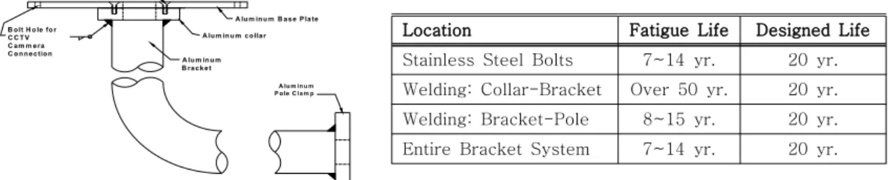
5. Evaluation of Fatigue Strength
The vertical and horizontal load due to the acceleration induced by the moving vehicle was applied to the camera support system mounted on the bridge. The Fatigue life of support are shown in Figure 3
A lu m in u m c o lla r A lu m in u m B a s e P la te 1 4 " S ta in le s s S te e l B o lt A lu m in u m B ra c k e t B o lt H o le fo r C C T V C a m m e ra C o n n e c tio n A lu m in u m P o le C la m p
Location Fatigue Life Designed Life Stainless Steel Bolts 7~14 yr. 20 yr. Welding: Collar-Bracket Over 50 yr. 20 yr. Welding: Bracket-Pole 8~15 yr. 20 yr. Entire Bracket System 7~14 yr. 20 yr.
Figure 3 Dynamic Effect due to Vehicle Modeling and Moving Speed
6. Summary and Conclusion
It was concluded that the bridge-vehicle interaction finite element developed can provide a more accurate evaluation of the behavior of bridge mounted sign structures. The dynamic effects on bridge mounted structure due to moving vehicle is significant, and ignoring the dynamic effects of the moving vehicle loads produces non-conservative results
Reference
AASHTO LRFD (2006) Standard Specification for Structural Supports for Higway Signs, Luminaries and Traffic Signals. Washington, D.C.
Y.B. Yang (2004) Vehicle-Bridge Interaction Dynamic. NY World Scientific.
John W. Fisher. (1984) Fatigue and Fracture in Steel Bridge. N.Y.: John Wiley & Son.
camera support