http://dx.doi.org/10.11142/jicems.2014.3.4.487 487 Journal of International Conference on Electrical Machines and Systems Vol. 3, No. 4, pp. 487~490, 2014
Analysis and Design of Separated Permanent-Magnet Actuator
for 225AF Molded Case Circuit Breaker
Hyeon-Jeong Park *, So-Hyun Kim *, Jong-Suk Ro **, and Hyun-Kyo Jung *
Abstract
– The conventional motor-driven MCCB (molded-case circuit breaker) is not only large in size, but also inefficient in performance. To solve these problems, this paper suggests SPMA (separate permanent-magnet actuator), a novel magnetic actuator. In this paper, SPMA is designed for a 225AF MCCB and compared to a conventional motor-driven MCCB and to an EMFA (electro-magnetic force driving actuator)-type MCCB.Keywords:
Molded case circuit breaker, Permanent-magnet actuator1. Introduction
In recent years, the level of demand for remote-controllable MCCBs (molded-case circuit breakers) has increased significantly due to the worldwide increase in smart grid projects.
The conventional MCCB is operated using mechanical components, such as a compressed spring and bimetal materials [1]. Hence, a mechanical MCCB cannot be controlled by electric signals. For controllability, an additional driving motor is necessary for the conventional MCCB. However, a motor-driven MCCB is inefficient in terms of performance while also being relatively large.
To address these problems, an MCCB which utilizes a SPAM (separate permanent-magnet actuator) is proposed in this paper.
The SPMA-type MCCB has superior properties compared to the motor-driven MCCB in terms of both size and efficiency, as the magnetic actuator operates the MCCB directly. Furthermore, the SPMA-type MCCB has the advantages of a convenient manufacturing process, high reliability, and a low cost because it minimizes the volume of PM (permanent-magnet) and simplifies the geometry.
The SPMA is analyzed and designed for a 225AF (ampere-frame) MCCB using an analysis and design method in which the correctness is verified through our previous research [2].
2. Structure and Working Principle of the SPMA
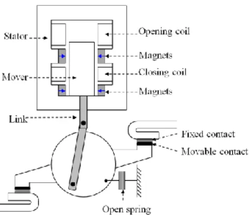
Fig. 1 shows the structure of the SPMA-type MCCB. The SPMA consists of a stator, a mover, coils, and magnets [3]. The stator and mover are made of bulk magnetic steel. When the coil is excited, the mover is moved into a position that minimizes the reluctance. The mover can remain in this position without consuming any power due to the magnets.In the open state, the mover is located on the top and contacts are separate from one another. In the closing state, the closing coil is excited in the open state, as shown in Fig. 2 (a). The mover is translated downward by the magnetic force of the closing coil and the movable contacts are connected to fixed contacts, thus compressing the open spring.
In the closed state, the mover is located on the bottom and the movable contacts are connected to the fixed contacts. To open, the opening coil is excited in the closed state, as shown in Fig. 2 (b). The mover is translated upward by magnetic force of the opening coil and the movable contacts are separate from the fixed contacts.
Fig. 1. Configuration of SPMA-type MCCB
* Dept. of Electrical & Computer Engineering, Seoul Nat'l University, Korea.
** Brain Korea 21 Plus Creative Research Engineer Development, Dept. of Electrical & Computer Engineering, Seoul Nat'l University, Korea. ([email protected])
Hyeon-Jeong Park, So-Hyun Kim, Jong-Suk Ro, and Hyun-Kyo Jung 488
(a) Closing (b) Opening Fig. 2. Working principle of SPMA-type MCCB
3. Analysis of SPMA
3.1 Static Magnetic Field AnalysisIn this paper, a 2D FEM (finite element method) is used for the static magnetic field analysis. The governing equation for the magnetic vector potential A (Wb/m2) is given by (1), ) ( ) ( A J0 0M (1)
where ν (m/H) denotes the reluctivity, J0 (A/m2) is the external current density vector, μ0 (H/m) is the permeability of the free space, and M (A/m) is the residual magnetization vector [4].
The magnetic force can be calculated using the stress tensor method [5].
B nB BndS F s mag
2 0 0 2 1 1 (2)Here, B (T) is the magnetic flux density, s (m2) is the area of the mover and n is the normal vector of the surface of the mover. In addition, the linkage flux λ (Wb) can be calculated by (3).
A dl (3) where A (Wb/m) is the magnetic vector potential and l (m) is the length of the coil.
3.2 Analysis of Circuit Equations
The equivalent circuits of each coil are shown in Fig. 3. For the closing operation, the closing coil is fed by a rectified AC source until the capacitor is fully charged, as illustrated in Fig. 3 (a). For the opening operation, the
capacitor, charged during the closing operation as mentioned above, supplies power to the opening coil, as shown in Fig. 3 (b).
(a) Closing coil
(b) Opening coil Fig. 3. Equivalent circuit
Applying Kirchhoff's law, the circuit equations for the closing coil and the opening coil can be derived by (4), and (5), respectively. c c s V dt x i d i R V (, ) (4) dt x i d i R Vc o ) , ( (5)
In these equations, Vs (V) is the rectified AC source, Rc (Ω) is the resistance of the closing coil, Ro (Ω) is the resistance of the opening coil, i (A) is the current of the closing coil, and Vc (V) is charged voltage of the capacitor.
However, the linkage flux cannot be expressed as one function because of non-linear property of magnetic steel. To take into account the non-linear property of magnetic steel, the TDM (time-differential method) has to be applied to these equations [5].
The modified circuit equations for closing coil and opening coil are shown in (6), and (7), respectively.
n c n n n n n s V dt x i d di i R V ( , ) ) ( 1 1 1 (6) dt x i d di i R V n n n n n c ) , ( ) ( 1 1 1 (7)
3.3 Analysis of Motion Equations
489 Analysis and Design of Separated Permanent-Magnet Actuator for 225AF Molded Case Circuit Breaker magnetic force and the spring force, as shown in (8).
Frictional forces and the gravitational force are negligible compared to the magnetic force and the spring force.
spr mag
net F F
F (8)
Here, Fnet is net force, Fmag is the total magnetic force, and Fspr is the spring force. Applying Newton's law and the TDM, the velocity and displacement of the mover can be derived by (9) and (10), respectively.
dt m F v vn n net 1 (9) 2 1 1 ( ) 2 1 dt m F dt v x xn n n net (10)
In the equation above, v is the velocity, m is the mass of the moving bodies, and x is the displacement.
4. Design and Analysis Results
4.1 Requirements of a 225AF MCCBA SPMA is designed for a 225AF MCCB. The requirements of the 225AF MCCB are summarized in Table 1.
The contact stroke is defined as the distance between the fixed contacts and the movable contacts. The holding force is the magnetic force generated by the magnets in the closed state or in the open state. The peak current is limited to 10 (A) on account of the cost of control devices.
Table 1. The requirements of 225AF MCCB
Contact stroke 9.6 (mm)
Pole number 4
Spring force 2.3 (kg/pole)
Contact mass 20 (g/pole)
Open holding force 150 (N)
Close holding force 110 (N)
Breaking time 17 (ms)
Source 220 (V), 60 (Hz)
Peak current 10 (A)
4.2 Design Results
The final design of the SPMA is illustrated in Fig. 4, and its parameters are listed in Table 2. All requirements are satisfied, and the volume of the SPMA is minimized.
The volume of the magnets of the designed SPMA is reduced significantly by 95% compared to an EMFA (electro-magnetic force driving actuator) [6]. The
conventional EMFA is operated by Lorentz force. Accordingly, the magnets must be arranged along the stroke in order to generate the required Lorentz force. On the other hand, the SPMA is operated by the reluctance force and the magnets are only required to produce the holding force. Thus, the volume and cost of the magnets could be decreased significantly.
Furthermore, the total volume of the SPMA-type MCCB is smaller than that of the motor-driven MCCB and the EMFA-type MCCB. As a result, the total size of the designed SPMA-type MCCB is reduced by 33% relative to the size of the motor-driving MCCB and by 17% relative to that of the EMFA-type MCCB.
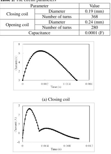
Fig. 4. Configuration of designed SPMA for 225AF MCCB Table 2. The circuit parameters
Parameter Value
Closing coil Diameter 0.19 (mm)
Number of turns 368
Opening coil Diameter 0.24 (mm)
Number of turns 280
Capacitance 0.0001 (F)
(a) Closing coil
(b) Opening coil
Hyeon-Jeong Park, So-Hyun Kim, Jong-Suk Ro, and Hyun-Kyo Jung 490 4.3 Analysis Results
Based on the analysis method, the SPMA is analyzed, as shown in Fig. 5. Fig. 5 presents the calculated current of the closing coil and the opening coil.
During the closing operation, the current initially increases. At 1.5 ms, the magnetic force generated from the coil is greater than the open holding force. Thus, the mover is translated and motional electromotive force is generated in the closing coil. Accordingly, the current of the closing coil is decreased until the capacitor is fully charged.
Similarly, the current is increased initially and is decreased after the mover starts to move into the open side during the opening operation. The opening operation finishes within 3 ms.
After the motion, the current of the opening coil is increased temporarily given that the motional electromotive force reaches zero.
5. Conclusion
The problems of a conventional motor-driving MCCB can be solved by applying the SPMA as introduced here. The SPMA has a remarkably small volume compared to conventional MCCBs. Moreover, the cost of the SPMA can be reduced by minimizing the volume of the magnets and by simplifying the manufacturing process. Accordingly, this paper contributes to the commercialization of MCCB through the novel application of a magnetic actuator.
Acknowledgements
This research was funded by KD Power.References
[1] X. Li, D. Chen, Y. Wang, Q. Wang, and Y. Geng, “Analysis of the interruption process of molded case circuit breakers,”
IEEE Transactions on Components and Packaging Technologies, vol. 30, no. 3, pp.375-382, September, 2007.
[2] D. J. Cho, D. K. Woo, J. S. Ro, T. K. Chung, and H. K. Jung, “Novel electromagnetic actuator using a permanent magnet and an inter-locking mechanism for a magnetic switch,”
IEEE Transactions on Magnetics, vol. 49, no. 5, pp.
2229-2232, May, 2013.
[3] J. S. Ro, S. K. Hong, and H. K. Jung, “Characteristic analysis and design of a novel permanent magnetic actuator for a vacuum circuit breaker,” IET Electric Power Applications, vol. 7, no. 2, pp. 87-96, February, 2013.
[4] D. K. Cheng, Field and eave electromagnetics, 1992. [5] J. H. Kang, H. K. Jung, “Dynamic behavior analysis of
permanent magnetic actuator in vacuum circuit breaker,” The
seventh International Conference on Electrical Machines and Systems (ICEMS), 2004.
[6] S. K. Hong, B. J. Bae, D. J. Cho, and H. K. Jung, “Design of Electromagnetic Force driving Actuator(EMFA) and linkage for Molded Case Circuit Breaker,” International Conference
on Electrical Machines and Systems (ICEMS), 2010. Hyeon-Jeong Park received B.S degree in electrical and electronics engineering from Chung-ang university, Seoul, Korea, in 2012. She is currently a Ph. D Candidate in Seoul National University, Seoul, Korea. Her research interests are analysis and design of the electric machinery.
So-Hyun Kim received B.S degree in electrical and Electronics engineering from Chung-ang University, Seoul, Korea, in 2013. She is currently a M.S. course in Seoul National University, Seoul, Korea. Her research interests are the analysis and design of the electric machine.
Jong-Suk Ro received a PhD in Electrical engineering from Seoul National University, Seoul, Korea, in 2008. In 2001, he received the B.S. degree in Mechanical Engineering from Han-Yang University, Seoul, Korea.
Currently, he is at Brain Korea 21 Plus, Creative Research Engineer Development, Seoul National University as a BK Assistant Professor. In 2014, he was with the University of Bath, Bath, UK. He carried out research at Electrical Energy Conversion System Research Division of Smart Grid Team at Korea Electrical Engineering & Science Research Institute as a Researcher in 2013. From 2012 to 2013, he was at Brain Korea 21 Information Technology of Seoul National University as a Post-Doctoral Fellow. He conducted research at R&D center of Samsung Electronics as a Senior Engineer from 2008 to 2012. His research interest is analysis and optimal design of electric machines and systems.
Hyun-Kyo Jung received the B.S., M.S., and Ph.D. degree in Electrical engineering from Seoul National University, Seoul, Korea, in 1979, 1981, and 1984, respectively. From 1985 to 1994, he was a member of the faculty with Kang-won National University. From 1987 to 1989, he was with the Polytechnic University of Brooklyn, Brooklyn, NY. From 1999 to 2000, he was a Visiting Professor with the University of California at Berkeley. He is currently a Professor at the School of Electrical Engineering and Computer Science/Electrical Engineering, Seoul National University. His research interests are the analysis and design of the electric machine.