Time multiplexing technique of holographic
view and Maxwellian view using a liquid lens
in the optical see-through head mounted
display
J
INS
UL
EE, Y
OOK
WANGK
IM,
ANDY
ONGH
YUBW
ON*School of Electrical Engineering, Korea Advanced Institute of Science and Technology, Daejeon 34141, South Korea
Abstract: We report a liquid lens based optical see-through head mounted display that can
simultaneously display both a maxwellian view and a hologram. Holograms are reconstructed by an angular spectrum layer based synthesis method. A hologram and Maxwellian view are simultaneously displayed by focusing the liquid lens from 0 D to 20 D with 60 Hz. The hologram is reconstructed at a position 1.5 m from the eye, and it is confirmed that the Maxwellian view is clear, even if the focus of the eye changes from 50 cm to 1.7 m. In the proposed system, the liquid lens acts as a low-pass filter. Since the PSNR is about 23 dB in the currently used 10 mm diameter liquid lens, the image quality is not adequate. However, we successfully verify the feasibility of our proposed system. In addition, if a large diameter liquid lens of 30 mm or more is applied, excellent image quality of 30 dB or more can be realized.
© 2018 Optical Society of America under the terms of the OSA Open Access Publishing Agreement
OCIS codes: (090.1760) Computer holography; (090.2820) Heads-up displays; (080.3620) Lens system design; (220.3630) Lenses.
References and links
1. Q. Gao, J. Liu, J. Han, and X. Li, “Monocular 3D see-through head-mounted display via complex amplitude modulation,” Opt. Express 24(15), 17372–17383 (2016).
2. S. Reichelt, R. Häussler, G. Fütterer, and N. Leister, “Depth cues in human visual perception and their realization in 3D display,” Proc. SPIE 7690(1), 76900B (2010).
3. S. K. Kim, D. W. Kim, Y. M. Kwon, and J. Y. Son, “Evaluation of the monocular depth cue in 3D displays,” Opt. Express 16(26), 21415–21422 (2008).
4. S. Park, J. Roh, S. Kim, J. Park, H. Kang, J. Hahn, Y. Jeon, S. Park, and H. Kim, “Characteristics of complex light modulation through an amplitude-phase double-layer spatial light modulator,” Opt. Express 25(4), 3469– 3480 (2017).
5. Z. Zeng, H. Zheng, Y. Yu, A. K. Asundi, and S. Valyukh, “Full-color holographic display with increased-viewing-angle [Invited],” Appl. Opt. 56(13), F112–F120 (2017).
6. Y. Z. Liu, X. N. Pang, S. Jiang, and J. W. Dong, “Viewing-angle enlargement in holographic augmented reality using time division and spatial tiling,” Opt. Express 21(10), 12068–12076 (2013).
7. Y. Takaki and M. Yokouchi, “Speckle-free and grayscale hologram reconstruction using time-multiplexing technique,” Opt. Express 19(8), 7567–7579 (2011).
8. Y. Mori, T. Fukuoka, and T. Nomura, “Speckle reduction in holographic projection by random pixel separation with time multiplexing,” Appl. Opt. 53(35), 8182–8188 (2014).
9. L. Golan and S. Shoham, “Speckle elimination using shift-averaging in high-rate holographic projection,” Opt. Express 17(3), 1330–1339 (2009).
10. A. Jesacher, S. Bernet, and M. Ritsch-Marte, “Broadband suppression of the zero diffraction order of an SLM using its extended phase modulation range,” Opt. Express 22(14), 17590–17599 (2014).
11. J. Liang, S. Y. Wu, F. K. Fatemi, and M. F. Becker, “Suppression of the zero-order diffracted beam from a pixelated spatial light modulator by phase compression,” Appl. Opt. 51(16), 3294–3304 (2012).
12. T. Shimobaba, H. Nakayama, N. Masuda, and T. Ito, “Rapid calculation algorithm of Fresnel computer-generated-hologram using look-up table and wavefront-recording plane methods for three-dimensional display,” Opt. Express 18(19), 19504–19509 (2010).
#313917 https://doi.org/10.1364/OE.26.002149 Journal © 2018 Received 21 Nov 2017; revised 11 Jan 2018; accepted 12 Jan 2018; published 19 Jan 2018
13. D. Arai, T. Shimobaba, K. Murano, Y. Endo, R. Hirayama, D. Hiyama, T. Kakue, and T. Ito, “Acceleration of computer-generated holograms using tilted wavefront recording plane method,” Opt. Express 23(2), 1740–1747 (2015).
14. J. L. Martinez, E. J. Fernandez, P. M. Prieto, and P. Artal, “Chromatic aberration control with liquid crystal spatial phase modulators,” Opt. Express 25(9), 9793–9801 (2017).
15. S. A. Goorden, J. Bertolotti, and A. P. Mosk, “Superpixel-based spatial amplitude and phase modulation using a digital micromirror device,” Opt. Express 22(15), 17999–18009 (2014).
16. Q. Gao, J. Liu, X. Duan, T. Zhao, X. Li, and P. Liu, “Compact see-through 3D head-mounted display based on wavefront modulation with holographic grating filter,” Opt. Express 25(7), 8412–8424 (2017).
17. G. Kramida, “Resolving the Vergence-Accommodation Conflict in Head-Mounted Displays,” IEEE Trans. Vis. Comput. Graph. 22(7), 1912–1931 (2016).
18. M. Waldkirch, P. Lukowicz, and G. Tröster, “Oscillating fluid lens in coherent retinal projection displays for extending depth of focus,” Opt. Commun. 253(4–6), 407–418 (2005).
19. H. Urey, S. Holmstrom, U. Baran, K. Aksit, M. K. Hedili, and O. Eides, “MEMS scanners and emerging 3D and interactive Augmented Reality display applications,” in 2013 Transducers & Eurosensors XXVII: The 17th International Conference on Solid-State Sensors, Actuators and Microsystems (2013), pp. 2485–2488. 20. D. W. Kim, Y. M. Kwon, Q. H. Park, and S. K. Kim, “Analysis of a head-mounted display-type multifocus
display system using a laser scanning method,” Opt. Eng. 50(3), 034006 (2011).
21. F. W. Campbell, “The depth of field of the human eye,” J. Mod. Opt. 4(4), 157–164 (1957).
22. A. Maimone, A. Georgiou, and J. S. Kollin, “Holographic near-eye displays for virtual and augmented reality,” ACM Trans. Graph. 36(4), 85 (2017).
23. R. Häussler, S. Reichelt, N. Leister, E. Zschau, R. Missbach, and A. Schwerdtner, “Large real-time holographic displays: from prototypes to a consumer product,” Proc. SPIE 7237, 72370S (2009).
24. R. Häussler, Y. Gritsai, E. Zschau, R. Missbach, H. Sahm, M. Stock, and H. Stolle, “Large real-time holographic 3D displays: enabling components and results,” Appl. Opt. 56(13), F45–F52 (2017).
25. H. Wei, G. Gong, and N. Li, “Improved look-up table method of computer-generated holograms,” Appl. Opt. 55(32), 9255–9264 (2016).
26. K. Matsushima and S. Nakahara, “Extremely high-definition full-parallax computer-generated hologram created by the polygon-based method,” Appl. Opt. 48(34), H54–H63 (2009).
27. Y. Zhao, L. Cao, H. Zhang, D. Kong, and G. Jin, “Accurate calculation of computer-generated holograms using angular-spectrum layer-oriented method,” Opt. Express 23(20), 25440–25449 (2015).
28. H. Zhang, L. Cao, and G. Jin, “Computer-generated hologram with occlusion effect using layer-based processing,” Appl. Opt. 56(13), F138–F143 (2017).
29. K. Matsushima and T. Shimobaba, “Band-Limited Angular Spectrum Method for Numerical Simulation of Free-Space Propagation in Far and Near Fields,” Opt. Express 17(22), 19662–19673 (2009).
30. T. Shimobaba, H. Yamanashi, T. Kakue, M. Oikawa, N. Okada, Y. Endo, R. Hirayama, N. Masuda, and T. Ito, “In-line digital holographic microscopy using a consumer scanner,” Sci. Rep. 3(1), 2664 (2013).
31. N. Hasan, H. Kim, and C. H. Mastrangelo, “Large aperture tunable-focus liquid lens using shape memory alloy spring,” Opt. Express 24(12), 13334–13342 (2016).
32. N. Hasan, A. Banerjee, H. Kim, and C. H. Mastrangelo, “Tunable-focus lens for adaptive eyeglasses,” Opt. Express 25(2), 1221–1233 (2017).
33. P. Zhao, Ç. Ataman, and H. Zappe, “Gravity-immune liquid-filled tunable lens with reduced spherical aberration,” Appl. Opt. 55(28), 7816–7823 (2016).
1. Introduction
Computer generated holograms are a useful and effective technology employed in various industrial fields [1]. They provide an environment similar to seeing real objects by reconstructing virtual objects in the air. Hologram displays are considered promising technology for the next generation 3D displays [2]. When someone see the object in the air, eyes collect several depth cues such as accommodation, binocular disparity, texture, color and motion parallax, etc. Conventional 3D display such as stereoscopic glasses, multiview, and integral imaging cannot provide all depth cue [3,4]. Basically, the hologram create voxels in the air by modulating complex amplitude of the light. Hence, the hologram in monocular vision, eye receive accommodation information from each voxels. Although computer generated holograms have progressed tremendously by advanced semiconductor technology, inevitable obstacles for commercialization remain, such as field of view (FOV) [5, 6], speckle noise [7–9], DC noise [10,11], a large processing load [12,13], etc. The hologram is an image reconstructed in space by controlling the complex amplitude of the light with spatial light modulators (SLMs) such as a liquid crystal on silicon (LCOS) [14, 16], a digital mirror device (DMD) [15], a transmissive liquid crystal panel [1], etc. Although SLM technology has been developed for decades, pixelate structure and large pixel pitch of the SLM cause image
quality related problems including FOV, exit pupil (Eye box), DC noise, and image resolution, as mentioned above. Recently, SLMs under several micron pixels have been released to overcome these issues, but they are not capable of creating large area high definition holograms. On the other hand, small area holograms can be reconstructed with sufficient resolution for augmented reality display and virtual reality displays. Recently, many studies related to hologram augmented reality and virtual reality head mount displays that can reconstruct high resolution and full color holograms have been presented [1,16].
Maxwellian view is a method of observation with extended depth of focus. If the light is focused on the entrance of the pupil, the eye will appear as a disc filled with light of uniform intensity [17]. Therefore, if the transparent screen is put into the system properly, the eye can see the image of the screen without accommodation. Hence, most accommodation-free displays use the maxwellian view principle [18,19]. As a typical example, a laser-MEMS-scanner based Maxwellian display has been suggested as an AR device [19,20]. Unlike hologram, the Maxwellian displays do not provide accomodation in monocular vision. Thus, observer receives only 2D images. Since the depth of focus is extremely large, it is always possible to provide clear images regardless of the eye's performance (diopters, aberrations, etc.).
Computer-generated holograms reconstruct realistic objects in the air, observer receives the 3D viewing experience and the 3D cues from the hologram. But, in this case, the eye only focuses on the small area due to the visual angle of the eye [21]. In other words, even if dozens of objects are created in the air, we can only see a small number of objects. Thus, in order to solve this hologram’s limitation, we combined the Maxwellian view with the holographic view, as the former provides clear images regardless of the focus of the eye. Our proposed display simultaneously provides both the holographic view and the Maxwellian view by 60Hz time multiplexing technique using a liquid lens. As far as we know, there has been no published research to synthesize both a hologram and a maxwellian view.
In this paper, we verify the feasibility of an optical see-through head mounted display that time multiplexed expresses both a hologram and the maxwellian view using a liquid lens. Although all experiments are done on an optical table rather than with a wearable device, we have successfully verified the proposed technology. Section 2 describes the proposed system design, FOV, exit pupil, peak signal to noise ratio (PSNR) of hologram. The PSNR is the ratio between the maximum possible power of a signal and the power of corrupting noise that affects the fidelity of its representation. It shows that hologram quality is highly restricted by lens diameter. Section 3 presents the measurement results. Finally, Section 4 provides concluding remarks.
2. Design and theory of our proposed optical see-through head mounted display
2.1 The proposed optical see-through head mounted display
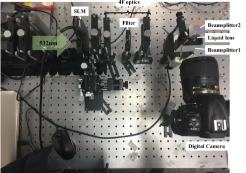
Our proposed optical see-through head mounted display is illustrated in Fig. 1. A SLM (Holoeye, LC-2012) is used and the wavelength of the laser light source is 532nm (SUWTECH, DPGL-2150). Polarizers are used to set a phase-mostly mode of the SLM. 4F optics are used with a spatial filter to eliminate aliasing errors and DC noise. A liquid lens (Optotunes, EL-10-30-TC) is combined with a concave lens to adjust the diopter from 0 D to 20 D. The liquid lens is controlled by a PC. If the liquid lens is set at 0 D, it acts like a transparent screen. Therefore, the hologram can be delivered to the eyes without any distortion. On the other hand, if the liquid lens is set with 20 D, the light is focused in the plane of the entrance pupil, and a maxwellian view is provided. Hence, the observer can see accommodation-free images. Commercially available liquid lenses are Varioptics and Optotunes. The Varioptics electrowetting liquid lens provides less outer size and no gravity problem, but it cannot give large diameter and a fast response. On the other hand, the Optotunes liquid lens can give a large diameter with high speed, but it has problems of small
diopter changing ratio, bulky size, and a gravity problem. Although the gravity problem causes a significant reduction of image quality, operation speed is much more important in our research and we therefore applied an Optotunes liquid lens on the beamsplitter, as shown in Fig. 1. The beam-splitter and the spatial filter are not proper choices for use with head-mounted display optics due to the light paths, sizes and weights of these components. However, due to the small diffraction angle of the SLM, 4f optics with a spatial filter is an inevitable option to reconstruct the hologram [16]. The spatial filter and 4f optics can be removed, if the pixel pitch become sufficiently small. Moreover, the beam-splitter needs to be replaced with thin and lighter optical elements such as holographic film and a half-reflection mirror. In this paper, we focused on verifying the feasibility of an optical see-through head-mounted display that simultaneously expresses both the holographic view and the Maxwellian view using a liquid lens (see Table 1).
Table 1. Specifications of SLM and liquid lens
Spatial Light Modulator (LC-2012) Liquid lens (EL-10-30-TC) Number of pixels 1024x768 Diotper range + 8.3 D ~ + 20 D
Pixel pitch 36 um (58% fill factor) Clear aperture(diameter) 10 mm
Active area 36.9 x 27.6 mm Lens type Plano convex
Frame rate 60 Hz Response time < 2.5 ms
Fig. 1. Our proposed optical see-through head mounted display configuration.
The FOV and the exit pupil are calculated for the holographic view and the Maxwellian view, respectively. In the proposed display, the holographic view is an unmagnified holographic display system [22]; hence, the FOV and the exit pupil can be expressed as follows:
FOV.H 2 arc sin 2 p λ = × (1) FOV Exit Pupil.H d tan
2
= ×
(2)
In these equations, λ, p, and d denote the wavelength, the pixel pitch, and the distance between the hologram and the pupil plane, respectively. The holograms are reconstructed at a distance of 1.5m from the pupil plane. Thus, the FOV and the exit pupil are correspondingly 0.85° and 11.27mm, sufficient to cover the movement of the pupil within 11.27mm x 11.27mm (the pupil moves +/4mm when the eye gazes at +/−25deg). The FOV should be larger to cover pupil movement fully. Generally, diverging light-based holographic projection
can achieve a large FOV. However, it decreases the size of the exit pupil [22], and collimated illumination is necessary to achieve the Maxwellian view in the proposed display [17,18].
On the other hand, the Maxwellian view has a very small exit pupil [17], which is same with airy disk size, as shown in Fig. 5. Thus, the FOV and the exit pupil of the Maxwellian view can be expressed as
FOV.M 2 arc tan r
f = × (3) Exit Pupil.M 1.22 f r λ = (4)
r and f denote radius and focal length, respectively. In our proposed display, r and f are 5mm and 50mm, hence the FOV and the exit pupil is 11.42° and 6.5um. The exit pupil is too small to cover pupil movement. It is a major problem in the Maxwellian view display. To solve such a problem, light source position movement [23] and optical axis tiltable optical elements [24] are suggested as a solution. However, it still needs further study to enlarge the exit pupil and the FOV.
2.2 Layer based synthesis hologram
There are many ways to calculate complex amplitude for a hologram such as a point cloud based hologram [25], polygon based hologram [26], and layer based hologram [27], respectively. Compared with point cloud and polygon based holograms, a layer based synthetic hologram can be implemented easily and quickly without hologram image reduction [27,28]. In addition, an angular spectrum algorithm and a Fresnel diffraction algorithm were suggested as transfer functions for a layer-based hologram. However, due to the paraxial approximation of the Fresnel diffraction, using the Fresnel diffraction algorithm causes calculation errors in systems with a high numerical aperture [29]. Thus, in this paper, the angular spectrum from each layer was synthesized based on the fast Fourier transform. First, the complex 3D scene is divided into a few layers according to depth information, where i = 1, 2… N is the index UN. Each layer is synthesized as a complex amplitude distribution of sub-holograms based on a fast Fourier transform (FFT). In addition, the complex amplitude of the sub-hologram is pointwise multiplied by the angular spectrum transfer function. Then, by adding all complex amplitude distribution of sub-hologram, we can obtain the complex amplitude distribution of the entire hologram, as shown in Fig. 2.
(
)
n 0 u, v, z FFT{ (x, y, )} H (u, v, ) N N N n F n U U z z = =∑
⋅ (5)Where u and v are spatial frequencies. HF is an angular spectrum transfer function and it can be described as
( )
u, v exp [ jkz 1 2 2 2 2]F
H = −λ u −λ v (6)
where k = 2π/λ is the wave number and λ and z are respectively the wavelength and the propagation distance.
Fig. 2. Diagram of layer based synthesis hologram.
To avoid aliasing errors, the hologram should be reconstructed beyond the effective distance. The effective distance is related with the pixel pitch, the SLM width, and wavelength, and it can be expressed as
2 2
z=L 4(Δ )x λ− − 1 (7)
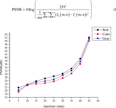
L and Δx denote the SLM width and the pixel pitch, respectively. The pixel pitch and the SLM width of our SLM are 36um and 36.9mm, respectively. Hence, the effective distance is around 5m. However, in our set-up, a liquid lens of 10mm diameter is used, and hence the effective distance is short, 1.35m. However, since the liquid lens serves as a low-pass filter, the smaller the lens diameter results in lower hologram quality, as shown in Fig. 3. The white letters in Fig. 3 indicate the diameter of the liquid lens. The first row shows bolts, the second row represents the gear, and the last row represents the cube. As the diameter of the liquid lens becomes larger, the information of the high-frequency region is added and the hologram is expressed more clearly. No diffusive reflection information is added because when we fill the inside of the hologram with diffusive random phase, the whole hologram looks blurry.
Fig. 3. Numerical calculated hologram by changing the liquid lens diameter (a-d) Bolt, (e-h) Gear, and (i-l) Cube.
We performed numerical calculation of the PSNR between the original hologram and the band limited hologram for each case of liquid lens diameter, as can be seen in Fig. 4. The PSNR is expressed as
(
)
(
)
2 2 0 0 0 255 PSNR 10log 1 ( , , ) m n r I m n I m n mn = − ∑ ∑
(8) 0 5 10 15 20 25 30 35 40 45 50 16 18 20 22 24 26 28 30 32 34 36 38 40 42 44 46 48 50 52 54 PSN R (d B ) Aperture (mm) Bolt Cube GearFig. 4. PSNRs comparison by increasing the liquid lens diameter.
Generally, a higher PSNR indicates higher image quality. In addition, the PSNR typically should be at least 30dB to guarantee image quality [30]. The numerically calculated PSNR is
enhanced by increasing the liquid lens diameter. Unfortunately, the currently used liquid lens is not sufficient to obtain more than 30dB. However, some researchers have developed larger diameter liquid lenses, which can be a solution to overcome the above problems [31–33].
2.3 Maxwellian view
Fig. 5. Simplified schematic of maxwellian view.
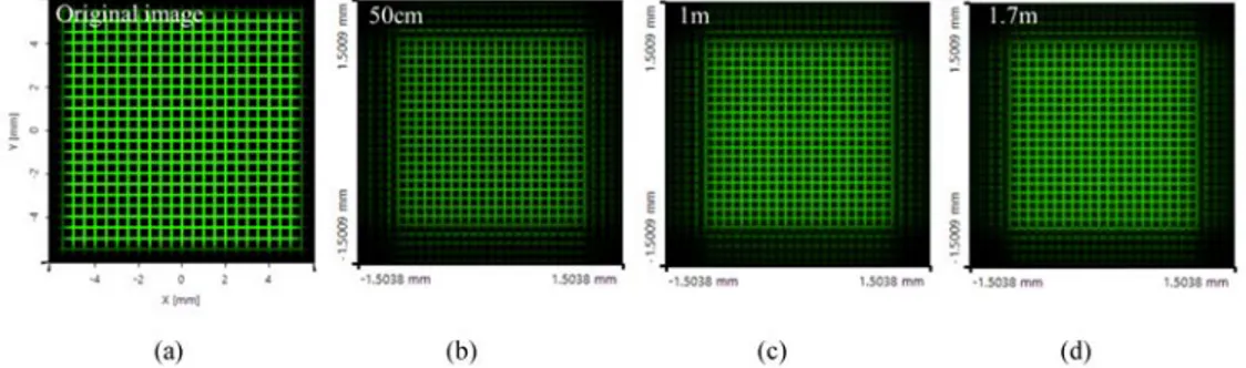
To achieve a maxwellian view, first coherent light should be induced into the phase-mostly mode SLM, and the liquid lens is placed at 1f distance. The light is then focused at the entrance of the pupil, as shown Fig. 5. We can then obtain a maxwellian view. Also, we simulated the field distribution of our proposed maxwellian view optics with VirtualLab (trial version). In the simulation, a grid image has cell size of 500um and line width of 100um. As can be seen in Fig. 6. the field distribution of the grid image is changed little as the diopter of the eye is changing.
Fig. 6. Field distribution of grid image on our proposed maxwellian view optics, when eye focuses on (b) 50cm, (c) 1m, and (d) 1.7m.
3. Optical experiment results of our proposed optical see-through head mounted display
Our SLM is too large to be implemented in a miniaturized optical see-through head mounted display. Thus, we set up the proposed system on an optical table.
Fig. 7. Configuration of our proposed dual view optical see-through head mount display.
First, the liquid lens is set to 0 D before reconstructing the hologram. We use cube and bolt as holograms, as can be seen in Fig. 7. They are reconstructed at 1.5m from the digital camera (NIKON D90). Each object consists of 255 layers. The small yellow box in Fig. 8 is a magnified image of a reconstructed hologram. It is similar to the simulated result. Although the spatial filter in 4F optics removes the aliasing error and DC noise, they still remain near the hologram. Although a narrower spatial filter can remove the noise perfectly, in this case, the maxwellian view becomes too dark to see because the spatial filter cuts the backlight partially. Therefore, the spatial filter is set to an adequate size.
Fig. 8. Reconstructed hologram at 1.5m with (a) cube and (b) bolt.
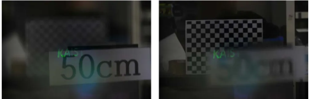
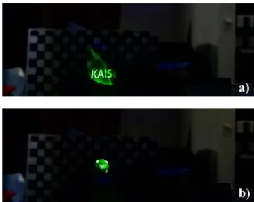
Second, the liquid lens is set to 20 D for the maxwellian view. We applied ‘KAIST’ text as an input image. The digital camera is then manually focused at 50 cm and 1.7 m, as shown in Fig. 9. The ‘KAIST’ letters are always in focus. However, the letter ‘T’ is slightly darker than the other letters because the spatial filter cuts the backlight partially, as mentioned above.
Fig. 9. Maxwellian view of 'KAIST ' letters formed at 50cm and 1.7m position.
Finally, to realize a hologram and a maxwellian view simultaneously, the liquid lens and the SLM were synchronized. Our SLM is driving with 60Hz and a 60Hz GIF format image is produced by placing the hologram and the maxwellian view image at intersections. The image is then put into the SLM and synchronized with the liquid lens, as shown in Fig. 10. A high speed Nikon J5 camera, which can record video at 400fps, is used. Although it has a low resolution of 800x239, it is enough to confirm the time multiplexed images.
Fig. 10. Simplified Time multiplexing system schematic.
We confirm the Maxwellian view and holographic view during the time multiplexing operation, as shown in Fig. 11(a). However, the size of hologram was too small to capture clearly, and it appears vignetted, as shown in Fig. 11(b). This is caused by synchronization problems between the liquid lens and the SLM, as we manually utilized synchronization between two devices in this paper. This can be offset by adding a trigger device. While we do not deal with this issue in the present work, it should be addressed carefully for perfect synchronization.
Fig. 11. (a) Maxwellian view and (b) hologram snapshots during time multiplexing operation.
4. Conclusion
Hologram is a promising technology for 3D displays. In addition, the Maxwellian view based head mount displays have recently been suggested in many studies. Each type of display has advantages to the observer, but they are difficult to combine in a single system. In addition, optical see-through head mounted displays are an appropriate type of display for using the current hologram and the Maxwellian view optics. In this context, two different optics were put into one system using a liquid lens in this research. We also considered the hologram quality according to the liquid lens diameter. Although there was no available large diameter liquid lens, we successfully confirmed the possibility of our proposed optical see-through head mounted display. In addition, the high order diffraction, system size, and hologram resolution can be resolved by using small pixel-sized SLMs or large-diameter liquid lenses. Recently, a LCOS SLM with 3um pixel pitch was commercialized, and we thus expect that it will be possible to implement an optical see-through head mounted display that simultaneously expresses both a hologram and a maxwellian view with superior resolution. We expect that this work can provide a new method for realizing optical see-through head mounted displays.
Funding
Ministry of Science, ICT and Future Planning (GK17D0200).
Acknowledgements
This research was supported by ‘The Cross-Ministry Giga KOREA Project’ of The Ministry of Science, ICT and Future Planning, Korea. [GK17D0200, Development of Super Multi-View (SMV) Display Providing Real-Time Interaction].