Appl. Phys. Lett. 88, 021905 (2006); https://doi.org/10.1063/1.2162672 88, 021905
© 2006 American Institute of Physics.
Holographically generated twisted nematic
liquid crystal gratings
Cite as: Appl. Phys. Lett. 88, 021905 (2006); https://doi.org/10.1063/1.2162672
Submitted: 18 July 2005 . Accepted: 16 November 2005 . Published Online: 10 January 2006 Hyunhee Choi, J. W. Wu, Hye Jeong Chang, and Byoungchoo Park
ARTICLES YOU MAY BE INTERESTED IN
Liquid-crystal diffraction gratings using polarization holography alignment techniques
Journal of Applied Physics 98, 123102 (2005); https://doi.org/10.1063/1.2146075 Highly stable polarization gratings in photocrosslinkable polymer liquid crystals
Journal of Applied Physics 94, 1298 (2003); https://doi.org/10.1063/1.1587269
Three-dimensionally modulated anisotropic structure for diffractive optical elements created by one-step three-beam polarization holographic photoalignment
Holographically generated twisted nematic liquid crystal gratings
Hyunhee Choi and J. W. Wua兲
Department of Physics, Ewha Womans University, Seoul 120-750, Korea Hye Jeong Chang
The Institute of Optics, University of Rochester, Rochester, New York 14627 Byoungchoo Park
Department of Electrophysics, Kwangwoon University, Seoul 139-701, Korea
共Received 18 July 2005; accepted 16 November 2005; published online 10 January 2006兲 A reflection holographic method is introduced to fabricate an electro-optically tunable twisted nematic共TN兲 liquid crystal 共LC兲 grating, forgoing the geometrical drawing. The photoisomerization process occurring on the LC alignment layers of an LC cell in the reflection holographic configuration gives a control over the twist angle, and the grating spacing is determined by the slant angle of reflection holographic configuration. The resulting diffraction grating is in a structure of a reverse TN LC, permitting a polarization-independent diffraction efficiency. The electro-optic tunability of the diffraction efficiency is also demonstrated. © 2006 American Institute of Physics. 关DOI:10.1063/1.2162672兴
Liquid crystals 共LCs兲 are widely employed in optical devices having functions such as beam steering and beam shaping as well as LC diffraction grating. In particular, the ability to control the diffraction efficiency electrically ren-ders an LC grating very important optical component. Previ-ous works to fabricate an LC grating adopt contact treat-ments of the LC alignment layer by a double rubbing technique1,2and a microrubbing employing atomic force mi-croscope tips3or metallic balls.4,5While a noncontact optical treatment of the LC alignment layer has been introduced6 and is also employed in fabricating a LC grating,7the grating is generated directly by a microcontrol of a single writing beam. In both the contact and noncontact treatments, it is necessary to have a high-precision control of positioning in a micron scale, since the fabrication of the LC grating is based on the simple geometrical drawing of one-dimensional lines on the LC alignment layer.
When an azobenzene-containing polymer is employed as an LC alignment layer, the trans-cis photoisomerization pro-cess is known to be an effective means to achieve a surface alignment in an LC cell.6In an LC cell fabricated with pho-toaligned alignment layers, due to the dichroic absorption property, an asymmetric attenuation takes place when two orthogonally linearly polarized beams are counterpropagat-ing inside the LC cell. The polarization interference pattern formed inside the LC cell gives rise to a formation of micro-sized polarization domains, which corresponds to a reflection holographic inscription of interference patterns. In this letter, we employ the reflection holographic method to fabricate a twisted nematic共TN兲 LC diffraction grating.
The photopolymer is commercially available from Sigma-Aldrich, which is an azobenzene side-chain polymer, poly关共methylmethacrylate兲-co-共disperse red 1 methacrylate兲兴共PDR1-MMA兲. PDR1-MMA was dissolved in tetrahydrofurane by 3 – 4 wt. %. A photoalignment layer of 300 nm thick polymer film was readily obtained by spin coating onto indium tin oxide共ITO兲 substrate and subsequent drying for 1 h at 100 ° C. The UV-visible spectrum of the
PDR1-MMA film showed the absorption peak at 490 nm, and the optical density at 514.5 nm, the wavelength of writ-ing beams, was about 0.8. An empty cell, separated by 9.2m spacers, is fabricated by gluing two PDR1-MMA spin-coated ITO substrates with a UV-curable epoxy. Filtered mixtures of a nematic LC 共ZLI-2293, ⌬n=0.1322, Merck兲 and 0.3 wt. % DR1 are introduced into the empty cell by a capillary action at the temperature of 55 ° C. The resulting LC cell at room temperature did not exhibit any optical bi-refringence, since no alignment process has been performed on the surface of the photoalignment layers. As a priming to induce an optical birefringence, a photoalignment of the filled LC cell was carried out by a normal-incident illumina-tion of the 514.5 nm line of an Ar+ laser with the linear polarization along the y axis, called S polarization, the inten-sity of which is 100 mW/ cm2 on the film with a typical illumination time of 30 min 关see Fig. 1共a兲兴. The photoi-somerization process occurring in the azobenzene moiety in-side the two photoalignment layers of PL1 and PL2 resulted in an optical birefringence in the nematic LC cell with the optic axis along the x axis. We note that the birefringent nematic LC cell also exhibits a dichroic absorption, namely, a polarization-dependent absorption, at a wavelength of 514.5 nm.
Now we examine what kind of the polarization modula-tion results when two counterpropagating beams interfere. In the S / P-polarization reflection hologram, the polarization modulation is given as
Es
+ + Ep
−
= Eoscos共t − kz +兲yˆ + Eopcos共t + kz兲xˆ
⬇ Eop兵cos kz cost关Eos/Eopyˆ + xˆ兴
+ sin kz sint关Eos/Eopyˆ − xˆ兴其, 共1兲
where Es+and Ep−denote S- and P-polarization electric fields
propagating along the +z and −z axes, respectively, and is the phase difference between the two. When Eos= Eop, Eq.
共1兲 describes two standing waves with wave planes of 共xˆ + yˆ兲/
冑
2 + zˆ and共−xˆ+yˆ兲/冑
2 + zˆ, and a polarization modulation results from the optical interference, as shown in the middle row of Fig. 1共b兲. We find that the polarization state goesa兲Electronic mail: [email protected]
APPLIED PHYSICS LETTERS 88, 021905共2006兲
through a periodic modulation from right-circular to linear to left-circular to linear polarizations along the z axis, which corresponds to the sample depth direction. However, when Eos⫽Eop, the wave planes of two standing waves deviate
from the planes of 共xˆ+yˆ兲/
冑
2 + zˆ and 共−xˆ+yˆ兲/冑
2 + zˆ, and at the same time a polarization modulation from right-elliptical to linear to left-elliptical to linear polarizations is produced along the z axis, as described in the top and bottom rows 共Eos⬎Eop or Eos⬍Eop兲 of Fig. 1共b兲. When the birefringentnematic LC cell is positioned inside the polarization modu-lation produced, S-polarized light 共polarization along the y axis兲 goes through an optical attenuation less than P-polarized light共polarization along the x axis兲 does, owing to the dichroic absorption of the LC cell. When counter-propagating through the dichroically absorptive LC cell, two S- and P-polarized lights with initial equal intensities, Eos共1兲 = Eop共2兲, get attenuated by a different amount, resulting in Eos共1兲⬎Eop共1兲on PL1 layer and Eos共2兲⬍Eop共2兲on PL2 layer, which was made possible by the presence of low-level 0.3 wt. % doping of DR1 in the LC. The resulting polarization phase modulation inscribed on PL1 and PL2 layers will be the top and bottom ones shown in Fig. 1共b兲, respectively.
In order to inscribe the polarization grating inside the birefringent nematic LC cell, two counterpropagating beams with orthogonal S and P linear polarizations from the 514.5 nm line of an Ar+laser are prepared as writing beams by use of a beam splitter and half-wave plates. The light intensity was 200– 300 mW/ cm2 and the illumination time was 10– 20 s. In the case of a normal incidences= 0, the
polarization state, corresponding to one of the polarization states described in the top or bottom rows of Fig. 1共b兲, is uniform on the entire x-y plane of PL1 and PL2 layers, which is the photoalignment polymeric surface. However, when the birefringent nematic LC cell is slightly slanted with a slant grating angle s of 0.1°–2.0° in a reflection
holo-graphic configuration, as shown in Fig. 1共a兲, a periodic modulation of polarization state emerges along the x axis on the photoalignment polymeric surface with the period ⌳
=/4 sins, determined by the slant grating anglesand the
wavelength of writing beam , as shown magnified inside the circle of Fig. 1共a兲. In the current experimental configu-ration, Eos⬎Eop on the PL1 layer, Eos⬍Eop on the PL2
layer, ands⫽0; hence, the major axes of the two modulated
elliptical polarizations on the PL1 and PL2 layers do not coincide. Now, on each PL1 and PL2 layer the presence of a modulated polarization state gives rise to a modulated orien-tation of azo moieties along x axis on the surface of the LC alignment layer via photoisomerization process, and the rela-tive orientational direction of azo moieties inside two facing alignment layers PL1 and PL2 are determined by the values of the ratio Eos/ Eopat each layer. A nonparallel orientation of
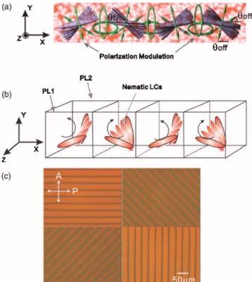
azo moieties inside two photoalignments gives rise to a TN structure inside the birefringent LC cell, twisted in x-y plane with the twist axis along the z axis. Furthermore, at the sur-face of each alignment layer, the alignment of LCs is achieved by an orthogonal photoalignment following the zigzag-shaped polarization modulation pattern along the x axis with a nonzero offset angle off with respect to the x axis, and the offset angles are different in PL1 and PL2关see Fig. 2共a兲兴. This leads to a formation of two different kinds of TN domains: one twisted in the clockwise sense and the other twisted in the counterclockwise sense. The resulting LC grating is in the structure of a reverse TN LC grating2 关see Fig. 2共b兲兴.
From the measurement of the dichroic absorption of the fabricated birefringent cell, the ratios Eos/ Eop at PL1 and PL2 are determined as 3.0 and 1.0, respectively. From the relation of the offset angle off with the ratio Eos/ Eop, i.e.,
tan共off兲=Eos/ Eop, we find that the axes of the linear
polar-FIG. 1.共Color online兲 共a兲 Reflection holographic configuration to inscribe the S- and P-polarization modulation in a nematic LC cell with the inset showing a magnified view of the polarization modulation formed on the surface of the azo photoalignment layer.共PL1 and PL2: azo photoalignment layers 1 and 2,s: the slant grating angle兲. 共b兲 The polarization modulation
from the interference of S- and P-polarized writing beams for three different intensity ratios.
FIG. 2.共Color online兲 Schematic illustration of the LC grating formed by the polarization modulation and microtextures.共a兲 The front view 共t: the
twist angle of TN domain,off: the offset angle of the polarization direction
with respect to x axis兲. 共b兲 A reverse twisted nematic LC cell. 共c兲 The microscopic texture of TN domains taken with an optical polarizing micro-scope共upper left:= 0°, upper right:= −45°, lower left:= + 45°, lower right:= 90°兲.
ization state appearing in the polarization modulation are ro-tated by +75° at the PL1 layer and +35° at the PL2 layer relative to the +x axis.
The reverse TN LC grating structure is examined by observing the textures of the LC cell in a polarizing optical microscope. The light path is from the polarizer to PL1 to PL2 to the analyzer, with the polarization axis of the polar-izer along the y axis. As seen in Fig. 2共c兲, the microscopic textures, characteristic of a phase grating, confirm the pres-ence of a TN array. The upper left, the upper right, the lower left, and the lower right ones correspond to the textures for the sample rotation angles of= 0°, −45°, +45°, and 90° of the grating vector relative to the polarization axis 共x axis fixed in the laboratory兲 of the polarizer, respectively. We de-termine that the offset angles are⬃20° and ⬃60° at the PL1 and PL2 layers, respectively, which gives the twist anglet
= 40°. We found thattdepends on the LC cell thickness and
that it can be increased up to 90° for a thick cell.
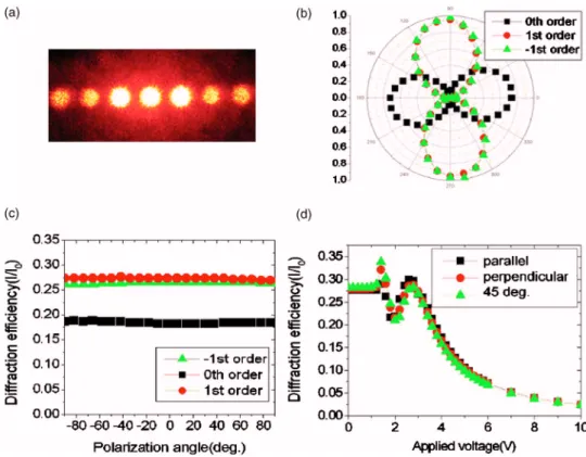
Next, the diffraction property of the fabricated LC grat-ing is investigated with the 632.8 nm line of a less than 1 mW He–Ne laser. In Fig. 3共a兲 is shown a CCD picture of the diffraction pattern. The polarization state of the outcom-ing diffracted order is examined and is plotted in Fig. 3共b兲. The polarization direction of the light propagating from PL1 to PL2 is y polarized, perpendicular to the grating vector, with the angle 0° corresponding to the y axis. The ±1 orders go through a 90° rotation in the polarization state, while there is no change for the 0th order.8Figure 3共c兲 shows the polarization independence of the diffraction efficiencyfor the 0th and ±1st orders, which is the characteristic feature of a reverse TN LC grating. We then looked into the electro-optic tunability of the diffraction efficiency by measuring the diffraction efficiency of the −1st order as a function of the
applied voltage. As shown in Fig. 3共d兲, below the Freeder-icksz transition, is constant and polarization independent, while there appear different changes in depending on the polarization when undergoing the Freedericksz transi-tion. Above ⬃3 V beyond the Freedericksz transition, is again polarization independent and exhibits a smooth electrotunability.
In summary, a liquid crystal grating is fabricated in a slanted reflection holographic configuration by inscribing an S- and P-polarization interference via a photoisomerization process. The resulting grating is in a structure of a reverse twisted nematic LC, which permits the polarization-independent diffraction efficiency. The electro-optic tunabil-ity of the diffraction efficiency is also demonstrated. The novel LC grating proposed here should find a wide application in optical devices employing LCs as electro-optic materials.
This work is supported by ABRL program at Ewha Womans University as well as by Korea Research Foundations共Grant No. 2004-C00057兲.
1J. Chen, P. J. Bos, H. Vithana, and D. L. Johnson, Appl. Phys. Lett. 67,
2558共1995兲.
2C. M. Titus and P. J. Bos, Appl. Phys. Lett. 71, 2239共1997兲.
3J.-H. Kim, M. Yoneya, and H. Yokoyama, Nature共London兲 420, 159
共2002兲.
4M. Honma and T. Nose, Jpn. J. Appl. Phys., Part 2 42, 6992共2003兲. 5S. Varghese, G. P. Crawford, C. W. M. Bastiaansen, D. K. G. de Boer, and
D. J. Broer, Appl. Phys. Lett. 85, 230共2004兲.
6P. J. Shannon, W. M. Gibbons, and S. T. Sun, Nature共London兲 368, 532
共1994兲.
7W. M. Gibbons and S.-T. Sun, Appl. Phys. Lett. 65, 2542共1994兲. 8Z. He and S. Sato, Appl. Opt. 37, 6755共1998兲.
FIG. 3.共Color online兲 共a兲 A CCD pic-ture of diffraction orders,共b兲 the polar plot of the polarization state of dif-fracted orders,共c兲 the diffraction effi-ciency as a function of the polarization angle, and 共d兲 the diffraction effi-ciency as a function of the applied voltage.