Thermal Hydraulic Analysis of the MEGAPIE Target under Beam Wandering
Chungho Cho, Nam-il Tak, and Tae Yung SongKorea Atomic Energy Research Institute, 150 Deokjin-dong, Yuseoung-gu, Daejeon, 305-353, South Korea [email protected]
1. Introduction
For many decades, efforts have been made to reduce the amount of nuclear wastes. To incinerate the long-lived radioactive nuclides, an accelerator driven system (ADS) is considered to be one of the most favorable solutions [1].
In an ADS, a high energy proton beam is impinged on a heavy metal target to produce spallation neutrons which are multiplied in a sub-critical blanket. Therefore, the spallation target is one of the most important units in an ADS. One of the key issues in the target design is how to design an appropriate beam window and a LBE flow so that the system can sustain thermal and mechanical loads as well as radiation damage.
In Europe, intensive research and development programs are now underway relating to the ADS technology. To gather practical experience relating to liquid metal targets, the pilot target MEGAPIE (MEGAwatt Pilot Experiment) has been designed and fabricated in Europe [2]. The KAERI is actively involved in this project, especially in the thermal-hydraulic design of the target.
The present work is dealing with the thermal hydraulic analysis of the MEGAPIE target with a beam wondering. A series of numerical simulations to consider the consequences of beam wonderings away from the target axis have been performed using a computational fluid dynamics (CFD) code. The results achieved are presented and discussed.
2. Numerical Approach
Figure 1 shows the computational domain of the MEGAPIE target schematically [3]. Liquid lead-bismuth eutectic (LBE) is used as target material and as coolant to remove the heat released in the target. The LBE is circulated with electromagnetic pumps downward through the annular gap between both cylinders. It makes a U-turn at the bottom and flows upwards through the inner cylinder, called guide tube. The LBE flow rates of the main and bypass are 37.5kg/s and 2.5kg/s, respectively. The proton beam current is 1.74mA and the LBE inlet temperature is 230°C.
The present CFD analysis is made using the CFX 4.4 code [4]. In the present analysis, all the cases use the standard k-ε turbulence model to predict the turbulent flow characteristics, and the logarithmic law-of-the-wall to predict the near- the-law-of-the-wall characteristics.
Figure 1. The computational domain of the MEGAPIE target (unit: mm).
Six cases are envisaged, for an assumed beam offset of 2mm along and perpendicular to the bypass flow, and at 45° to it, as shown in Figure 2. Case 1 is the normal operating conditions.
Figure 2. Matrix of beam offset cases considered.
3. CFD Results
Figure 3 shows the temperature distribution in the target under the normal operating conditions (Case 1).
Transactions of the Korean Nuclear Society Autumn Meeting Busan, Korea, October 27-28, 2005
Table 1 shows the major calculated peak temperatures for all the cases.
(a) X-Z Plane (b) Y-Z Plane
Figure 3. Temperature distributions in the target under the normal operating conditions (Case 1).
The results of the calculations show that the maximum window temperature in all cases is kept below the design value of 400℃.
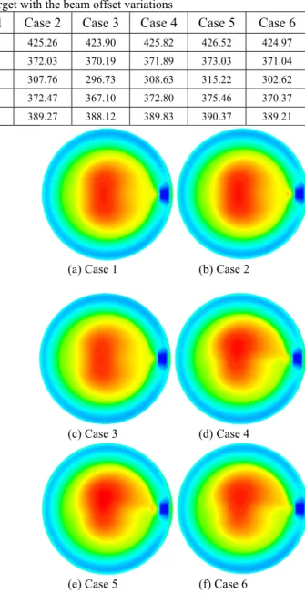
Figure 4 shows the temperature distribution at the z=0.15m in all the cases. It shows that the hot temperature region is shifted according to the change of the location of the beam center.
4. Conclusions
The present results confirm the stability of the cooling arrangement, the robustness of the lower target configuration, and the relative insensitivity to parametric variations. The maximum temperatures over the window are varied by ±2°C only, by up to 13°C elsewhere on the hull, and by 15°C within the LBE itself.
Acknowledgement
The Korean Ministry of Science and Technology supported this study. This work was performed under the MEGAPIE cooperation. The authors acknowledge that Mr. T.V. Dury in PSI provided the major inputs for the CFX analysis.
(a) Case 1 (b) Case 2
(c) Case 3 (d) Case 4
(e) Case 5 (f) Case 6
Figure 4. Temperature distributions at the z=0.15m.
REFERENCES
[1] C. Rubbia, Accelerator-Driven Sub-Critical Systems for Radioactive Waste Transmutation and Energy Production, Karlsruhe Talk, Oct. 2000.
[2] M. Salvatores, G. Bauer, G. Heusener, The MEGAPIE Initiative – Executive Outline and Status as per November 1999, Paul Scherrer Institut, 1999. [3] G. Bauer, et al., Description of SINQ and Boundary Conditions for MEGAPIE, 1st MEGAPIE General
Meeting, CEA, Cadarache, 14.-15., June 2000. [4] CFX 5.7 Manuals, ANSYS Incorporated, 2004.
Table 1. Peak temperatures in the target with the beam offset variations
Case No. Case 1 Case 2 Case 3 Case 4 Case 5 Case 6
Max. LBE temperature (℃) 424.64 425.26 423.90 425.82 426.52 424.97
Max. window temperature (℃) 371.00 372.03 370.19 371.89 373.03 371.04
Max. hull temperature (℃) 301.99 307.76 296.73 308.63 315.22 302.62
Max. guide tube temperature (℃) 369.64 372.47 367.10 372.80 375.46 370.37
![Figure 1 shows the computational domain of the MEGAPIE target schematically [3]. Liquid lead-bismuth eutectic (LBE) is used as target material and as coolant to remove the heat released in the target](https://thumb-ap.123doks.com/thumbv2/123dokinfo/4970037.52806/1.892.503.770.237.621/computational-megapie-schematically-bismuth-eutectic-material-coolant-released.webp)