INTRODUCTION
Soft magnetic thin film materials have been applied to various magnetoelectronic devices such as magnetic ran-dom access memory(Iwata-Harms et al. 2018; Zhang et al. 2018), data storage device(Maat et al. 2016), spin logic based devices(Fuji et al. 2018; Oh et al. 2019), etc. The magnetic thin film material is generally manufactured by sputtering system and its physical properties are determined by process conditions such as gas atmosphere and input power and composition of the target. Many materials hav-ing compositions such as CoFeB, FeTaN, CoNbZr and Fe-AlO have been studied(Fergen et al. 2002), and are used in a single layer or multi-layers to form a circuit together with an insulating film and an electrode(Baek et al. 2018; Correa et al. 2019). Soft magnetic thin films applied to electronic devices require high saturation magnetization, low coerciv-ity, and high permeability. The saturation magnetization is determined by the composition of the ferromagnetic
materi-als and the coercivity is known to depend on the grain size (Alben et al. 1978; Lavrijsen et al. 2011). In order to induce a high permeability, it is necessary to control magnetic an-isotropy, which includes crystal magnetic anan-isotropy, shape magnetic anisotropy, and induced magnetic anisotropy.
Although the deposition method using sputtering is ex-cellent in terms of productivity, it is limited in grain control because it is deposited in a cluster form. Radiation technol-ogies are used in modification of thin film technoltechnol-ogies(Oh et al. 2019). Ion implantation is used to strengthen the me-chanical properties(Shanaghi et al. 2019) and control the doping concentration of semiconductors while maintaining the main properties of the material(Chen et al. 2018; Wong et al. 2019). The purpose of studying the application of ion implantation process to magnetic thin film materials is to improve the partial characteristics such as coercivity and permeability while maintaining the main characteristics such as saturation magnetization. If the physical properties of the magnetic thin film is improved through such modifi-cation, it is considered that the loss of the electronic device can be reduced and further contribute to the improvement of the physical properties through the improvement of the
Ion Implantation Effects on CoFeB Magnetic Thin Films
Hyun Bin Kim1,2, Seung Hwan Oh1, Byong-Guk Park2, Hoje Kwon1 and Jin Mun Yun1,* 1Korea Atomic Energy Research Institute Jeongeup-si, Jeollabuk-do 56212, Republic of Korea 2Department of Materials Science and Engineering, KAIST, Daejeon 34141, Republic of Korea
Abstract - Magnetic thin film materials are used in various electronic device fields. We simulated the change of physical properties of magnetic thin film material by ion implantation and conducted experimental verification. From the simulation results, it was possible to predict the etching by ion beam, which showed a decrease in the saturation magnetization. In addition, the simulation results confirmed that atomic diffusion may occur at the interface between the magnetic thin film material and the substrate, and vacancies may occur inside the thin film material. This was shown to decrease the coercivity due to the decrease of the grain size of the magnetic thin film. As a result, the decrease in saturation magnetization was minimal due to the ion implantation, but the coercivity was reduced by more than 2 times, which may contribute to the development of low power electronic devices.
Key words : Ion implantation, Magnetic thin film, Simulation
─ 357 ─ Technical Paper
* Corresponding author: Jin Mun Yun, Tel. +82-63-570-3055, Fax. +82-63-570-3068, E-mail. [email protected]
resonance frequency. Therefore, this study simulates the physical changes that occur when nitrogen ion implantation into CoFeB magnetic thin film material and analyzes the ef-fect on magnetic properties.
EXPERIMENTAL PROCEDURE
1. Thin film deposition
Magnetic thin films with thickness of 20 nm were depos-ited on to a oxidized silicon wafer substrate(1.25×1.25cm) using a DC magnetron sputtering system. Deposition condi-tion was Ar atmosphere of 2mTorr at a input power of 100 W and background pressure was less than 5×10⁻⁷ Torr. The composition of target was Co32Fe48B20(at%). The thick-ness of the thin films was controlled by deposition time and measured by an alpha step.
2. Ion implantation and simulation
Nitrogen ion implantation was carried out on magnet-ic thin film deposited wafer using ion implanter in Korea Atomic Energy Research Institute(KAERI). The fluence was varying from 1014 to 1016 ions·cm-2 with 20keV accel-eration voltage.
The effects of ion implantation were simulated using “The Stopping and Range of Ions in Matter”(SRIM) code(Ziegler et al. 2010). Simulation conditions were set with sample structure, top layer Co32Fe48B20(at%) with 20nm, middle layer SiO2 with 100nm and bottom layer Si. Density of top and middle layer was automatically calculated, 7.09g·cm-3 and 1.72g·cm-3 . The effects was calculated with 99,999 ions on only in 30nm thickness with TRIM calculation, “Damage calculation with full Damage Cascades option”.
3. Magnetic properties
The magnetic properties were measured using a vibrat-ing sample magnetometer with an applied magnetic fields, varying from -100 to 100 Oe parallel to the film plane. The saturation magnetization was calculated by magneti-zation(emu) values at maximum applied field dividing the sample volumes and coercivity was obtained at the inver-sion points of magnetization. These samples have uniaxial anisotropy characteristic in plane, easy and hard axis.
RESULTS AND DISCUSSION
1. Ion distribution
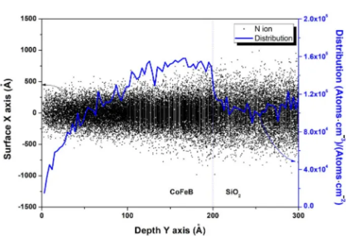
The simulation was conducted by simulating the condi-tions as the ion implantation of the prepared specimen. The nitrogen ions distribution inside the specimen is shown in Fig. 1. Ion implantation proceeded in the depth direction from the 0 position of the surface. The gray dots in the fig-ure correspond to the last positions of the ions. As it enters from the magnetic layer surface, the concentration of ions increases to saturate around 10nm and have a constant dis-tribution up to 20nm as an interface. It is thought that scat-tering at the interface is such that the concentration of ions in the interface layer drops sharply. Although not shown in this figure, the average penetration depth of ions is 42.7nm and can reach up to 138nm. Thus, most of the ions are dis-tributed in the CoFeB and SiO2 layers and hardly reach the Si substrate.
2. Recoil atom distribution
The ion implantation causes the movement of target at-oms. Recoil atoms can move into voids that can penetrate the surroundings and form vacancies, or replacement can occur by exchanging positions with surrounding atoms. This phenomenon contributes to the diffusion of atoms as shown in Fig. 2. In the simulation results, it was observed that each atom of the magnetic layer diffused into the SiO2 layer over the interface. The penetration depth reaches ap-proximately 2nm and decreases exponentially. Conversely, atoms in the SiO2 layer also diffuse toward the magnetic layer. This diffusion is considered to be due to the driving
Fig. 1. Ion distribution as a function of the depth in CoFeB/SiO2
layer.
·
·
-force of the scattered ions in the SiO2 layer. Therefore, the diffusion distance in the reverse direction is about 1nm, about half that of the forward direction. At the interface, materials of complex composition will be produced by bidi-rectional diffusion. An oxide may be formed by diffusion of Co and Fe ions in the SiO2 layer, and an amorphous oxide will increase around the CoFe phase in magnetic layer.
The distribution of recoil atoms in each layer shows a similar tendency to the distribution of nitrogen ions in Fig. 1. Since the power of nitrogen ions distribution is 5 in Fig. 1 and recoil atoms are 7, it can be seen that collisions with hundreds of atoms occur before the nitrogen ion stop. These results indicate that the main factor contributing to the change in physical properties of the thin film is due to the atomic diffusion rather than the effect of ion distribution.
3. Vacancy distribution
Fig. 3 shows the vacancy concentration for each element over depth. The distribution of vacancy shows similar re-sults as the distribution of ions and the rere-sults of recoil atoms. The sum of vacancies and replacement collision is 188/ion(which is not shown in figure, identified in simu-lation monitoring program). Unfortunately, the simusimu-lation results do not confirm the type of vacancy such as Schottky and Fenkel defect or the formation of dislocations. It is as-sumed that only a number of defect concentration increases can affect grain size. As will be explained in the next sec-tion, grain size is related to the coercivity of the magnetic properties of the thin film.
4. Magnetic properties
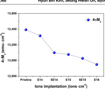
The saturation magnetization of thin film decreases with increasing ion implantation. This is considered as a result by the surface etching of a thin film. In the simulation, the etching rate of each element of the magnetic thin film is Co: 0.43, Fe: 0.65 and B: 0.12 atoms·ion-1. Considering that the composition of the magnetic thin film, the etching rate of Co and Fe depends on the composition. However, B has a lower etching rate than the other two elements. As a result, the composition of B may be relatively increased on the surface. This change in composition is a very small dif-ference that is not enough to affect the magnetic properties. Removal of CoFe from the surface leads to lower saturation magnetization as shown in Fig. 4. Numerically, the mag-netization value 13,400emu·cm-3 of the pristine sample is reduced by 3.4% to 12,950emu·cm-3 by 1016 ion·cm-2 ion implantation. This is expected to cause a thickness re-duction approximately 0.67nm, but this is not a measurable value at the level of several atom layers. Nevertheless, one of the important information from the simulation results is that it can explain the decrease in saturation magnetization and create uneven surface composition changes between CoFe and B.
Fig. 5 shows the coercivity obtained from the magnetic hysteresis curve according to the ion implantation. The co-ercivitiy decreased by ion implantation up to 1015 ion·cm-2, which is thought to be the result of the increase in vacancies described above. The effect of grain size on the coercivity of the magnetic thin film is explained by the random anisot-ropy model(Alben et al. 1978). In the proposed model, the
Fig. 2. Ion and recoil atom distribution as a function of the depth
of CoFeB/SiO2 layer.
-·
·
Fig. 3. Vacancy distribution of CoFeB/SiO2 layers as a function of
coercivity decreases when the grain size is smaller than the magnetic exchange length. An increase in defects caused by ion beam irradiation causes an increase in dislocations, thereby reducing grain size, which may explain the de-crease in coercivity. The inde-crease in coercivity is believed to be due to an increase in compositional heterogeneity. As described above, the composition change is a result of the complex effect of the difference between the composi-tion of CoFe phase and B on the surface, the composicomposi-tion change at the interface due to diffusion, and the change of the composition and the movement of recoil atoms in the entire region of the thin film.
The reduction of coercivity is important for the industrial application of the materials. In the power conversion
func-tion in which a soft magnetic material is used, the power loss can be reduced by reducing the area of the magnetic hysteresis curve corresponding to the magnetic loss. It also has a great advantage in the implementation of network de-vices and equipment using ferromagnetic resonance.
CONCLUSION
The physical properties of CoFeB thin films with soft magnetic properties by ion implantation were simulated and the magnetic properties were studied. Simulation using SRIM code was able to estimate the atom diffusion and va-cancy distribution in the magnetic thin film. It was found that the etching effect predicted in the simulation could cause a decrease in the saturation magnetization. In addi-tion, the expectation that the grain size would change due to the generation of dislocation caused by the increase of the vacancy appeared to be the change of the characteristics of the coercivity. The reduction of magnetic loss by ion im-plantation is expected to lead to the expansion of industrial applications through the improvement of soft magnetic thin film properties.
ACKNOWLEDGMENT
This work was supported by Radiation Technology R&D program through the National Research Foundation of Korea funded by the Ministry of Science and ICT (NRF-2017M2A2A6A01019702). It also technically supported by a Radiation Equipment Fabrication Center in KAERI.
REFERENCES
Alben R and Becker JJ. 1978. Random anisotropy in amor-phous ferromagnets. J. Appl. Phys. 49(3):1653-1658. Baek SH, Amin VP, Oh YW, Go G, Lee SJ, Lee GH, Kim KJ,
Stiles MD, Park BG and Lee KJ. 2018. Spin currents and spin-orbit torques in ferromagnetic trilayers. Nature Mat.
17:509-513.
Chen WQ, Wang XY, Xiao XZ, Qu SL, Jia YZ, Cui W, Cao XZ, Xu B and Liu W. 2018. Characterization of dose de-pendent mechanical properties in helium implanted tung-sten. J. Nucl. Mat. 509:260-266.
Correa MA, Santos JGS, Silva BG, Raza SA, Della Pace RD,
Fig. 5. Magnetic coercivity of CoFeB thin film as a function of the
ion implantation.
·
-Fig. 4. Saturation magnetization of CoFeB thin films as a function
of ions implantation.
·
Chesman C, Sommer RI and Bohm F. 2019. Exploring the magnetization dynamics, damping and anisotropy in engi-neered CoFeB/(Ag, Pt) multilayer films grown onto amor-phous substrate. J. Mag. Mag. Mat. 485:75-81.
Fergen Im Seemann K, Weth AVD and Schüppen A. 2002. Soft ferromagnetic thin films for high frequency applications. J. Mag. Mag. Mat. 242-245:146-151.
Fuji Y, Kaji S, Hara M, Higashi Y, Hori A, Okamoto K, Na-gata T, Baba S, Yuzawa A, Otsu K, Masunishi K, Ono T and Fukuzawa H. 2018. Highly sensitive spintronic strain-gauge sensor based on a MgO magnetic tunnel junction with an amorphous CoFeB sensing layer. App. Phys. Lett.
112(6):062405.
Iwata-Harms JM, Jan G, Liu H, Serrano-Guisan S, Zhu J, Thom-as L, Tong RY, Sundar V and Wang PK. 2018. High-tem-perature thermal stability driven by magnetization dilution in CoFeB free layers for spin-transfer-torque magnetic random access memory. Sci. Rep. 8:14409.
Lavrijsen R. Paluskar PV, Loermans CTJ, van Kruisbergen PA, Kohlhepp JT, Swagten HJM, Koopmans B and Snoeck E. 2011. Magnetism in Co80-xFexB20: Effect of crystallization.
J. Appl. Phys. 109:093905.
Maat S and Marley AC. 2016. Physics and Design of Hard Disk Drive Magnetic Recording Read Heads. Handbook of Spin-tronics. 977-1028.
Oh SH, Kim HB and Yun JM. 2019. Electron Beam-Assisted
Conjugated Polyelectrolyte/Graphene Oxide Hybrid as a Hole Transporting Material in Organic Solar Cells. J. Rad. Ind. 13(3):191-198.
Oh YW, Park KW and Park BG. 2019. Underlayer dependence of electric field effect on magnetic anisotropy and its vol-atility in CoFeB/MgO structures. Curr. Appl. Phys. 19:50-54.
Shanaghi A and Chu PK. 2019. Enhancement of mechanical properties and corrosion resistance of NiTi alloy by car-bon plasma immersion ion implantation. Surf. Coat. Tech.
365:52-57.
Wong MH, Goto K, Murakami H, Kumagai Y and Higashiwa-ki M. 2019. Current Aperture Vertical β-Ga2O3 MOSFETs
Fabricated by N- and Si-Ion Implantation Doping. IEEE Elec. Dev. Lett. 40(3):431-434.
Zhang Y, Yuan HY, Wang XS and Wang XR. 2018. Breaking the current density threshold in spin-orbit-torque magnetic random access memory. Phys. Rev. B 97(14):144416. Ziegler JF, Ziegler MD and Biersack JP. 2010. SRIM-The
stopping and range of ions in matter(2010). Nuc. Instr. Meth. Phys. Res. B 268:1818-1823.
Received: 24 September 2019 Revised: 13 October 2019 Revision accepted: 4 November 2019