153
-Abstract - Voltage Source Converter HVDC (VSC-HVDC) are a better alternative than conventional thyristor based HVDC systems. Unfortunately, VSC-HVDC’s full potential cannot be utilized up till now due to absence of suitable HVDC protection. Recently, hybrid HVDC circuit breakers (HDCCB) have been developed and successfully lab tested. However, their application and feasibility in VSC-HVDC needs to be investigated. In this research paper we have modelled an existing HDCCB and evaluated its impact on fault reduction and interruption in VSC-HVDC systems. The HDCCB was applied in Korean Jeju-Haenam VSC-HVDC system model and its impact was analyzed for HVDC line-to-ground and line-to-line faults. HDCCB successfully interrupted the fault current and prevented the damages to costly IGBTs and converter transformers.
1. INTRODUCTION
Voltage Source Converter HVDC's (VSC-HVDC) full potential cannot be utilized uptill now due to absence of suitable HVDC protection. After a DC fault in VSC-HVDC, the IGBT antiparallel diodes continue to supply DC fault current despite IGBTs being turned off. This is due to the arrangement of IGBT antiparallel diodes in uncontrolled rectifier arrangement. HVDC Circuit Breakers (DCCB) are needed to interrupt the DC fault current [1].
In this research paper we have modelled an existing hybrid type DCCB (HDCCB) and evaluated its impact on fault reduction and interruption in VSC-HVDC systems. An existing topology of HDCCB was modelled. This HDCCB was applied in Korean Jeju-Haenam VSC-HVDC power system model and its impact was analyzed for HVDC cable line-to-ground and line-to-line faults. HDCCB model successfully interrupted the fault current and prevented current to rise to damaging levels which can destroy converter station IGBTs.
2. MAIN BODY 2.1 Hybrid HVDC Circuit Breaker (HDCCB)
AC circuit breakers interrupt AC fault current at its natural zero crossing, but there is no zero point in DC fault current. Forcing the huge and rising DC fault current to zero in HVDC require methods
which are different from AC circuit breakers. One of the methods is inverse voltage generating method in which DCCB reduces the DC current to zero by making the reverse voltage across DCCB higher than the source voltage [2]. HDCCB shown in Figure 1, which works on inverse voltage generation method, was modelled for the presented work and it was proposed in reference [3].
2.2 JEJU HAENAM VSC-HVDC SYSTEM
To meet the power demands of Jeju-island, a 100 km LCC-HVDC submarine cable link exists between Haenam-mainland and Jeju-island [4]. In this research paper we have assumed that the LCC-HVDC of the Jeju-Haenam link was replaced by a VSC-HVDC system [5]. Figure 2 shows the Matlab/Simulink model of the VSC-HVDC connected with the Jeju-island microgrid. The VSC-HVDC contains two-level VSC converters arranged in symmetrical monopole configuration. VSC-HVDC voltage = ±180 kV, Load Current = 800 A, and Power Flow = 300 MW. The rectifier converter is located at Haenam-mainland and inverter converter is located at Jeju-island. Each HVDC transmission line is protected by HDCCBs located at rectifier and inverter converters.
2.3 FAULT SIMULATION ANALYSIS
The objective of fault simulation analysis was to analyse the effect of HVDC faults on the VSC-HVDC system and the source AC system in the absence and presence of HDCCB. HVDC cable line-to-ground and line-to-line faults were made at points marked as Fault 1 and Fault 2 in Figure 2.
전압형 HVDC 시스템 적용을 고려한 Hybrid Type HVDC 차단기의 동작 특성 분석
움아르 아미르 칸, 이종건, 임성우, 이호윤, 이방욱†
한양대학교
Performance Analysis of Hybrid Type HVDC Circuit Breakers in Voltage Source Converter based
HVDC System
Umer Amir Khan, Jong-Gun Lee, Sung-Woo Lim, Ho-Yun Lee, Bang-Wook Lee†
Hanyang University Fault 1 Fault 2 P = 300 MW P = 20 MW P = 180 MW P = 500 MW Q=20 VAR VSC HVDC SYSTEM
<Figure 2> Jeju-haenam VSC-HVDC link modelled in Matlab/Simulink/Simpowersystems.
I2
a b
Surge Arrester Bank I1 Ultrafast Disconnector Switch (UDS) Line Commutation Switch (LCS) Main DC Breaker (MCB) Residual Current Breaker (RCB) IT Current Limiting Reactor
<Figure 1> Single line diagram of HDCCB.
154
2.3.1 DC Line to Ground Fault (Fault 1)
A line-to-ground fault was generated in HVDC cable at a distance of 50 km from the converter stations as shown in Figure 2 and marked as Fault 1. Figure 3 shows the currents measured at the critical points in the system with and without HDCCB present in VSC-HVDC. Figure 3 (a) shows the output current of the rectifier. In the absence of HDCCB, severe first peak fault current flows through the positive line as shown by the dotted line. After application of HDCCB, shown by dark lines, the faulted pole was isolated within three milliseconds.
Figure 3 (b) shows the input DC current at the inverter. In the absence of HDCCB, a huge reverse peak of fault current flowed through the positive line as shown in dotted line. This peak fault current was supplied by the Jeju-island AC grid. After application of HDCCB, as shown by dark lines, the faulted pole was isolated within three milliseconds. Figure 3 (c) shows the single phase current of Haenam-mainland AC grid measured at the output of the rectifier transformer. The HDCCB significantly suppressed the peak of the fault current and protected the transformer and IGBT antiparallel diodes from the unwanted large transient current.
2.3.2 DC Line to Line Fault (Fault 2)
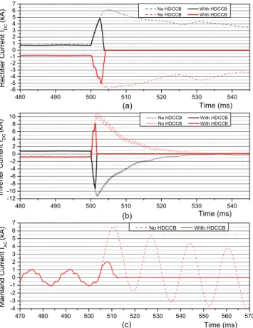
A line-to-line fault was generated in HVDC transmission line at a distance of 50 km from the converter stations as shown in Figure 2 and marked as Fault 2. Figure 4 shows the currents measured at the critical points in the system with and without HDCCB present in VSC-HVDC. After the fault, despite the converter stations being turned off within microseconds, the fault current flowed. Figure 4 (a) shows the DC output current of the rectifier. In the absence of HDCCB, severe first peak fault current flows through both the positive and negative lines of the HVDC cable, as shown in dotted lines. After application of HDCCB, as shown by dark lines, both the positive and negative HVDC lines were isolated.
Figure 4 (b) shows the input DC current at the inverter station. In the absence of HDCCBs, huge reverse peaks of fault current flowed through both the positive and negative lines of the HVDC cable, as
shown in dotted line. These peak fault currents were supplied by the Jeju-island AC grid. After application of HDCCB, both the positive and negative HVDC lines were isolated.
Figure 4 (c) shows the single phase current of Haenam-mainland AC grid measured at the output of the rectifier transformer. The HDCCBs significantly suppressed the peak of the fault current and protected the rectifier transformer and IGBT antiparallel diodes from the unwanted large transient currents.
The HDCCB has shown excellent performance in the suppressing DC fault currents and protecting the VSC-HVDC equipment.
3. CONLUSION
In this research paper an existing hybrid type HVDC circuit breaker was modelled and its impact on fault reduction and interruption in VSC-HVDC systems was evaluated. The HDCCB model was applied in Korean Jeju-Hanenam VSC-HVDC power system model. HVDC cable line-to-ground and line-to-line faults were made. HDCCB model successfully interrupted the fault current and prevented it to rise to damaging levels which can destroy the converter station IGBTs. HDCCB played a significant role in the protection of VSC-HVDC grid and it is a feasible solution for the protection of VSC-HVDC.
[References]
[1] Franck, C.M., "HVDC Circuit Breakers: A Review Identifying Research Needs," Pwr Del., IEEE Trans., vol.26, pp.998-1007,2011. [2] Nakanishi, K., Switching Phenomena in High-Voltage Circuit
Breakers, Marcel Dekker Inc., pp. 163-1668, New York, 1991. [3] J. Hafner, B. Jacobson: “Proactive Hybrid HVDC Breakers – A
key innovation for reliable HVDC grids”, Proc. CIGRE Intnl. Symp. - The Electric Power Syst. of Future, Bologna Italy, 2011. [4] B. Koh, G. Jung, I. Moon, S. Kim: “Introduction to Haenam-Jeju
HVDC system”, ISIE 2001, pp. 1006-1010, 2001.
[5] J. Lee, U. A. Khan, B. Lee: “Assessment on the influence of SFCL in VSC-HVDC system”, Physica C: Supercond. Vol. 504, pp. 163-166, 2014. 480 490 500 510 520 530 540 -3 -2 -1 0 1 2 3 4 5 6 R e ct if ie r C u rr e n t IDC (kA ) Time (ms) No HDCCB With HDCCB No HDCCB With HDCCB (a) 480 490 500 510 520 530 540 -12 -10 -8 -6 -4 -2 0 2 4 6 8 10 (b) In ve rt e r C u rr e n t IDC (kA ) Time (ms) No HDCCB With HDCCB No HDCCB With HDCCB 470 480 490 500 510 520 530 540 550 560 570 -2 -1 0 1 2 3 4 (c) M a in la n d C u rr e n t IAC ( kA ) Time (ms) No HDCCB With HDCCB
<Figure 3> Critical currents for line-to-ground fault (Fault 1): (a) Output current of the rectifier station, (b) Input current at inverter
station, (c) Single phase AC output of rectifier transformer.
480 490 500 510 520 530 540 -6 -5 -4 -3 -2 -1 0 1 2 3 4 5 6 7 (a) R e ct if ie r C u rr e n t IDC (kA ) Time (ms) No HDCCB With HDCCB No HDCCB With HDCCB 480 490 500 510 520 530 540 -12 -10 -8 -6 -4 -2 0 2 4 6 8 10 (b) In ve rt e r C u rr e n t IDC (kA ) Time (ms) No HDCCB With HDCCB No HDCCB With HDCCB 470 480 490 500 510 520 530 540 550 560 570 -4 -3 -2 -1 0 1 2 3 4 5 6 7 (c) M a in la n d C u rr e n t IAC (kA ) Time (ms) No HDCCB With HDCCB
<Figure 4> Critical currents for line-to-line fault (Fault 2): (a) Output current of the rectifier station, (b) Input current at inverter