Design Limits Analysis of the Claddings for KALIMER
Byoung Oon LEE, Dong Uk LEE, Hoon SONG, Jin Wook JANG, Young Il KIMKorea Atomic Energy Research Institute, Yusung, Daejeon 305-600, Korea 1. Introduction
A metallic fuel is being considered as a fuel for the KALIMER-600. U-TRU-Zr is being considered for the alloy fuel slug, and the cladding material is the modified HT9.
To prevent a fuel pin failure in the fast reactor metallic fuel design, it is required to evaluate the design limits such as (1) the cladding stress and strain, (2) the slug center-line melting (3) the liquid phase attack to a cladding.
As for the cladding stress and strain limits, two kinds of specific design limits have been generally used. One is the strain limit approach. The other is the cumulative damage fraction (CDF) method.
In this paper, a parametric study for analyzing the design limits of the cladding stress and strain has been performed by MACSIS [1].
2. Methods and Results
In this section, the code and design parameter, the strain design limits analysis, and the cumulative damage fraction analysis are described.
2.1 Code and Design Parameter
MACSIS is a metallic fuel performance computer code which calculates the temperature distribution, the mechanical deformations, the fission gas release, and the constituent migrations of the fuel elements during an irradiation. MACSIS also estimates the performance of the metallic fuel pin by analyzing (1) the cladding stress and strain, (2) the slug center-line melting (3) the liquid phase attack to cladding.
The fuel consists of a U-TRU-Zr metallic alloy slug and a liquid metal thermal bonding in the cladding, much like the EBR II fuel or the fuel developed for the IFR concept[2]. A fission gas plenum is located above the fuel slug. The key design parameters for the fuel are shown in Table 1.
Table 1. Key design parameter
Fuel Slug Contents (wt%) U-14TRU-10Zr
241Am Content (wt%) 0.26
Fuel Slug Diameter (mm) 6.44 Smeared Density (%) 75 Pin Outer Diameter (mm) 8.5 Cladding Thickness (mm) 0.53 Coolant Outlet Temperature (°C) 545 Cladding Material modified HT9
2.2 Strain Limits Analysis
It is assumed that the cladding strain of a low-smeared density pin can be analyzed by the plenum pressure stress alone. The calculations of the fission gas release rate and helium production rate are required to evaluate the plenum pressure buildup.
It was estimated that the fission gas release largely increased at around 1 to 2 atom% burnup and the maximum fission gas release rate was about 80 %. The estimated helium production rates from 241Am was 50
ml He per gram of transmuted 241Am[3]. The initial
loaded 241Am weight calculated by the fuel dimensions
was 0.3g. The He generation rates were inserted into the FGR (Fission Gas Release) analysis module of MACSIS. The volume of the generated fission gas was calculated including the He generation rates. The effects on the thermal creep strain were analyzed by MACSIS.
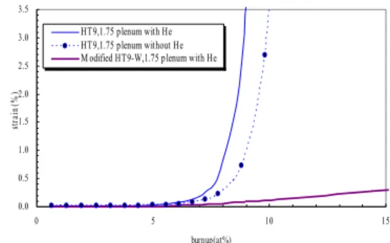
Figure 1 shows the cladding thermal creep strain comparison with the He effects as a function of the plenum-to-fuel ratio for the fuel.
0.0 0.5 1.0 1.5 2.0 2.5 3.0 3.5 0 5 10 15 burnup(at%) st ra in (% ) HT9,1.75 plenum with He HT9,1.75 plenum without He M odified HT9-W,1.75 plenum with He
Figure 1. Thermal creep strain according to the burnup
The value of the thermal creep strain of HT9 without the He effects was about 0.73% at 8.8atom% for the 1.75 plenum-to-fuel ratio. But the value of the strain with the He effects was about 2.53% at 8.8at% for the 1.75 plenum-to-fuel ratio. These results indicate that the He effects will be a very important factor for a higher burnup, even if the loaded 241Am weights are
very small.
According to preliminary burnup limits, the thermal creep strain limit is 1%. In the case of HT9, the burnup limit of the fuel was 8.0atom% for the 1.75 plenum-to-fuel ratio. It was estimated that the HT9 cladding is not conservative for satisfying the discharge burnup goal, because of the high coolant outlet temperature.
Figure 1 also shows the thermal creep strain of the modified HT9. The thermal creep strain of the modified HT9 with the He effects was below 1% at 15atom% for the 1.75 plenum-to-fuel ratio. So it was estimated that
Transactions of the Korean Nuclear Society Autumn Meeting Busan, Korea, October 27-28, 2005
the modified HT9 cladding is conservative for satisfying the discharge burnup goal, because of the high thermal creep resistance characteristics. It is expected that the total strain limits analysis including the irradiation creep and the swelling is required in the case of the modified HT9 cladding.
2.3 Cumulative Damage Fraction Analysis
The strain limits approach has a deficiency in that the rupture strain is strongly dependent on the temperature and strain rate. However, the cumulative damage fraction (CDF) method utilizes the linear life fraction rule assuming that the damage accumulates linearly. The CDF value is determined from the time-to-rupture correlation as a function of the temperature and stress.
Figure 2 shows the data of the creep rupture strength of the modified HT9 claddings[4]. The creep rupture strengths of the modified HT9 claddings were modeled into MACSIS.
1.E+01 1.E+02 1.E+03
1.E+02 1.E+03 1.E+04 1.E+05
Time to ru ptu re (h r) S tre ss (M P a ) HT 9 correlation Modified HT 9 data Modifed HT 9-W data
Figure 2. Time to rupture correlation
For the evaluation of the component reliability, the Weibull statistical model [5] has been widely used in the area of nuclear components as well as other industries. For the steady-state conditions, the probabilistic CDF were estimated as follows;
• The cumulative damage fractions of the X447 fuel pins were evaluated from the time-to-rupture correlation by MACSIS;
• The failure distribution functions of the metallic pins were derived by the Weibull analysis with the application of a CDF and a burnup;
• The fuel pin performances were estimated under the critical system conditions.
Figure 3 shows the cumulative damage fractions of the claddings. Generally the limit on the fuel pin failure rate of the fast reactor core is less than 0.01%. Figure 3 also shows the CDF limit of 0.001 was reasonable for the HT9 cladding.
In the case of HT9, the calculated CDF for the fuel pin during the steady-state was 1.39×10⁻³ at 8.7atom%
for the 1.75 plenum-to-fuel ratio. The fuel pin failure rate was 0.00101%. It was estimated that the burnup limit according to the CDF analysis was about 8.5atom% for the HT9 cladding.
In the case of the modified HT9-Mo without
tungsten, the calculated CDF was 1.1×10⁻³ at
9.31atom%. It was estimated that the burnup limit according to the CDF analysis was about 9.2atom% for the modified HT9-Mo cladding.
In the case of the modified HT9-W with adding tungsten, the calculated CDF for the fuel pin during a steady-state was 9.1×10⁻⁴ at 11.45atom%. It was
estimated that the burnup limit according to the CDF analysis was about 11.5atom% for the modified HT9-W cladding.
0.000001 0.00001 0.0001 0.001 0.01 0.1 1 10 0.00001 0.0001 0.001 0.01 0.1 1 CDF F ailu re P ro ba bility
Weibull distribution for HT9
HT9, 8.7at% Steady-state failure rate limit
Preliminary CDF limit
M odified HT9-M o, 9.31at% M odified HT9-W, 11.45at%
Figure 3. Cumulative damage fraction
3. Conclusion
The design limits of the cladding stress and strain were analyzed by MACSIS. The thermal creep strain of the modified HT9 with the He effects was below 1% at 15atom% for the 1.75 plenum-to-fuel ratio. So it was estimated that the modified HT9 cladding is conservative enough for satisfying the discharge burnup goal. The probabilistic CDF design limits were analyzed for the steady-state conditions. It was estimated that the burnup limit according to the CDF analysis was about 11.5atom% for the modified HT9-W with adding tungsten.
Acknowledgements
This study was supported by the Korean Ministry of Science & Technology through its National Nuclear Technology program.
REFERENCES
[1] B.O.Lee, et al., Analysis on the Temperature Profile and the Thermal Conductivities of the Metalic and the Dispersion Fuel Rods for HYPER, Proceedings of KNS, May (2001). [2] G. L. Hofman, L. C. Walters and T. H. Bauer, Prog. Nucl. Energy, 31, 83 (1997).
[3]M.K. MEYER, et al., Fuel Design for a U.S. Accelerator Driven Transmutation System Nuclear Applications In The New Millenium (AccAPP-ADTTA’01), Reno, Nevada, Nov (2001)
[4]W.S.Ryu et al., High temperature material characterization and advanced materials development, KAERI/RR-2515(2004). [5] Robert B. Abernethy et al., The New Weibull Handbook; 2nd Edition, Gulf Publishing Company (1996).
![Figure 2 shows the data of the creep rupture strength of the modified HT9 claddings[4]](https://thumb-ap.123doks.com/thumbv2/123dokinfo/4967244.52321/2.892.481.785.308.485/figure-shows-data-creep-rupture-strength-modified-claddings.webp)
