As a result, 5-axis machine tools have been widely used in various manufacturing applications that require higher machining accuracy. To overcome these challenges and under the motivation to high-accuracy 5-axis machine tool, modeling and evaluation of the volumetric errors for a 5-axis machine tool was set as this research objective.

INTRODUCTION
Problem Definition
In efforts to reveal these prerequisites, enormous research for identifying and improving the machine tool's volumetric error has been conducted and successfully verified. To improve the machine tool's volumetric accuracy, there are two approaches to minimize the end effect of geometric errors present in each component.
Research Objective
The volumetric error of machine tools can be defined as one of the most important factors affecting the accuracy of a machined part. In this study, in order to simplify the machine tool error modeling, assume that the backlash.
Organization of Thesis
LITERATURE REVIEW
- Kinematic Structure and Systematic Geometric Error of 5-Axis Machine Tools
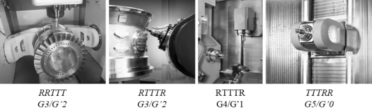
- Classification of Kinematic Structure of 5-Axis Machine Tools
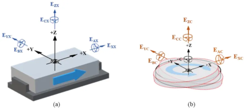
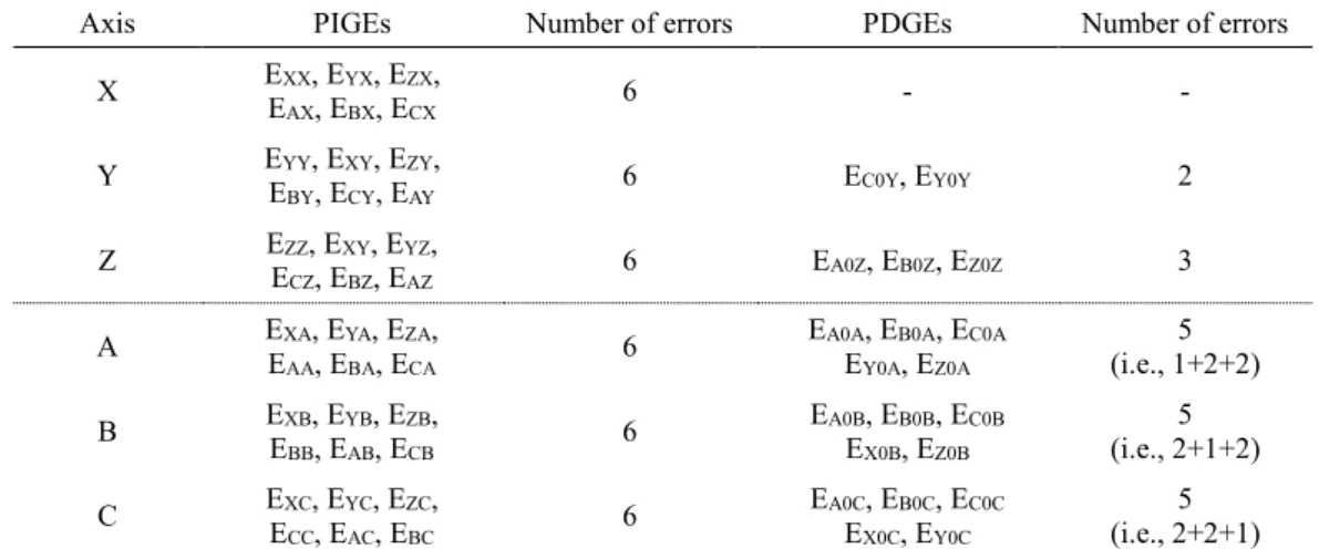
- Classification of Systematic Geometric Error of 5-Axis Machine Tools
- Techniques for Error Modeling of Multi-Axis Machine Tools
- Technique for Measurement of Volumetric Error of Machine Tools
- Summary
In this section, the results of the experiments performed on a 5-axis machine tool are given. To improve the volumetric error of the multi-axis machining tools, an error model for the target machining tool is essential.
![Fig. 2-2 Influencing factors on geometric and kinematic deviations of machine tools[33]](https://thumb-ap.123doks.com/thumbv2/123dokinfo/10493801.0/18.892.239.664.531.803/fig-influencing-factors-geometric-kinematic-deviations-machine-tools.webp)
MODELING VOLUMETRIC ERROR FOR 5-AXIS MACHINE TOOLS
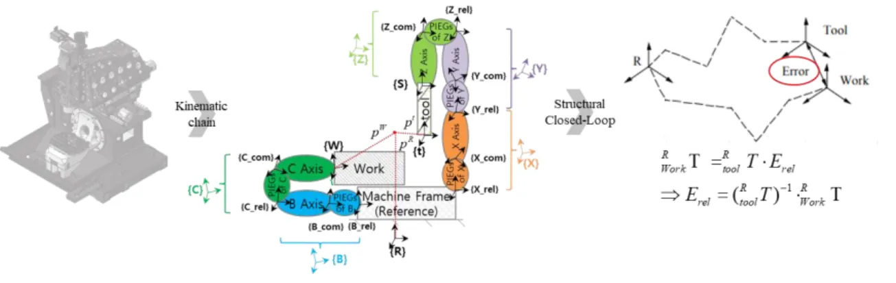
Kinematic Structure and Chain of 5-Axis Machine Tools
3-2 and can be represented as (w)CBFXYZ(t) according to the order of attachment of the part of a workpiece to a tool. Using the fundamental concept of this kinematic chain, the location of a given functional point on a tool tip and a workpiece, Pt and Pw, respectively, can be identified with respect to a reference coordinate frame {R}. One path of the structural kinematic chain loop runs from the reference (fixed) coordinate frame to a given point on the cutting tool coordinate frame, consisting of 3 translational connections, X-axis expressed as {X}, Y-axis expressed as {Y}, Z -axis expressed as {Z}, pivot expressed as {S}.
First, 'T' represents the coordinate transformation, and the workpiece coordinate frame {w} with respect to reference coordinate frame {R} can be described as;. And also, from the nature of the closed loop, coordinate transformations of the cutting tool coordinate frame {t} relative to the reference coordinate frame {R} can be described as;.
Homogeneous Coordinate Representation for 5-Axis Machine Tools
For axes with a sequential combination of motions, such as multi-axis machine tools, the homogeneous transformation matrix (so-called HTM) corresponding to each frame can be serially multiplied to obtain a single HTM form for the resultant motion. Using this homogeneous transformation approach, the machine tool system framework can be decomposed into a set of individual motion components with each coordinate transformation matrix. These matrices describe the relative posture and location (position) between each motion component and any transitional coordinate frames that may be created in the modeling process.
The modeling can start at the cutting tool point or workpiece or reference coordinate frame and can also arrive all the way around to any point at a cutting tool or workpiece coordinate system depending on the starting point. For example, if N rigid bodies are connected serially and the corresponding homogeneous transformation matrices between related motion components (axes) are assigned correctly, the location (position) and orientation (position) of the end point (N. components) in the reference coordinate frame criteria will be estimated as the sequential multiplication of all homogeneous transformation matrix and becomes under;.
Homogeneous Transformation Matrix for 5-Axis Machine Tools
- Homogeneous Transformation Matrix of Linear Motion Components
- Homogeneous Transformation Matrix of Rotary Motion Components
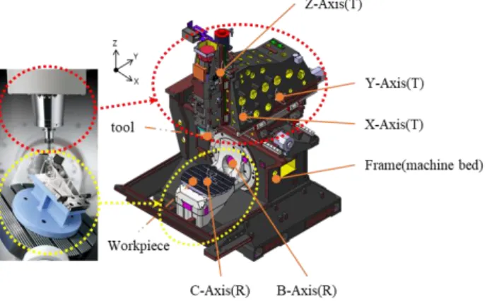
- Homogeneous Transformation Matrix of Errors by Inaccurate Link
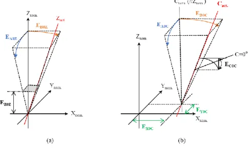
Where, δxX is the X-direction error during X-axis movement and is defined as the positioning error. For reference, each term in the error matrix above is a function of position on the X axis. Where, βXC is the squared error of the C-axis rotation relative to the X-axis motion.
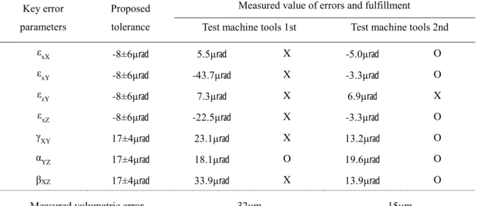
As can be seen from the measurement results, the volumetric error of the test machining tool is 32μm within the entire working space. The measurement result of geometric errors along the X, Y and Z axes, to which the proposed tolerance is applied to improve the volumetric error of the target machining tool, is shown in Fig.
EVALUATION OF VOLUMETRIC ERROR FOR A 5-AXIS MACHINE TOOL
Formulation of Error Model for a Practical 5-Axis Machine Tool
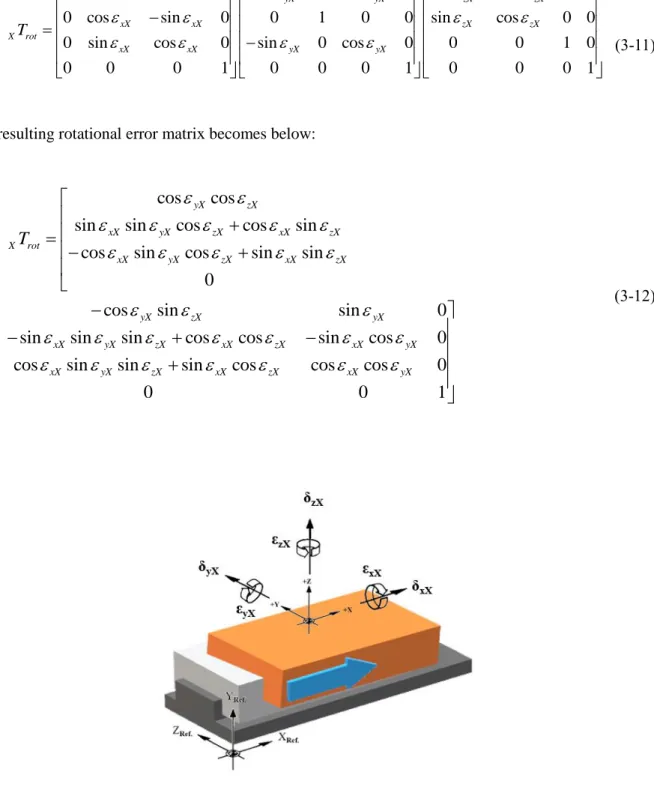
For this purpose, kinematics adopting rigid body motion and homogeneous transformation matrix (HTM) were used for the formulation of the 5-axis machine tool's volumetric error model in this research. The machine bed is chosen as the fixed reference frame, and each functional component is assumed to be a component with a rigid body motion expressed by a capital letter, e.g. 'X' represents the X-axis or 'C' represents the C-axis. The transformation matrix between rigid body 'M' and the adjacent previous-series rigid body 'L' is expressed as;.
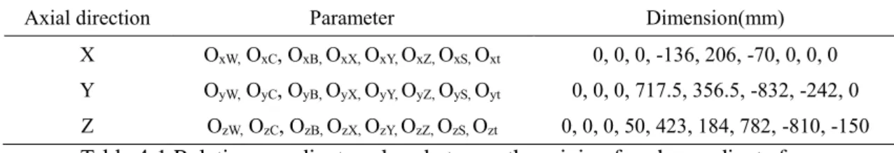
In this regard, the distributions of the coordinate frame in each rigid body that make up the 5-axis machine tool are determined, which is shown in Figure 4-2 Distribution of coordinate frames in each rigid body; (a) Isometric view, (b) Right side view, and (c) Plan view.
Determination of Key Error for a Practical 5-Axis Machine Tool
The outcome of the determination of the analysis for key failure of a 5-axis machine tool, DVF5000, is shown in Fig. The analysis result of sensitive error parameters of a 5-axis machine tool, DVF5000, reveals that the key error factors that propagate to the end point's volumetric error are angular movement and orthogonality (squareness errors) related to the orientation of the movement components. The result of determining the analysis for critical error of rotating components of a 5-axis machine tool, DVF5000, is shown in Fig.
The result of the analysis of the sensitive error parameters of the rotary axes of the DVF5000 5-axis machine tool reveals that, unlike the linear motion axis configuration, the angular error parameters propagated by amplification do not exist in the specific working space of this machine tool. 4-6 Result of analysis of sensitive error parameters for Evx, Evy and Evz rotation axes.
Estimation of Volumetric Error for a Practical 5-Axis Machine Tool
The illustration of the simulation of traces at each tool point affected by the geometric and kinematic error occurring within the tolerance range in the working volume mm3 of this 5-axis machine tool is as shown in figure. And the traces at a certain point corresponding to the allowable height and radius of the maximum workpiece, Ø550 × 450 mm3, which is affected by the geometric and kinematic error occurring within the tolerance range when rotating within the limit of the angle of each rotating part, is as shown in Figure According to the estimation for the volumetric error of the present 5-axis machine tool under the tolerance of the general case, as shown in Table 4-6, the volumetric error of the tool point propagating through the tool sidelobe is predicted to be about 41 μm, and the volumetric error of the workpiece tip propagating through the workpiece sidelobe is predicted to be about 15 μm.
Then, to confirm the effect under the condition of suppressing the critical parameters of the geometric error that propagate sensitively to the end of the functional point, the main error parameters are determined, which are magnified by the distance between the sources of the error and the last functional point. In this regard, the comparison results show that for 4 categories of key errors, the parameters of the 5-axis machine tool material and the effect that can be achieved by inhibiting them, and is shown in Table 4-8.
![Table 4-5 Chance of a value falling within k σ of its expected value for random processes[19]](https://thumb-ap.123doks.com/thumbv2/123dokinfo/10493801.0/58.892.306.588.560.726/table-chance-value-falling-expected-value-random-processes.webp)
EXPERIMENTAL RESULTS AND DISCUSSION
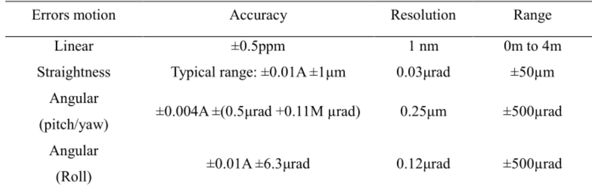
Experiment Setup
And then the beam splitter is placed in the path of the laser beam between the laser emitter and the linear reflector. For example, when there is a squareness error between the movement in the X and Y axis directions, the resulting circular contour on the polar graph is tilted in the X or Y direction, as shown by a typical example of the measured result in the figure. An example of a setup for a circular test of a typical type of vertical machining tool is given in Fig.
5-4, and the figure shows the preparation according to the contour movements of XY, XZ and YZ in order. In this study, therefore, a laser tracker is used as a means of final volumetric error estimation of a 5-axis machining tool to demonstrate the applicability of containment measures for key errors and corresponding volumetric error improvement, an example of a laser tracker setup for volumetric error estimation is given in Fig.
Experiment Results of a 5-Axis Machine Tool, DVF5000
- Assessment for Errors Before Application of Proposed Tolerance
- Assessment for Errors After Application of Proposed Tolerance
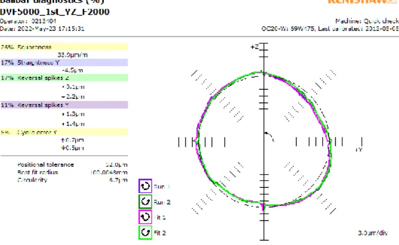
As mentioned earlier, a circular test using a double ball bar was used in a way to confirm the square error of the machining tool under test and an example of the measurement result as shown in Fig. Thus, in order to directly compare the effects of limiting each key error parameter, the volumetric error of the machining tool produced in the condition without the application of optimized tolerances to reflect the kinematic characteristics of this machining tool was confirmed using Lasertracer-MT produced by eTALON, and the result is shown in Fig. Thus, based on the results of this evaluation, the volumetric error of the assembled machining tool with the proposed tolerance is compared in terms of the shape of the three-dimensional space composed of each plane and the level of volumetric error and validity. of the new tolerance is determined through this comparison of differences.
Volumetric error as a comprehensive evaluation index of machining tool errors directly reflects the condition depending on how the machine builder continues to control the error caused by the machining tool movement components during design and assembly. Consequently, the volumetric error of the machining tool produced by applying optimized tolerances to reflect the kinematic characteristics of this machining tool is 15μm over the entire working space, and the result is shown in Fig.
Comparison of Experiment Results and Discussion
It is confirmed that all the main error parameters of processing tool '2' are well managed, that is, well suppressed, compared to processing tool '1'. Therefore, to minimize these errors during the manufacturing process, fine-tuning using dummy loads during assembly and optimizing the shape of the machining surface seems to have been effective. By comparing the perpendicularity for each measuring plane, it is confirmed that the squared error for the '2nd' XY and YZ planes compared to the '1st' is collected under extremely good management.
Therefore, the effectiveness of the square error control for increasing the volumetric error of the processing tool can be distinguished through these comparative experiments of two sample processing tools. Furthermore, it can be seen that not only the change in measurement value, but also the shape of the entire workspace shows a clear change in quality as seen in Fig.
CONCLUSION AND FUTURE WORKS
34;Modeling Geometric and Thermal Errors in a Five-Axis CNC Machine Tool." International Journal of Machine Tools and Manufacture. 34;Identification and Compensation of Systematic Deviations Specific to 5-Axis Machine Tools." International Journal of Machine Tools and Manufacturing. 34; A Methodology for Systematic Geometric Error Compensation in Five-Axis Machine Tools.” The International Journal of Advanced Manufacturing Technology.
34;Proposal for a volumetric error model considering backlash in machine tools." The International Journal of Advanced Manufacturing Technology. 34;Modeling of five-axis machine tool metrology patterns using matrix summation approach." International Journal of Advanced Manufacturing Technology.