저작자표시 2.0 대한민국 이용자는 아래의 조건을 따르는 경우에 한하여 자유롭게
l 이 저작물을 복제, 배포, 전송, 전시, 공연 및 방송할 수 있습니다. l 이차적 저작물을 작성할 수 있습니다.
l 이 저작물을 영리 목적으로 이용할 수 있습니다. 다음과 같은 조건을 따라야 합니다:
l 귀하는, 이 저작물의 재이용이나 배포의 경우, 이 저작물에 적용된 이용허락조건 을 명확하게 나타내어야 합니다.
l 저작권자로부터 별도의 허가를 받으면 이러한 조건들은 적용되지 않습니다.
저작권법에 따른 이용자의 권리는 위의 내용에 의하여 영향을 받지 않습니다. 이것은 이용허락규약(Legal Code)을 이해하기 쉽게 요약한 것입니다.
Disclaimer
저작자표시. 귀하는 원저작자를 표시하여야 합니다.
Doctor of Philosophy
FRICTION STIR ASSISTED JOINING AND FORMING OF DISSIMILAR METALS
The Graduate School of the University of Ulsan
School of Mechanical Engineering
Mounarik Mondal
i
FRICTION STIR ASSISTED JOINING AND FORMING OF DISSIMILAR METALS
Advisor: Professor Sung-Tae Hong
A Dissertation
Submitted to the Graduate School of the University of Ulsan in Partial Fulfillment of the Requirements
for the Degree of
Doctor of Philosophy
by
Mounarik Mondal
School of Mechanical Engineering University of Ulsan, Republic of Korea
November 2021
Dedicated to my family and friends who have supported me the whole way
i
Acknowledgement
First, I would like to express my sincere gratitude to my advisor, Prof. Sung-Tae Hong, for his valuable encouragement and discussions on my Ph. D. study and related research.
Especially the strict academic attitude and conscientious working style have influenced me deeply, which will be of great benefit to me in my future research work.
I particularly wish to thank Prof. Heung Nam Han, Prof. Hoon-Hwe Cho and their students at the Seoul National University and Hanbat National University for their help and valuable advice on my study. Furthermore, it is my pleasure to express my thanks to the rest of my thesis committee: Prof. Koo-Hyun Chung, Prof. Dong-Kyu Kim for their insightful comments and encouragement. Also, I wish to express my appreciation to all colleagues in the Advanced Engineering Materials Laboratory, School of Mechanical Engineering, University of Ulsan for their constant support on my research and experiments. I also thank all those who have helped me in one way or another during my Ph. D. period.
Finally, I really want to express gratitude to my parents, my wife for their continuous encouragement, understanding and support.
Mounarik Mondal Ulsan, Republic of Korea December 2021
ii
ABSTRACT
Enhancement of energy efficiency and to reduce harmful emissions simultaneously, most industries intend to incorporate lightweight multiple materials structures. To construct such structures joining and forming are the basic needs. Further, localized enhancement and use of bi or multi metallic components are also recommended due to lack of stiffness, corrosion property, and poor conductivity for some lightweight non-ferrous metals. The conventional fusion welding techniques induce solidification defects, base material softening, and excessive formation of detrimental intermetallic compounds. Moreover, the preexisting hot forming techniques involve the requirement of external energy, causing prolonged manufacturing time and higher energy consumption.
Friction stir processing (FSP) is a solid-state manufacturing process generating frictional heat, which can evade defects related to solidification and does not require any external energy source. The energy input for this process for dissimilar material combinations especially can be perplexing, and its optimization requires several types of operating parameter variation. Thus, an in-depth study involving microstructural and mechanical property correlation by varying energy input conditions for different material combinations used for forming or joining is required for establishing this process as an alternative to the existing process. To validate the claims, several different combinations of materials are butt and lap spot welded. In addition, the standard FSW processes were also modified to invent a noble process of simultaneous joining and forging of the Al-Mg and Al-Cu bimetallic blanks.
Low nickel austenitic stainless steel (LN1) and 409M ferritic stainless steel is friction stir welded to study the effect of material flow on weld quality and also dynamic recrystallization phenomena by carrying out the electron microscopy. Later it was correlated with the measured mechanical properties. The ferritic stainless steels show more severe dynamic recrystallization, resulting in a very fine microstructure, probably due to the higher
iii
stacking fault energy. Elemental mapping of the dissimilar joints clearly indicates that the material flow pattern during FSW depends on the process parameter combination.
Dissimilar joining of mild steel and aluminum 5052-O aluminum is carried out successfully by offsetting the tool pin towards the harder steel material by 0.5 mm with a convex scrolled tool made of tungsten carbide. 1000 rpm and 75 mm/min weld parameter resulted in better material mixing, which further enhances the mechanical properties of the joint.
1060 pure aluminum was strengthened using a novel technique by combining additive manufacturing and friction stir processing. Additively manufactured 7 series aluminum inside a grooved 1series Al were friction stirred to incorporate more refined grain structure and precipitations of 7 series aluminum resulting dual strengthening. The mechanical properties of the AM+FSP ed sample were enhanced significantly.
The friction stir spot welding process was modified to invent a new simultaneous joining and forming process and was successfully carried out on both Al-Mg and Al-Cu bimetallic blanks to form a bimetallic ring component. The frictional heat generated by the rotating tool forges and the bimetallic blanks generates favorable conditions for diffusion, resulting in joining by intermetallic formation. Since the material combination was altered the composition of the IMC is altered significantly. Due to the poor formability of Mg, the energy required to accomplish the process was much higher. In contrast, due to good formability and high reactivity of Al and Cu, much lower energy input was adequate to carry out the process.
iv
TABLE OF CONTENTS
Page
no.
ACKNOWLEDGEMENTS i
ABSTRACT ii
TABLE OF CONTENTS iv
LIST OF FIGURES vi
LIST OF TABLES x
CHAPTER 1 INTRODUCTION 1
1.1 Research motivation 1
1.2 Need of this research work 3
1.3 Brief introduction of the works 5
References 8
CHAPTER 2 FRICTION STIR ASSISTED DISSIMILAR BUTT JOINING OF DIFFERENT GRADES OF STAINLESS
STEEL ALONG WITH MILD STEEL AND
ALUMINUM 5052-O
11
2.1 Introduction 12
2.2 Experimental setup 15
2.3 Results and discussion 19
2.4 References 38
CHAPTER 3 ENHANCEMENT OF THE MATERIAL PROPERTIES LOCALLY FOR PURE ALUMINUM SHEETS BY A
LINKING ADDITIVE MANUFACTURING AND
FRICTION STIR PROCESSING
44
3.1 Introduction 45
3.2 Experimental set-up 46
3.3 Results and discussion 51
References 60
CHAPTER 4 MANUFACTURING OF MAGNESIUM/ALUMINUM AND COPPER/ALUMINUM BIMETALLIC RING
62
v
COMPONENTS BY FRICTION STIR ASSISTED SIMULTANEOUS FORGING AND SOLID‑STATE JOINING
4.1 Introduction 64
4.2 Experimental set-up 69
4.3 Results and discussion 75
References 102
CHAPTER 5 SUGGESTION FOR DEVELOPMENT OF CURRENT PROCESS
111
CHAPTER 6 SUMMARY AND CONCLUSION 112
vi
LIST OF FIGURES
Fig. No. DESCRIPTION Page No.
1.1 The EU FP6-project super-light car from multiple material 2 1.2 Multi high strength steel Volvo V40 safety cage 2 2.1 Schematic diagram of friction stir butt welding 17
2.2 Schematic representation of experiment 18
2.3 Z force response for travel speed of (a) 50 mm/min and (b) 75
mm/min. 20
2.4 Torque response for travel speed of (a) 50 mm/min and (b) 75
mm/min 20
2.5 Process response (a) Z-force, (b) Torque acquired from FSW
machine 20
2.6 a) Material flow, (b) schematic, (c) enlarged view of region (I), and (d) EPMA of region (II) for Manganese of LN ASS and 409M FSS dissimilar joint for the 1000/50 combination of parameter
23
2.7 (a) Material flow, (b) schematic, (c) enlarged view of region (III), and (d) EPMA of region (IV) for Manganese of LN ASS and 409M FSS dissimilar joint for the 1500/50 combination of parameter
24
2.8 (a) Material flow path and weld cross section for 800/75 combination of parameters (b),(c)& (d) are magnified zones in advancing, central and retreating side as marked in the weld cross section
26
2.9 2.9 (a) Material flow path and weld cross section for 1000/75 combination of parameters (b), (c) & (d) are magnified zones in advancing, central and retreating side as marked in the weld cross section
26
2.10 a) SEM image of the center of SIF with 1000 rpm / 75 mm/min and the results of EDS elemental scan of the region shown in (a):
(b) aluminum and (c) iron; (d) SEM image of the center of PIF with 1000 rpm /75 mm/min and the results of EDS elemental
27
vii
scan of the region shown in (d): (e) aluminum and (f) iron
2.11 SZ and TMAZ of 1000/50 combination of parameter (a) ASS and
(b) FSS side 29
2.12 SZ and TMAZ of 1500/50 combination of parameter (a) ASS and
(b) FSS side 29
2.13 (i) Inverse pole figure maps parallel to welding direction (WD) and (ii) misorientation-angle distributions of base metal: (a) LNASS and(b) 409M FSS, respectively
33
2.14 Phase maps (austenite in green, ferrite in red) parallel to welding direction (WD) of the (a) 1000/50 and (b) 1500/50 combinations;
For the 1000/50 and 1500/50 combinations, the center point of the observation areas was about 370 and 870 μm away from the welded surface, respectively
33
2.15 Pole figures of the 1000/50 and 1500/50 combinations at the regions marked as SZ (AS), SZ (RS) and SZ (center) in Fig. 2.14
34 2.16 (a) The fraction of low angle boundary (LAB), (b) grain size,
and (c) the fraction of coincidence-site lattice (CSL) in austenite as a function of the distance from the weld center line for the 1000/50 and 1500/50 combinations
34
2.17 Microhardness plot of the FSW joints
36 2.18 Vickers microhardness results of weld cross sections for 800/75
and 1000/75 parameters along line 1(b), 2 (c) & 3 (d)
36 3.1 A schematic of AM-FSP: (a) machining of a groove on the
matrix metal (aluminium 1060), (b) AM of aluminium
47 3.2 Cross section of AMed aluminium matrix and (b) magnified view
of the interface (region I)
47 3.3 Cross sections of AM-FSP specimens (a) AM-FSP 2000 / 50, (b)
AM-FSP 1200 / 50, (c) AM-FSP 800 / 50
50 3.4 (a) Cross section of FSP only, (b) Cross section of AM-FSP, (c)
SEM of region [II] as marked in Fig.4 (b), (c) SEM of region [III] as marked in Fig. 5.4(b)
50
viii
3.5 (a) SEM of the region II in Fig. 5.3(a); (b)–(e) EDS mappings of the region II, and (f) point analysis of P1, as marked in (a)
52 3.6 (a) SEM of region III in Fig. 5.3(a); (b)–(c) EDS mappings of the
region II, and (d) point analysis of P2, as marked in (a)
52 3.7 (a) Cross section of the AM-FSP specimen; IPF, HAB & LAB
maps of (b) the base metal, (c) the onion ring structure (region V), and (d) the MER (region VI)
54
3.8 Microhardness profiles for the AM-FSP and FSP-only specimens 56 3.9 Stress strain curves for the AM-FSP specimen (along the tool
travel direction) and the base metal
56 3.10 An application of AM-FSP to locally reinforce sheet metal
product for enhanced stiffness: (a) sheet metal forming, (b) sheet metal product with a groove along the perimeter, (c) AM inside the groove, and (d) FSP along the groove filled by AM to enhance the structural stiffness
57
4.1 (a) Schematic of a Mg/Al bimetallic blank, (b) cylindrical FS- forging tool with a two-step shoulder and a die with a cylindrical cavity
71
4.2 (a)–(d) FS-forging stages, (e) a forged blank and a bimetallic ring 71 4.3 (a) A schematic of an Mg/Al bimetallic blank, (b) cylindrical FS-
forging tool with a two-step shoulder and a die with a cylindrical cavity
72
4.4 Deformation of a Mg/Al blank during FS-forging 73
4.5 Force and torque histories of FS-forging 77
4.6 Deformation of a Mg/Al blank during FS-forging 77 4.7 Optical microscopic image of a forged bimetallic blank 80 4.8 OM observation on the cross sections of final ring components,
b, d, f SEM Images of region i, ii, and iii marked in (a), c, e, g corresponding element line-scanning spectrums
80
4.9 EBSD analysis of base metals: IPF and KAM maps 83
ix
4.10 EBSD analysis of FS-forged Mg/Al bimetallic ring with the parameter set 1400/8: a cross section; b IPF and c KAM of the white box region; d, e magnified images of the areas of the Mg core, Al skin, and their interface marked by black boxes in (b, c)
83
4.11 Hardness profiles along the middle of the cross-section in the radial direction for two different sets of parameters
84
4.12 Force and torque histories of FS-forging 86
4.13 (a) simultaneously forged and joined cross section of 800/15, (b, c, bi, ci) SEM and EDS line scanning of the marked regions [i]
and [ii]
88
4.14 (a) simultaneously forged and joined cross section 550/15, (b, c, bi, ci) SEM and EDS line scanning of the marked regions [i] and [ii]
89
4.15 (a) – (c) EDS area mapping 95
4.16 (a1) - (a3) and (b1) – (b3) represents IPF, KAM HAB and LAB maps for copper and aluminum
97 4.17 (a1) - (a3), (b1) – (b3), (c1) – (c3) represents IPF, KAM HAB
and LAB maps for copper, aluminum, joining of Al -Cu
97 4.18 Microhardness plot
99
x
LIST OF TABLES
Table No. DESCRIPTION Page No.
2.1 Chemical compositions of base materials (wt. %) 17
2.2 Mechanical property of base materials 17
2.3 Welding parameters and calculated energy input 17
2.4 Tool geometry 17
2.5 Process parameters and Energy input 18
2.6 Chemical composition of 5052-O (wt. %) 18
3.1 Chemical compositions of aluminum 7075 alloy powder
(wt. %). 48
3.2 Parameters for additive manufacturing 48
3.3 Fraction of HAB in matrix metal and the SZ 54
4.1 Alloying elements of AZ31B and Al6061-T6 (wt.%) 72
4.2 Fs- forging parameters 72
4.3 Chemical composition of the Al and Cu 73
4.4 FS-forging process parameters 73
4.5 Chemical composition at different positions in Fig. 4.7 b, d,
and f 81
4.6 EDS point analysis (at%) of point A, B, C, D as shown on
Fig. 4.15 (b) 94
4.7 Electrical resistivity of various intermetallic compounds 94 4.8 Standard enthalpy of formation of Al/Cu compounds 94 4.9 Calculated effective enthalpy of formation of Al/Cu
compounds 94
1 CHAPTER 1 INTRODUCTION 1.1Research motivation
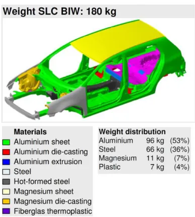
In recent times, most manufacturing industries producing structural engineering products face two different problems: lightweight manufacturing structures for emission reduction and energy efficiency simultaneously manufacturing those faster. In these circumstances, most industries use lightweight materials like aluminum, magnesium, and titanium or their composites as they possess low density and high strength to weight ratio [ Helen N et al.,1995; Suresh M et al.,2011; Hong S-T et al.,2018]. Nevertheless, these materials' lack of stiffness and strength cannot replace steel structures completely. These low stiffness materials can be strengthened by altering their grain sizes, incorporating high hardness particles, or combining both. However, to avoid complex material process routes, many manufacturing sectors directly choose bimetallic or multi-metallic structures for manufacturing lightweight structures. The EU FP6–project Super- light car is a typical multi-material structure, as shown in Fig 1.1. By following this route, light issues related to a single material can be avoided. In addition, using advanced or ultra-high- strength steels (AHSS/UHSS) where the strength of the material is nearly above 1 Gpa, the weight reduction for the structures is achieved by reducing material consumption. The Volvo V40 car is made from multiple grades of high-strength steel, as shown in Fig. 1.2 is an atypical example of the usage of UHSS and AHSS [Mondal M et al.,2019; Das H et al.,2018; Das H et al.,2018; Bae JH et al.,2011].
2
Figure 1.1 The EU FP6–project super-light car from multiple materials
Figure 1.2 Multi high strength steel Volvo V40 safety cage
3 1.2 Need of this research work
To manufacture these lightweight structures and components, joining and forming dissimilar materials are necessary. In most cases, small parts are formed first and then
joined together using conventional joining techniques. Thus, manufacturing of these lightweight structures is manufactured in two steps which consume more energy and time. Hence simultaneous joining forming processes to manufacture lightweight structures is desired to reduce time consumption. Especially in most automobile structures, incorporating UHSS or AHSS is carried out where welding is necessary. Inside the automobile structures, at least 300 spot welding is carried out, and sometimes butt joining is carried for joining tailored blanks.
RSW being a rapid fusion welding technique also induces brittle microstructure inside the welding, which further reduces high cycle fatigue of the materials and, in some cases, reduces the weld efficiency [Ng MK et al.,2015; Napierala O et al.,2019; Aldanondo E et al.,2013;
Dilthey U et al.,2006; Kong JP et al.,2014]. According to the engineering relevance, joining dissimilar lightweight materials is also considered the most challenging due to the difference in thermomechanical properties, chemical composition, and oxidation behavior. The common welding carried out to join materials is mostly the fusion welding process. Common fusion welding techniques mainly practiced are gas metal arc welding (GMAW), tungsten inert gas welding (TIG), laser welding, and resistance welding. The fusion welding technique involves melting base materials and, in some cases, incorporating filler materials; the joining between two materials is achieved by solidifying the base and filler materials. Thus, the most common defects that arise from the fusion joining are the defects related to the solidification, such as coarse cast structure of the grains inside the weld, solidification cracking in the weld bead or at the
4
transverse direction, generation of tensile residual stress [Sarkar R et al.,2015; Pouranvari M et al.,2011; Majlinger K et al.,2016; Kong JP et al.,2014].
The severity of the existing problem magnifies even further when the fusion joining techniques are used to join dissimilar materials. The joining of different materials mostly takes place by the formation of intermetallic compounds (IMC). These IMC compound are detrimental to the welding quality as it induces brittleness inside the weld material. The IMC can deteriorate material properties like conductivity, corrosion resistance, and overall strength. The formation of these IMC is caused mainly by the interdiffusion of two metals coming in contact and reacting.
The excess heat generated during the fusion welding techniques enhances the interdiffusion, further promoting the formation of the IMCs [Das H et al.,2014; Kreimeyer M et al.,2002].
Solid-state joining is often prescribed for joining dissimilar material combinations and ultra-high-strength steels to counter these problems. Various solid-state welding techniques are used for joining dissimilar materials, such as friction stir welding, activated bonding, abrasion circle, friction spot welding, cold metal transfer, laser penetration welding, and barrel nitriding process. Among all the joining techniques mentioned above, friction stir welding (FSW) does not require high pressure or vacuum chamber. Therefore, FSW can be easily applied inside the assembly plant for both continuous and spot welding processes.
Friction stir welding (FSW) patented by The Welding Institute (TWI) of UK in 1991 as a Solid-state joining procedure and was predominantly applied to aluminum alloys. The rudimentary concept of FSW is straightforward. The abutting edges of sheets or plates to be joined are acted upon with a specially designed pin and shoulder; a non-consumable rotating tool is inserted into and traversed along the line of joint (Fig. 1). The tool work for two primary actions: (a) heating of the base material and (b) movement of material to produce the joint. The
5
joining mechanism in butt FSW mainly involves intermixing plastically deformed materials in the stir zone (SZ). Inside the SZ, high temperature and strain rate generally leads to dynamically recrystallized fine grain structure formation, enhancing the joint's mechanical properties.
Compared to other solid-state joining techniques, FSW generates a more refined grain structure, causes lower residual stress, and consumes energy more effectively. It is considered a ‘‘green’’
technology due to its energy efficiency, environment friendliness, and versatility. FSW does not require filler metal use; therefore, any aluminum alloy can be joined without concern for the compatibility of composition, which is an issue in fusion welding. Since there is no melting involved in the process and welding occurs at the solid-state, it successfully eliminates the defects originating from solidification. Due to lower heat input, the quantities of the IMC forming inside the welding during dissimilar metal joining are also significantly reduced [Mondal M et al.,2017; Rai R et al.,2011; Thomas WM et al.,1997].
1.3 Brief introduction of the works
In this work, friction stir technology is applied to weld and form dissimilar materials combinations and is divided into six chapters as six different works. The six other chapters describe various applications of the material used and discuss in detail the usefulness of the FSW application carried out upon them by correlating mechanical properties of the joint with the microstructural characteristics.
Chapter 2 mainly presents an experimental investigation on FSW of dissimilar stainless steels, low nickel austenitic stainless steel, and 409M ferritic stainless steel. Evaluation of the process responses during FSW and their resultant microstructures of the dissimilar joints are examined. Elemental mapping was used to investigate the in-detail material flow in the stir zone.
It was found that the material movement type in course of FSW depends on the process
6
parameter combination. Dynamic recrystallization and recovery are also seen in the dissimilar joints. Among the two different stainless plates of steel selected in the present study, the ferritic stainless-steel shows more severe dynamic recrystallization, developing in a very fine microstructure, probably due to the higher stacking fault energy. The FSW of aluminum 5052-O alloy and mild steel sheets have been conducted by altering the process parameters in butt configuration with an offset of the tool pin towards the steel sheet at the advancing side. The joint cross-section was briefly analyzed with the aid of optical microscopy and a microhardness indentation test.
Chapter 3 deals with a new technique combining metal AM and MMC formation by FSP is suggested to enhance the material properties of a metal alloy locally. The idea's feasibility is confirmed by the local strengthening of a non-heat-treatable aluminum alloy sheet through AM of an aluminum powder capable of precipitation hardening, followed by FSP.
Chapter 4 describes a newly invented application for FSW where friction stir spot welding was modified to generate friction stir forging, which further simultaneously join and form Al and Mg inside a die. The process was deeply analyzed and described in detail by carrying out optical and electron microscopy. The investigation revealed that the generation of an IMC layer formed the joining between the Al and Mg due to the diffusion between the metals.
The frictional heat generated successfully softens the materials simultaneously; it also creates the driving force for the atoms to diffuse and form an IMC layer to form the joint. Simultaneous joining and forging were carried out on Al and Cu. The forging and joining mechanism were just the same as the Al-Mg work. In this study in-depth study on the evolution of the IMC was carried out to determine the order of formation of the IMC and how it further affects the electrical conductivity of the final finished product. The fast forming and joining technique
7
proved to be an energy-efficient process as it induces CuAl2 IMC with the highest possible electrical conductivity in an Al-Cu bi-metallic component.
8 REFERENCES
1) Helen N. Han and Joel P. Clark, Lifetime Costing of the Body-in-White: Steel vs Aluminum The Journal of The Minerals, Metals & Materials Society May 1995, 22-28.
2) Suresh M, Srinivasan A, Pillai UT, Pai BC. The effect of charcoal addition on the grain refinement and aging response of magnesium alloy AZ91. Materials Science and Engineering:
A. 2011 Nov 15;528(29-30):8573-8.
3) Hong S-T, Das H, Chun DM, Oh HS, MNEAA Nasim (2018) Combination of Nanoparticle Deposition System and Friction Stir Spot Welding for Fabrication of Carbon/Aluminum Metal Matrix Composite Joints of Dissimilar Aluminum Alloys. CIRP Annals 66(1):261–264.
4) Mondal M, Das H, Hong ST, Jeong BS, Han HN. Local enhancement of the material properties of aluminium sheets by a combination of additive manufacturing and friction stir processing. CIRP Annals. 2019 Jan 1;68(1):289-92.
5) Das H, Mondal M, Hong ST, Chun DM, Han HN. Joining and fabrication of metal matrix composites by friction stir welding/processing. International Journal of Precision Engineering and Manufacturing-Green Technology. 2018 Jan;5(1):151-72.
6) Das H, Mondal M, Hong ST, Lim Y, Lee KJ. Comparison of microstructural and mechanical properties of friction stir spot welded ultra-high strength dual phase and complex phase steels.
Materials Characterization. 2018 May 1;139:428-36.
7) Bae JH, Rao AP, Kim KH, Kim NJ. Cladding of Mg alloy with Al by twin-roll casting.
Scripta Materialia. 2011 May 1;64(9):836-9.
8) Ng MK, Li L, Fan Z, Gao RX, Smith III EF, Ehmann KF, Cao J. Joining sheet metals by electrically-assisted roll bonding. CIRP Annals. 2015 Jan 1;64(1):273-6.
9
9) Napierala O, Dahnke C, Tekkaya AE. Simultaneous deep drawing and cold forging of multi- material components: draw-forging. CIRP Annals. 2019 Jan 1;68(1):269-72.
10) Aldanondo E, Taboada A, Arruti E, Alvarez P, Echeverria A. Friction stir spot welding of DP1200 steel. InProceedings of the 1st international joint symposium on joining and welding 2013 Jan 1 (pp. 179-182). Woodhead Publishing.
11) Dilthey U, Stein L. Multimaterial car body design: challenge for welding and joining.
Science and Technology of Welding and Joining. 2006 Mar 1;11(2):135-42.
12) Kong JP, Han TK, Chin KG, Park BG, Kang CY. Effect of boron content and welding current on the mechanical properties of electrical resistance spot welds in complex-phase steels. Materials & Design (1980-2015). 2014 Feb 1;54:598-609.
13) Sarkar R, Sengupta S, Pal TK, Shome M. Microstructure and mechanical properties of friction stir spot-welded IF/DP dissimilar steel joints. Metallurgical and Materials Transactions A. 2015 Nov;46 (11):5182-200.
14) Pouranvari M, Mousavizadeh SM, Marashi SP, Goodarzi M, Ghorbani M. Influence of fusion zone size and failure mode on mechanical performance of dissimilar resistance spot welds of AISI 1008 low carbon steel and DP600 advanced high strength steel. Materials &
Design. 2011 Mar 1;32(3):1390-8.
15) Májlinger K, Kalácska E, Spena PR. Gas metal arc welding of dissimilar AHSS sheets.
Materials & design. 2016 Nov 5;109:615-21.
16) Kong JP, Han TK, Chin KG, Park BG, Kang CY. Effect of boron content and welding current on the mechanical properties of electrical resistance spot welds in complex-phase steels. Materials & Design (1980-2015). 2014 Feb 1;54:598-609.
10
17) Das H, Jana SS, Pal TK, De A. Numerical and experimental investigation on friction stir lap welding of aluminium to steel. Science and Technology of Welding and Joining. 2014 Jan 1;19 (1): 69-75.
18) Kreimeyer M, Sepold G. Laser steel joined aluminium-hybrid structures. In Proceedings of ICALEO 2002 (Vol. 2).
19) Mondal M, Das H, Ahn EY, Hong ST, Kim MJ, Han HN, Pal TK. Characterization of friction stir welded joint of low nickel austenitic stainless steel and modified ferritic stainless steel. Metals and Materials International. 2017 Sep;23(5):948-57.
20) Rai R, De A, Bhadeshia HK, DebRoy T. friction stir welding tools. Science and Technology of welding and Joining. 2011 May 1;16(4):325-42.
21) Thomas WM, Nicholas ED. Friction stir welding for the transportation industries. Materials
& design. 1997 Dec 1;18(4-6):269-73.
22) Lohwasser D, Chen Z, editors. Friction stir welding: From basics to applications. Elsevier;
2009 Dec 18.
11 CHAPTER 2
FRICTION STIR ASSISTED DISSIMILAR BUTT JOINING OF DIFFERENT GRADES OF STAINLESS STEEL ALONG WITH MILD STEEL AND ALUMINUM 5052-O ABSTRACT
Dissimilar friction stir welding (FSW) of stainless steels, low nickel austenitic stainless steel, and 409M ferritic stainless steel are experimentally investigated along with mild steel and aluminum 5052-O alloy. Process responses throughout FSW and the microstructures of the subsequent dissimilar joints are assessed. Material flow in the stir zone is examined in detail by elemental mapping and optical microscopy. Basic mapping of the different joints indicates that the material flow pattern during FSW depends on the process parameter combination. In the case of aluminum and steel joints, intermetallic compounds were also formed. Dynamic recrystallization and recovery are also detected in the dissimilar joints. Among the two different stainless sheets of steel selected in the present study, the ferritic stainless steels show additional severe dynamic recrystallization, resulting in a very fine microstructure, probably due to the higher stacking fault energy.
KEYWORDS: dissimilar stainless steels, friction stir welding, microstructure, texture, electron backscattered diffraction
12 2.1. Introduction
Price and engineering requirements have headed to the development of low nickel austenitic stainless steel (LNASS), which has a high quantity of manganese (5-10 wt. %) with a small percentage of nickel (1 wt. %) and 1200-1600 ppm nitrogen. The formation and stability of the austenite increase by incorporating nitrogen. Thus, LNASS shows a combination of high strength, ductility, and toughness. Ferritic stainless steel (FSS) has good weldability, excellent stress corrosion cracking resistance, and adequate high-temperature endurance to oxidation. FSS has been extensively employed in chemical plants and automotive exhaust structures due to these advantages [Cho HH et al., Lakshminarayanan AK et al., Sainas S et al.]. The environmental and energy efficiency concerns compel multi-material and hybrid structures in transportation industries. These new structures commonly used lightweight alloys like aluminum or magnesium alloys in their parts to reduce overall weight for lowering fuel consumption and toxic emissions.
Engineering relevance involves joining aluminum alloy and steels as an essential dissimilar fabrication requirement for manufacturing multi-material structures [Tang J et al.,2017; Hussein SA et al.,2015].
Dissimilar material welding is of great interest for academia and industry and is used to save costs and reduce material consumption. Due to the significantly different thermo-physical properties, such as thermal conductivity and coefficient of thermal expansion, metallurgical characteristics, and other physical properties, joining aluminum alloy and steels by conventional fusion joining process is extremely difficult. The tremendously low solubility of Fe in Al results in the development of brittle and extreme Al-rich FexAly intermetallic compound (IMC) phases;
these phases are generally unfavorable to the mechanical properties of the joint [Das H et
13
al.,2014]. In this regard, Kreimeyer and Sepold [Kreimeyer M et al.,2002] recommended that if the IMC layer is fewer than 10 μm thick, the joint may have good mechanical properties.
Klueh et al. investigated the fusion welding of austenitic and ferritic dissimilar steels and reported that most weld failures were observed at the ferritic side. They claimed that the primary reasons for the loss might be cyclic thermal stresses, low oxidation resistance with carbon migration, and metallurgical worsening caused by higher temperatures [Klueh RL et al., King JF et al.].
Friction stir kneads welding, [Geiger M et al.,2008] friction welding, [Sahin M et al.,2009; Taban E et al.,2010] surface activated bonding, [Howlader MM et al.,2010] abrasion circle friction spot welding, [Chen YC et al.,2012] cold metal transfer,[ Cao R et al.,2013] laser penetration welding,[ Chen S et al.,2014], barrel nitriding process usually practiced for joining [Kong JH et al.,2014] aluminum alloys to steels. Between the mentioned joining methods, friction stir welding (FSW) does not require high pressure or vacuum chamber. Hence, FSW can be easily carried out inside the assembly plant for continuous but and spot-welding processes [Hou X et al.,2014]. Friction stir welding (FSW), a solid-state joining procedure patented by TWI in 1991 [Thomas WM et al.], has offered excellent welding quality in joining aluminum or magnesium alloys. The accomplishment of FSW for these light metal alloys and different grades of high-strength steels has led to an interest in joining dissimilar stainless steels. Various researchers [Reynolds AP et al., Sato YS et al., Sato YS et al.] performed FSW on 304 and 304L stainless steels. They found that the stir zone undergoes dynamic recrystallization due to the intense deformation with the sigma phase in the advancing side of the stir zone. Comparable microstructural observations were reported by Miyano et al. during FSW of high nitrogen stainless (HNS) steel using the Si3N4 tool. Cho et al. reported the recrystallized microstructural
14
inside the SZ of 409 FSS joints. They studied that increasing the plunging depth enhanced the amounts of plastic deformation and improved the fraction of the low-angle boundary (LAB).
Park et al. studied FSW of 430 FSS and reported a magnificent recrystallized grain structure in the stir zone, resulting in improved tensile strength. Cho et al. conducted a microstructural evaluation of FSW of API grade X100 line pipe steel. They found that various grain structures developed through joints through a complex process that included rearranging low-angle grain boundaries in the stir zone and the thermo-mechanically affected site due to continuous dynamic recrystallization and phase transformation. Haijan et al. investigated friction stir processing (FSP) of 316L stainless steel, and they claimed that the stir zone was mostly dominated by discontinuous dynamic recrystallization. FSW in butt position of thin sheets of aluminum 6061- T6 alloy and advanced high strength steel was conducted by Liu et al. [Liu X et al.,2014]. They evaluated the impact of process parameters on the joint microstructure evolution based on the mechanical welding force and temperature measured during the welding process. Also, Coelho et al. [Coelho RS et al.,2012] investigated the influence of a different high strength steel base material on weld efficiency of FSW of aluminum alloy to the high strength steel. They determined that the joint efficiency depended on the mechanical properties of the heat-affected zone (HAZ) and the aluminum alloy's thermo-mechanical affected zone (TMAZ).
As a concise description above, most of the research paper focused on the microstructure and mechanical properties of FSW joints of similar stainless steels. Unfortunately, FSW of dissimilar stainless steels has only rarely been investigated. Further FSW of aluminum 5052-O alloy and mild steel sheets has been conducted by altering the process parameters in butt configuration with the offset of the tool pin towards the steel sheet at the advancing side. The
15
cross-section of the joint was briefly analyzed with the aid of optical microscopy and microhardness indentation test
2.2 Experimental set-up
The materials used were 409M ferritic stainless steel (FSS), which is also commercially designated as 409M [47], and low nickel austenitic stainless steel (LNASS), commercially set as LN1 [46]. The 409M FSS and LNASS sheets (2 mm thick) were cut to (150 100) mm for the FSW butt joints. The two different base metals' chemical compositions and mechanical properties are listed in Tables 2.1 and 2.2, individually. In the course of FSW, the 409M FSS, which possesses a relatively lower strength, was placed on the retreating side, and the LNASS, with somewhat higher stiffness, was placed on the advancing side, as schematically described in Fig. 2.1. The most appropriate material flow is that ‘material from the retreating side is pulled through the weld centerline and accumulated on the advancing side [Cho HH et al.]. A custom- made friction stir welding machine (RM1A-0.7, MTI, USA) produced all the FSW butt joints by means of the process parameters listed in Table 2.3. The Z force and torque, and depth of penetration were recorded simultaneously in the course of every welding process utilizing a load cell connected with a DAQ system. A polycrystalline boron nitride (PCBN) tool was applied during the course of the experiment, and the convex scrolled shoulder geometry of this tool is recorded in Table 2.4.
The joint tensile strength was evaluated using transverse sub-size tensile specimens according to the ASTM E8M-04 standard in a 100 kN universal testing machine (INSTRON 8862, Instron, UK) at a strain rate of 0.003 s−1. Optical microscopy was conducted using an optical microscope (A1m Axio Imager, Carl Zeiss, Germany) at different magnifications.
16
Electron backscatter diffraction (EBSD) analysis was performed using an FE-SEM equipped with an EBSD system (FESEM: SU70, EBSD: Hikari EBSD detector with TSL OIM 6.1 software, Hitachi, Japan). Specimens for the EBSD analysis were prepared by a standard metallographic grinding technique, followed by electro polishing with an electrolyte consisting of 10% perchloric acid and 90% ethanol. The accelerating voltage was 15 kV, and the working distance was 15 mm for the EBSD analysis. The mapping grid was a regular square of 0.25 × 0.25 μm2 and 1 × 1 μm2 for specimens with rotational tool speeds of 1000 and 1500 rpm, respectively. The critical misorientation angle was set to 15o for grain identification. An electron probe micro analyzer (EPMA) (JXA-8230, JEOL, Japan) with a PC-based operating system was used for elemental mapping
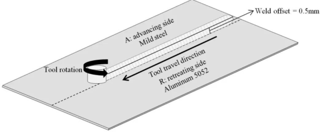
Mild steel (at the advancing side) and aluminum 5052-O alloy (at the retreating side) were butt welded in displacement-controlled mode employing a custom-made FSW machine (RM1A, MTI, USA),. as schematically shown in Fig. 4.1. Both the sheets were of 2 mm thickness each The process parameters for FSW are listed in Table. 4.1 Note that the welding was performed by shifting the tool to an extent of 0.5 mm towards the steel sheet side at the advancing side. It has been reported that offsetting the tool to an aluminum alloy side serves as a better method to protect the tool from wearing during FSW of steels and aluminum alloys.
However, in that case, researchers also reported no trace of material intermixing inside the SZ [Lee WB et al.,2006; Tanaka T et al.,2009]. Material mixing, an essential aspect for judging joint strength, was better in this present study due to the insertion of the tool into the steel side.
The recorded axial force and torque histories in the data acquisition system attached to the FSW machine were first analyzed to calculate the energy contribution. Then, to witness the material movement within the SZ, the cross-section perpendicular to the welding direction was
17
Table 2.1 Chemical composition of base materials
C Si Mn P S Cr Ni Mo Cu Nb Al N Fe
LNASS
(LN1) 0.06 0.23 9.04 0.04 0.01 15.76 0.92 0.001 2.00 0.01 - 0.1 Bal 409M FSS
(409 M) 0.03 0.46 0.79 0.02 0.01 11.10 0.31 0.033 0.02 0.01 0.01 0.03 Bal Table 2.2 Mechanical property of base materials
Base Materials UTS (MPa) YS (MPa) Elongation (%)
LNASS
(LN1) 795 369.41 84.3
409M FSS
(409 M) 522 312.2 29.8
Figure 2.1 Schematic diagram of friction stir butt welding Table 2.3 Welding parameters and calculated energy input
Tool rotational speed (rpm)
Welding speed (mm/min)
Dwell time
(S) Tilt angle ()
Depth of penetration
(mm)
Energy input (kJ)
1000 50
2 1.5 1.9
189.4
1500 50 351.9
75 266.3
2000 75 386.3
Table 2.4 Tool geometry PCBN tool geometry
Shoulder diameter 14.3 mm
Probe length 2 mm
Shoulder Type Convex scrolled shoulder
18
Figure 2.2 Schematic representation of experiment Table 2.5 Process parameters and Energy input Tool rotation
speed (rpm)
Toll travel speed (mm/min)
Tool tilt angle
() Depth of
penetration (mm)
Energy input (KJ) 1000
75 2 1.9 158.7
800 123.6
Table 2.6 Chemical composition of 5052-O (wt. %) Alloying elements
(%) Si Fe Mn Mg Zn Ti Cr Al
5052-0
(ISO AlMg2.5) 0.6 0.5 0.1 0.5 0.2 0.1 0.25 Bal
19
arranged by polishing and etching with Keller’s and Nital etchant for both aluminum and mild steel. Optical microscopy (OM; A1m Axio Imager, Carl Zeiss, Germany) with a load of 0.49 N for 10 seconds was then carried on the cross-section. For the estimation of mechanical properties of the joint, Vickers hardness was determined along the cross-section using a fully standardized Vickers Microhardness tester (A-1170, Leica, Germany).
2.3. Results and discussion
2.3.1. Force and torque response analysis
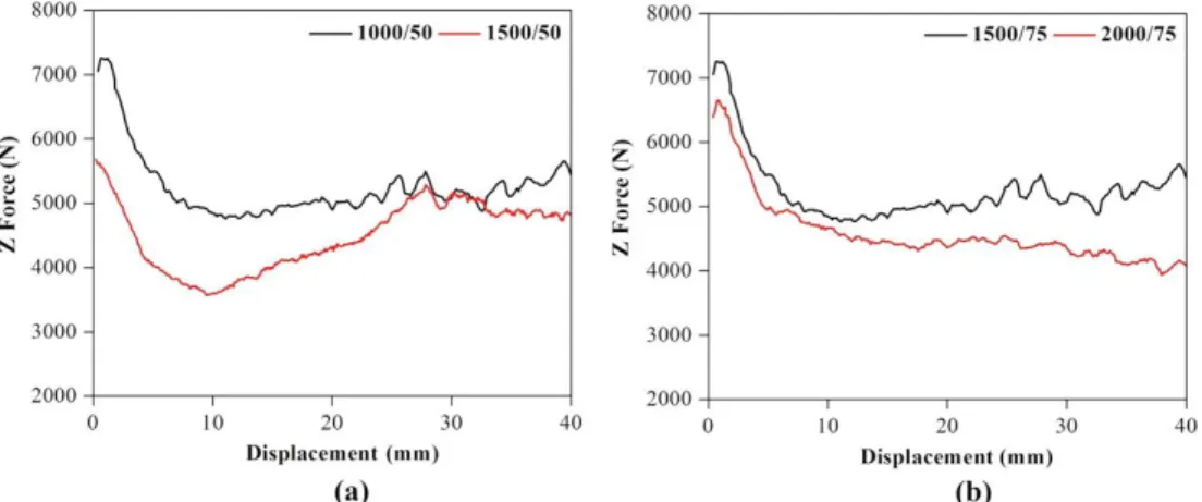
Process responses (axial force and torque) are of great interest during FSW. They depend on the mechanical interactions between the shoulder and candidate materials [Santella M et al., Das H et al.]. Also, these responses depend on the movement pattern of the material throughout the pin and shoulder's stirring action resulting in plasticization/thermal softening. Consequently, perception of the process responses is essential for interpreting the FSW process. As the tool rotational speed increases, the deformation and the frictional heat generation increase, and the material thermally softens more rapidly. The welding process proceeded at the same tool travel speed at a lower axial force with a higher tool rotational speed, as shown in Figs. 2.3 (a) and (b).
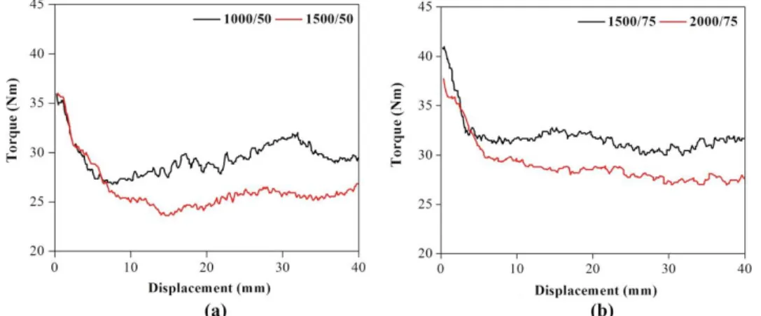
Note that the axial force evolution is the workpiece material response to the applied processing parameters [Santella M et al.]. It is noticed that the torque decreases with an increase in the rotational tool speed (Figs. 2.4 (a) and (b)). The decrease in the torque with increasing tool rotational speed suggests the modification of material flow around the tool due to higher heat input, which changes the viscous material characteristics. The energy input for the period of FSW performs a crucial role in material softening, material flow, and microstructure formation.
The process responses in Fig.2.3 and Figs. 2.4 can be used to approximate the energy input during FSW as shown below [Das H et al., Zimmer S et al.].
20
Figure 2.3. Z force response for travel speed of (a) 50 mm/min and (b) 75 mm/min.
Figure 2.4 Torque response for travel speed of (a) 50 mm/min and (b) 75 mm/min
Figure 2.5 Process response (a) Z-force, (b) Torque acquired from FSW machine
21
Cz and Np correspond to the torque and the tool rotation speed (in rpm). The energy input values calculated using the above equation are listed in Table 2.3. The material flow and micrographs have been studied for four combinations of process parameters. However, to discuss the metallurgical aspects compactly, the remaining part of the manuscript will discuss the results of 1000/50 and 1500/50 combinations only.
Boosting the tool rotation speed from 800 to 1000 rpm maintains a constant weld speed of 75 mm/min together, the axial force and spindle torque reduce drastically. The force and torque descriptions documented during the FSW exhibit that the frictional heat increases enormously with the intensification in tool rotation speed at the constant weld speed; this impacts the plasticization of the materials. From the process responses in Fig. 2.9, the heat input through FSW can be approximated using the relation stated above.
2.3.2. Material flow behavior
The material flow behavior for the process parameter combination of 1000/50 was studied by optical microscopy (Fig. 2.10 (a)), and a schematic of the material flow is portrayed in Fig. 2.10 (b). In the material flow schematic (Fig. 2.10 (b)), the material flow of 409M FSS (in red) is indicated by yellow arrows, and green arrows indicate the material flow of LNASS (in blue). Fig. 2.10 (a) shows that the shoulder influence area is restricted to the top of the weld cross-section. This area promotes the transport of the FSS material from the retreating side to the advancing side of the joint. The quantity of FSS dragged from the retreating side to the advancing side of the joint diminished drastically under the tool pin. In the region under the tool pin, the bulk of the LNASS was extruded from advancing side and moved down to the lower part of the pin-influenced area due to the lower rotational speed and the lower resulting energy input.
22
The bulk LNASS mixed with the FSS, creating a semi-elliptical banded zone with relatively higher hardness values. However, when the materials push upwards under the tool pin, the elongated LNASS (depicted by green arrows) hinders the material flow to the upper region of the joint. The LNASS has a higher torque and force response when exposed to lower energy input and less extensive plasticization; therefore, the sliding condition is a dominant factor that restricts the material flow to the upper region. The bulk LNASS, which was extruded from the advancing side and mixed with the FSS, remained in the middle regions of the stir zone and formed a complex structure. However, vortex flow was
seen just below the shoulder zone as marked by I in Fig. 2.10 (a) and as magnified in Fig. 2.10 (c). The result of EPMA mapping of the manganese in region II in Fig. 2.4 (a) validated the above description of the material flow as shown in Fig. 2.10 (d). It should be kept in mind that the 409M FSS and the LNASS was chosen in the present study have quite different manganese contents. The LNASS was squeezed out from the advancing side, as depicted by Figure 2.6.
Nevertheless, the LNASS cannot step upward due to the lesser energy input. Thus, the FSS was caught in the bulk LNASS, creating a blended zone with a vortex pattern.
Figs. 2.7 (a) and (b) exhibit the optical microscopy and the schematic of material flow for the 1500/50 combination in turn. For 1500/50 combinations, typical material flow behavior was observed. Detailed observation of regions III and IV reveals that the flow characteristics in these zones are distinct from those of regions I and II in Fig. 2.10. The optical microscopy in Fig.
2.9 (a) and the schematic of material flow in Fig. 2.9 (b) show that the extent of vortex flow increased considerably in region III contrasted to an area I for the 1000/50 combination. EPMA mapping of manganese for the area I showed that the LNASS and FSS materials were almost homogeneously mixed in the intermixing
23
Figure 2.6 (a) Material movement, (b) representation, (c) enlarged view of region (I), and (d) EPMA of region (II) for Manganese of LN ASS and 409M FSS dissimilar joint for the 1000/50
combination of parameter.
24
Figure 2.7 (a) Material movement, (b) representation, (c) enlarged view of region (III), and (d) EPMA of region (IV) for Manganese of LN ASS and 409M FSS dissimilar joint for the 1500/50
combination of parameter
25
the region, as clearly identified in Fig. 2.9 (d). It is worth remembering that the heat input for the 1500/50 combination was 351.3 kJ, whereas, for the 1000/50 combination, it was only 189.4 kJ.
The different material mixing behaviors for the 1500/50 and 1000/50 combinations may be clarified by the greater heat input of the 1500/50 combination, which enhanced the plasticization of the two different ferrous alloys. It is hypothesized that the improved plasticization of the tougher extruded LNASS permitted further mixing of the softer FSS. Hence, identical quantities of mixing and vortex flow patterns in the advancing side were detected in the pin governed region of the 1500/50 combination. Vortex flow shapes of the swirl activities of the materials were also explored with the growing plasticity of LNASS, specifically in region III, as displayed in Fig. 2.9 (b).
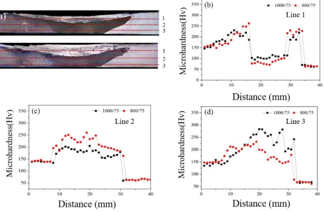
The material flow in the FSW joint between mild steel and aluminum was analyzed for both FSW parameter arrangements, 800 rpm - 75mm/min and 1000 rpm - 75 mm/min, applying a differential etching contrast method and OM, as presented in Figs. 2.6 and 2.7. The bright and dark zones correspond to the aluminum alloy and the mild steel respectively inside the figures.
For the FSW parameter combinations, the OM of the cross-sections reveals that the shoulder influenced area (SIF) is limited to the top part of the SZ. In contrast, the pin controlled the bottom part of the SZ (the pin-influenced area: PIF). In the SZ, the material flow occurred along the horizontal and vertical paths, as indicated by the blue arrows. Material flow in the SIF suggests the transmission of aluminum alloy as of the retreating side towards the advancing side alongside the horizontal path. Inside the PIF, the material movement is nearly the contrary. The steel as of the advancing side was extruded and penetrated the aluminum alloy in the retreating side, demonstrating an elongated band structure in the bottom part of the SZ.
26
Figure 2.8 (a) Material movement path and weld cross-section for 800/75 combination of parameters (b),(c)& (d) are magnified zones in advancing, central and retreating side as marked
in the weld cross section
Figure 2.9 (a) Material flow path and weld cross-section for 1000/75 combination of parameters (b), (c) & (d) are magnified zones in advancing, central and retreating sides is marked in the
weld cross-section
27
Figure 2.10 (a) SEM image of the midpoint of SIF with 1000 rpm / 75 mm/min and the consequences of EDS elemental scan of the region presented in (a): (b) aluminum and (c) iron;
(d) SEM image of the center of PIF with 1000 rpm /75 mm/min and the results of EDS elemental scan of the region shown in (d): (e) aluminum and (f) iron
28
In Figs. 2.6 (b)-(d) and Figs. 2.7 (b)-(d) intermixing of the steel and the aluminum alloy with the creation of lamellar patterns inside the SIF is clearly observed, as presented in the magnified views. The findings of the EDS elemental scan for the SIF and PIF with 1000 rpm / 75 mm/min (Fig. 4.5) validate the observation. This indicates that a certain amount of the steel extruded to the retreating side was again re-transferred to the advancing side. While the material flow paths for both FSW parameter combinations are generally related, the higher heat input by the parameter sequence with 1000 rpm spontaneously plasticizes the materials to a higher degree.
This causes, a greater volume of aluminum alloy transferring from the retreating side and a wider SIF for the parameter combination with 1000 rpm was generated inside the SZ.
2.3.3. Optical microscopy
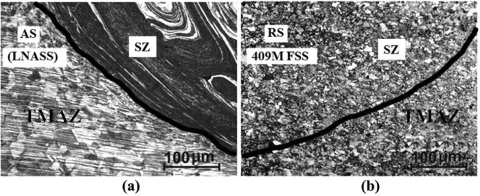
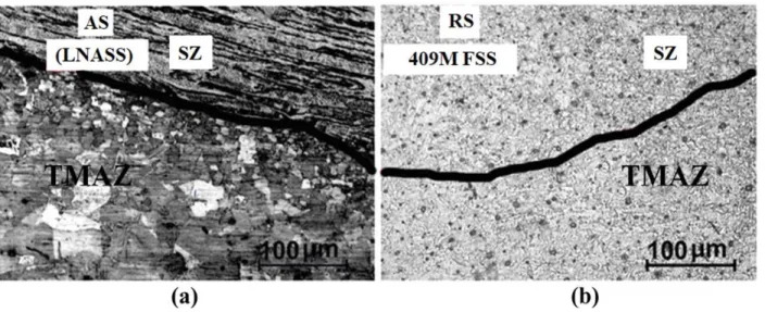
The optical micrographs of the stir zone and thermomechanically affected zone (TMAZ) were noticed for the 1000/50 and 1500/50 combinations, as displayed in Figs. 2.11 and 2.12.
Very fine equiaxed ferrite grains with austenite were observed in the upper region of the stir zone in the FSS side (Figs. 2.11 (b) and 2.12 (b)). The TMAZ/stir zone border in the advancing side (Figs. 2.11 (a) and 2.12 (a)) showed a semi-elliptical layered mixed mode of patterns, which mainly consisted of ferrite and austenite, likely with some percentage of martensite for most of the cases. It is fascinating to note that a better degree of grain refinement was noticed in the FSS side stir zone for all joining situations than that observed on the LNASS side.
.
29
Figure 2.11 SZ and TMAZ of 1000/50 combination of parameter (a) ASS and (b) FSS side
Figure 2.12 SZ and TMAZ of 1500/50 combination of parameter (a) ASS and (b) FSS side
30 2.3.4. EBSD assessment
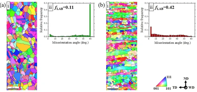
EBSD study was carried out in case of 1000/50 and 1500/50 parameter groupings for better understanding the dynamic recrystallization and phase transformation behavior. Inverse pole figure maps of the base LNASS and the base 409M FSS perpendicular to the welding direction (WD) are shown in Figs. 2.13 (a) and (b). In the LNASS, the misorientation distribution in Fig. 2.13 (a) (ii) reveals that about 48% of the high-angle boundaries (HABs) display the first-order twin coincidence-site lattice (CSL) orientation of Σ3 order . The amount of low angle boundaries (fLABs) with misorientation angles between 2o and 15o was very less in the LNASS (11%), while the 409M FSS in Fig. 2.13 (b) (ii) included a substantial quantity of fLABs
(42%). LNASS and the 409M FSS average grain sizes of were 37 and 10 μm, respectively.
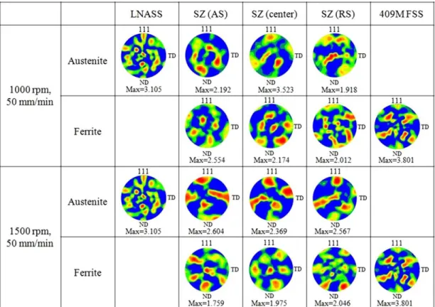
EBSD data related to the advancing side and the retreating side of the stir zone and the center of the stir zone, indicated SZ_AS, SZ_C, and SZ_RS, respectively, are displayed for the 1000/50 and 1500/50 blends in the form of phase maps perpendicular to WD in Fig. 2.14 Hybrid structures of ferrite and austenite were clearly observed for both 1000/ 50 and 1500/50 combinations in all three different regions, SZ-AS, SZ-C, and SZ-RS. {111} pole figures of the austenite and ferrite at SZ-AS, SZ-C, and SZ-RS are presented in Fig. 2.15 with individuals of the base LNASS and 409M FSS. The base LNASS has a stronger {111} <110> orientation while the base 409M FSS has a strong {110} <111> orientation. {h k l} is marked as the crystallographic plane normal to WD, and <u v w> is denoted to be a crystallographic direction parallel to WD. The texture components in SZ-AS, SZ-CN, and SZ-RS are distinct from those of the base metals for mutually austenite and ferrite phases. The various textures indicate that the materials underwent acute deformation during FSW [Field DP et al, Park SH et al, Sato YS et al].
The textures in SZ-AS, SZ-C, and SZ-RS are consistently possessing a strong simple shear
31
texture, particularly in ferrite for the 1500/50 combination. These textures initiated by the FSW process are quite related to the shear texture initiated by simple shear deformation of bcc materials. In the case of 1000/50 combination, fLAB of austenite in SZ (26%) is larger than that in LNASS (11%), and the grain size of austenite in SZ (2 μm) is considerably smaller as compared to LNASS (37 μm) as displayed in Figs. 2.16 (a) and (b). The fLAB of ferrite in SZ (47%) is somewhat larger than that in 409M FSS (42%), and the grain size of the ferrite in SZ (2 μm) is smaller than that in 409M FSS (10 μm), as shown in Figs. 2.16 (a) and b). LABs can be developed by dynamic recrystallization or recovery by rearrangement of deformation-induced space of lattice dislocations. The findings indicate that dynamic recrystallization and recovery happened as a result of the high deformation and heat generation throughout the FSW method for the 1000/50 combination conditions. In the case, 1500/50 parameter set, the fLAB of austenite and ferrite in SZ are bigger as compared to the LNASS and 409M FSS base metals, respectively; in addition grain sizes of the austenite and ferrite in SZ are meaningfully smaller than those of the LNASS and 409M FSS base metals, respectively, as displayed in Figs. 2.16 (a) and (b).
Therefore, dynamic recrystallization and recovery may have also occurred for the 1500/50 combination. In comparison with the 1500/50 and the 1000/50 combinations, the fLAB of austenite in SZ for the 1500/50 combination (51%) is almost two times higher than that for the 1000/50 combination (26%), as shown in Fig. 2.16 (a). Also, the grain size of austenite in SZ for the 1500/50 combination (13 μm) is more than six times larger than that for the 1000/50 combination (2 μm) (Fig. 2.16 (b)). In the case of ferrite, a higher fLAB of 51% with larger grain size (8 μm in SZ) is observed for the 1500/50 as compared to the 1000/50 combination (Figs.
2.16 (a) and (b)). From these results, it can be proposed that higher heat generation and more severe deformation at the higher tool rotational speed of 1500 rpm induced additional grain
32
growth with dynamic recrystallization and recovery. It is interesting to note that the degree of grain refinement in ferrite is remarkably higher than that of austenite, especially in the 1500/50 combination, as shown in Fig. 2.16 (b). This is probably because the stacking fault energy (SFE) of ferritic SS is larger than that of austenitic SS [Giossop BA et al, Bain EC et al]. It is well known that the partial dislocations become closer with increasing SFE and may readily recombine to facilitate cross-slip with the enhancement of dislocation cell formation [Giossop BA et al, Clark B et al]. As a result, ferritic SS, i.e., the 409M FSS in the present study, which has high SFE, may experience a strong continuous dynamic recrystallization, resulting in a very fine microstructure.
The pre-existing annealing twins within the LNASS rotated away from the ideal CSL orientation relationship (Fig. 2.11(c)) for both the 1000/50 and 1500/50 combinations, and the originally straight coherent twin boundaries were converted to general HABs. Such twin
33
Figure 2.13 (i) Inverse pole figure maps corresponding to welding path (WD) and (ii) misorientation-angle distributions of base metal: (a) LNASS and(b) 409M FSS, respectively
Figure 2.14 Phase maps (austenite in green, ferrite in red) corresponding to welding path (WD) of the (a) 1000/50 and (b) 1500/50 combinations; For the 1000/50 and 1500/50 combinations, the
center point of the observation areas was about 370 and 870 μm away from the welded surface, respectively
34
Figure 2.15 Pole figures of the 1000/50 and 1500/50 combinations at the regions marked as SZ (AS), SZ (RS) and SZ (center) in Fig. 2.14
Figure 2.16. (a) The fraction of low angle boundary (LAB), (b) grain size, and (c) the fraction of coincidence-site lattice (CSL) in austenite as a function of the distance from the weld center line
for the 1000/50 and 1500/50 combinations
35
boundary distortion seems to be a result of complex interactions of twin boundaries with slip dislocations [Mironov s et al]. Hardness is an indication of tensile strength. The microhardness plot across the weld in Fig. 2.17 suggests that the average hardness in SZ is comparatively higher than that of both base metals. The average hardness in SZ is the highest for the 1000/50 combination among the process parameter combinations selected in the present study. Note that fLAB in both austenite and ferrite in SZ is clearly higher for the 1500/50 combination than that of the 1000/50, which suggests that the material underwent a higher degree of dynamic recovery and recrystallization under the 1500/50 combination than under the 1000/50 combination. Also, the grain size of both austenite and ferrite in SZ for the 1500/50 combination is larger than that for the 1000/50 combination, as shown in Fig. 2.16 (b). Therefore, the hardness in SZ for the 1500/50 combination is expected to be lower than that for the 1000/50 combination, as shown in Fig. 2.17.
The hardness value of around 400 Hv clearly indicates the formation of a martensite and mixed-mode microstructure. This is validated by the results of tensile tests that all the joints failed from the softer FSS base metal (not shown). A few scattered points with very high hardness were observed in the TMAZ, and these are probably due to hardened precipitations.
The martensite increase in the 1000/50 combination may be explained by a higher cooling rate induced by a lower heat input in comparison with the 1500/50 combination.
36
Figure 2.17 Microhardness plot of the FSW joints
Figure 2.18 Vickers microhardness results of weld cross sections for 800/75 and 1000/75 parameters along line 1(b), 2 (c) & 3 (d)
37 2.4 Conclusion
Butt joints of LNASS and 409M FSS were successfully made by FSW. All the samples failed from the FSS base metal within the range of energy input selected in the present study.
EPMA mapping of the results of the 1000/50 and 1500/ 50 combinations reveals that the material movement pattern during FSW depends on the process parameter combination.
Dynamic recrystallization and recovery were observed in the FSW joints fabricated in the present study. Among the 1000/50 and 1500/50 combinations, additional grain growth in the stir zone was observed for the 1500/50 combinations due to the higher heat generation and more severe deformation compared to the lower tool rotational speed in the 1000/50 combination.
FSS with high SFE may affect the continuous dynamic recrystallization, resulting in a very fine microstructure.
Acknowledgement
This work was supported by the National Research Foundation of Korea (NRF) grant funded by the Ministry of Science, ICT & Future Planning (MSIP) (NO. NRF-2015R1A5A1037627). This research was also supported by the Ministry of Trade, Industry & Energy (MOTIE), Korea Institute for Advancement of Technology (KIAT) through the Encouragement Program for The Industries of Economic Cooperation Region.