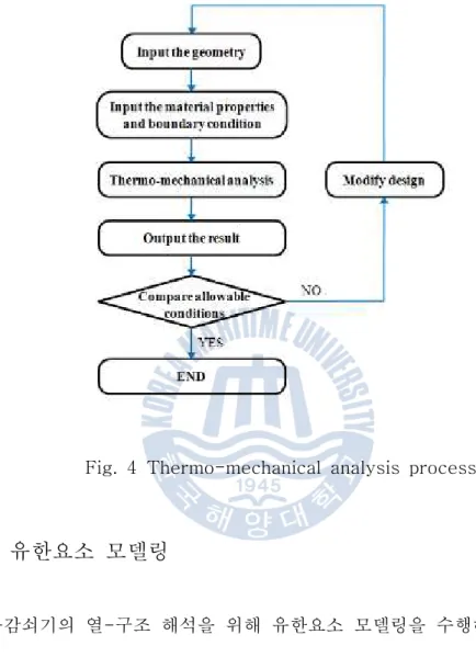
The purpose of structural analysis is to verify the life of the pulsation damper using thermomechanical analysis due to the operating pressure and thermal gradients during start-up and shutdown, during operation and with load changes. This study provides the sizing and voltage calculation for the pulsation damper using the applicable rules and calculation methods specified in ASME Section VIII, Division 2. The first step of the analysis is to determine the internal temperature distribution as a function of time for all operating modes and the Internal stresses were calculated for the critical temperature distributions at operating pressure.
The integrity of the pulsation damper is verified, the estimated fatigue application factors do not exceed 1.0. The critical fatigue areas of the pulsation suppressor are the junction of the shell, nozzle and backing plate. The application factors are the sum of the individual application factors and shall not exceed 1.0 and ASME Section VIII Section 2 Safety.

연구 배경
이로 인해 사용기간과 함께 수명에 대한 문제가 제기되고 있다. 이러한 피로 현상은 안전성과 신뢰성에 결정적인 영향을 미치며, 이로 인한 대규모 사고는 많은 인명 피해와 경제적 손실로 이어지기 때문에 피로 강도 평가를 통해 피로 손상 정도와 수명을 정확하게 예측하는 것이 필요합니다. 앞서 언급한 최대전단응력 이론과 최대변형에너지 이론을 비교해보면, 최대전단응력 이론은 재료의 실험값과 비교하여 차이를 보이기 때문에 최대전단응력 이론을 바탕으로 한 설계식을 이용하여 정확한 응력분포 및 수명평가를 계산한다. 전단응력 이론은 결코 쉽지 않습니다.
정확한 응력 분포와 수명 예측은 곧 경쟁력 있는 구조를 만들 수 있기 때문에 신축 발전소에 대한 대부분의 압력 용기 설계 표준은 이러한 변화를 반영합니다. 따라서 ASME 코드는 압력 용기에 대한 구조 분석 및 수명 평가 방법을 제공합니다. 이는 섹션 VIII 부문 2의 파트 5로 별도로 제시됩니다.
연구 동향
또한, 구조적 파괴는 응력집중 및 피로발생과 밀접한 관련이 있기 때문에 최근에는 정확한 피로수명을 추정하기 위한 Division 2, Part 5에 대한 연구가 더욱 활발해지고 있다. 압력용기 설계에 관한 기존 연구에는 보수적인 설계기준을 적용한 2007년 이전 ASME 코드를 기반으로 정립된 구조, 보강, 기계적 성능, 국부적인 노즐 응력 해석 등에 관한 많은 논문이 포함되어 있으나, 최대 변형에너지 이론 연구는 배포 후 스트레스 및 피로 분석은 여전히 미미합니다. 따라서 2장에서는 글로벌 시장에서 경쟁력 있고 컴팩트한 압력용기를 설계하기 위해 더 많은 연구가 필요하다.
ASME Section VIII, Division 2 Part 5의 피로평가 절차에 따라 강도해석을 수행하고, 그 결과를 이용하여 다양한 하중조건에서의 해석결과를 비교, 수정하여 세부설계프로세스를 표준화하였다. 따라서 본 논문의 목적은 2007년 이후에 발표된 ASME 섹션 VIII Division 2의 이론적 배경을 이해하고 이를 이 코드를 구현하는 압력 용기 설계 프로젝트에 활용하는 것입니다.
탄성 유한요소해석의 이론적 배경
이 식에서 는 Young's modulus, Poisson's ratio, 평균선형팽창 등의 상수이므로 어느 지점에서 변형률을 찾으면 그 지점의 응력을 계산할 수 있다.
압력용기 구조해석 방법
- 강도이론
- 구조해석 적용하중
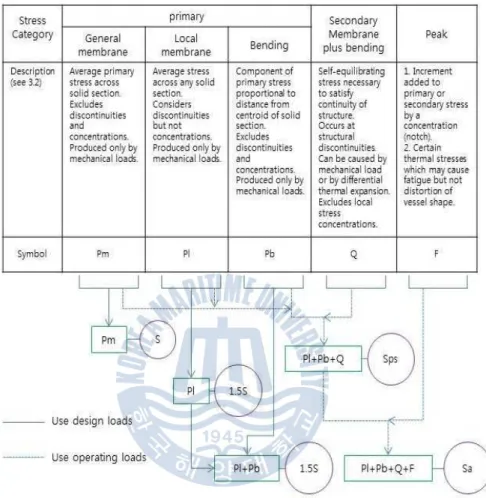
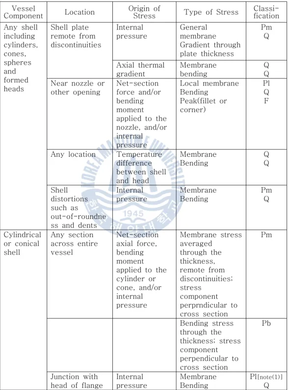
- 응력범주
- 일차응력
- 국부일차막응력
- 일차굽힘응력
- 이차응력
- 피크응력
- 응력평가
- 설계조건의 응력평가
- 운전조건의 응력평가
- 피로평가 절차
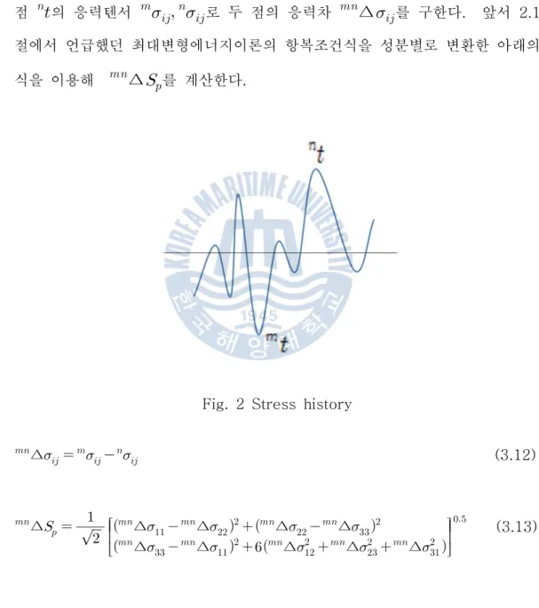
- 교번응력강도의 계산
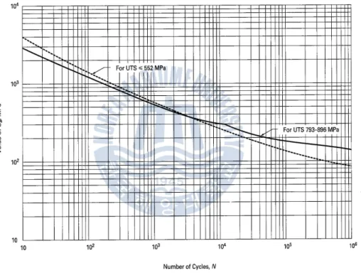
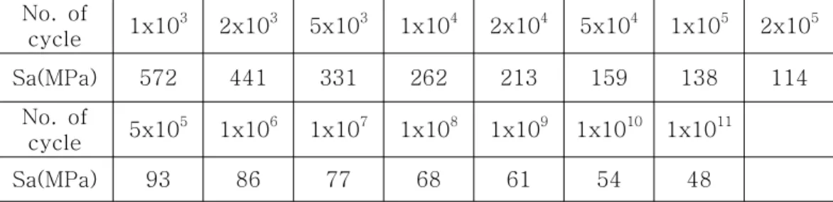
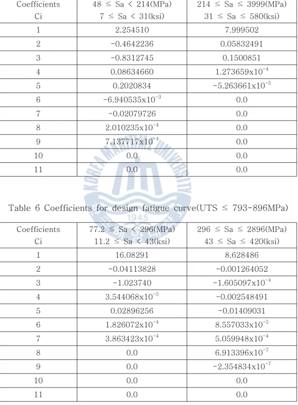
- 설계피로곡선
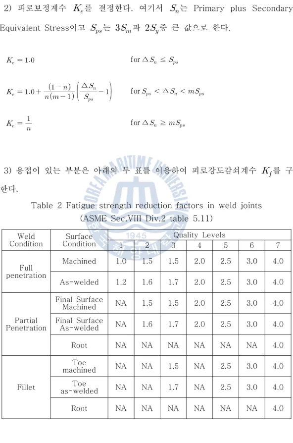
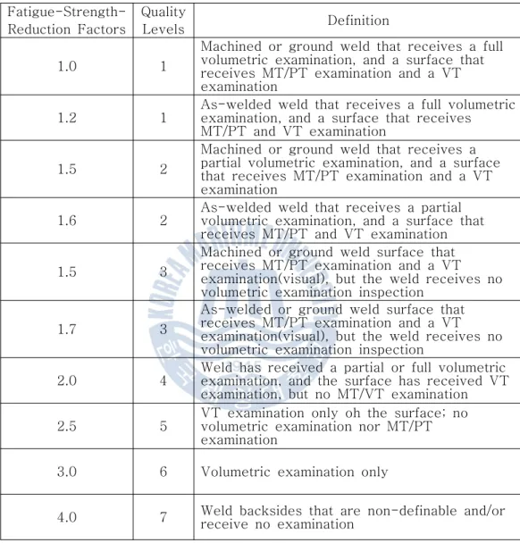
- 피로사용계수
- 누적피로손상 검토
따라서 1차 응력의 한계는 소성 변형을 방지하는 것입니다. 열 응력은 1차 응력으로 분류되지 않습니다. 국부적인 1차 막 응력은 압력이나 기타 기계적 하중으로 인해 막 응력이 발생하는 곳과 하나의 불연속점에서 다른 불연속점으로 하중 전달이 발생할 때 과도한 변형이 발생하는 곳에서 발생합니다.
2차응력이란 구조물의 자체구속이나 인접부분의 구속에 의해 발생하는 수직응력이나 전단응력을 말한다. 최대 응력의 기본 특성은 큰 변형을 일으키지 않지만 피로 균열이나 취성 파괴의 잠재적 원인이 된다는 것입니다. 일반적으로 최대 응력 계산은 반복 하중 조건에만 필요합니다.
응력등급은 작용하중이 설계조건인지, 운전조건인지에 따라 다르게 적용되며, Fig. 압력 용기 내에서는 다양한 하중 조건에 따라 여러 반복 응력이 발생합니다.
맥동감쇠기의 구조해석
유한요소 모델링
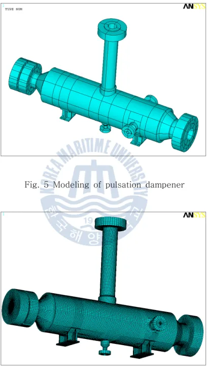
맥동댐퍼의 열구조해석을 위해 유한요소모델링을 수행하였다. 본 연구에서는 해석 프로그램으로 상용 코드인 ANSYS 11.0을 사용하였다. 이를 그림 5에 나타내었으며, 해석에 적용된 유한요소모델은 그림 5에 나타내었다.
해석에 사용된 솔리드 모델은 8-노드 솔리드 요소(열 솔리드 70, 구조 솔리드 185)를 사용했습니다.
해석조건
열-강도해석
- 열해석
- 설계조건시 강도해석
- 운전조건시 강도해석
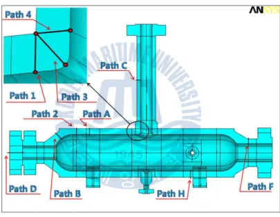
설계조건에서의 응력을 평가하기 위해 SCL(Stress Classification Line)을 그렸고, 절단면은 Fig. 노즐 하중과 설계 압력으로 인해 절단 표면에 발생하는 전체 응력 분포가 그림 1에 나와 있습니다. 작동 조건 중 응력을 평가하기 위해 SCL을 작성했으며 절단 표면은 그림 1에 나와 있습니다.
다이 하중, 중량, 온도 구배 및 작동 압력으로 인해 이 절단 표면에서 발생하는 전체 응력 분포가 그림 1에 나와 있습니다. 2, 작동 조건은 A와 B로 구분됩니다.
피로해석
- 운전조건
- 피로해석 결과 및 평가
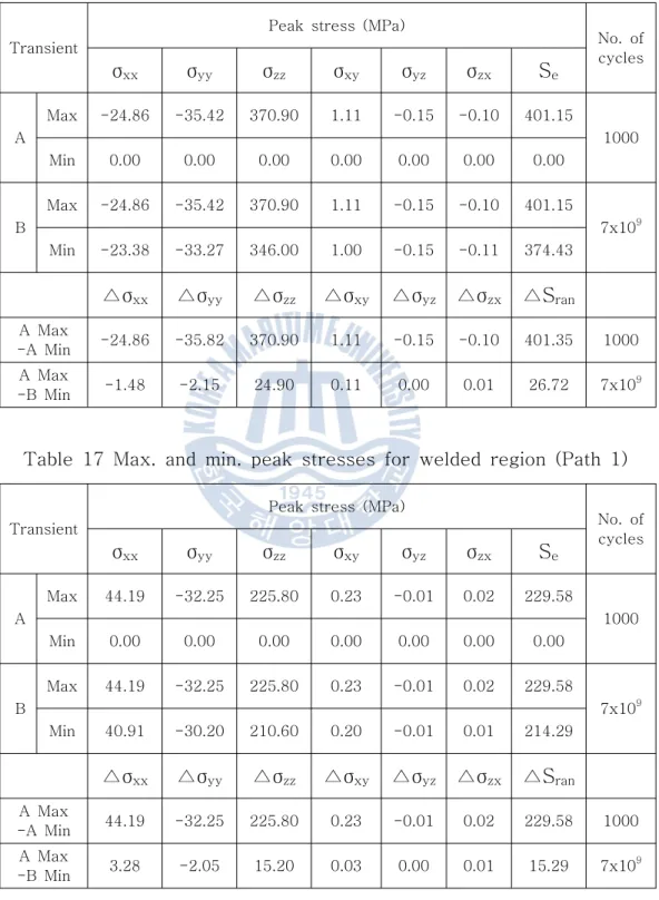
ASME Section VIII Section 2 Part 5에 제시된 방법을 이용하여 피로평가를 위한 피로이용계수(U)를 구하기 위해 ANSYS로 강도해석을 한 후 각 영역의 최대응력성분으로 를 사용한다. .
결론
5] Kalnins, A. og Updike, D.P., "Limit pressures of Cylindrical and Spherical Shells", Transactions of the ASME, Vol. 12] Zick, L.P., "Stresses in large Horizontal Cylindrical Pressure Vessels on Two Saddle Support", Pressure Vessel and Piping Design, Collected Papers 1927-1959.
Linearized Stresses for Design Condition
Linearized Stresses for Operating Condition A
Linearized Stresses for Operating Condition B