Then, the dimensions of the initial blank for the heading process were obtained by the law of constant volume. Then, the dimensions of the initial blank for the heading process were obtained using the volume-constancy law. Finally, the shank of the Al6061 alloy bolts is produced by the thread rolling process.
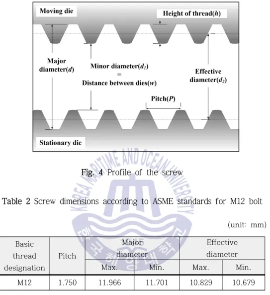
In general, the starting diameter for thread rolling is determined based on the effective diameter of the screw. The smaller the distance between the thread roll dies, the better the formability of the screw threads. To do this, information is required about the final shape of the bolt head and the initial diameter for the heading process.
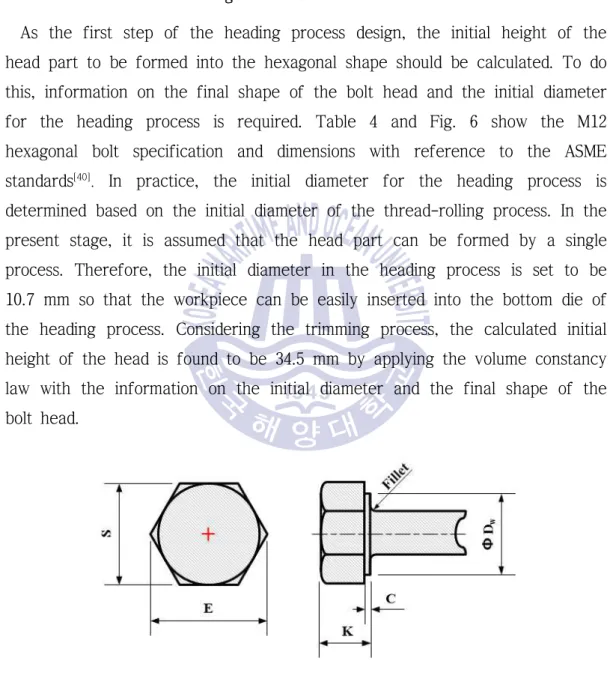
In practice, the initial diameter for the heading process is determined based on the initial diameter of the thread rolling process.

Taguchi method
Regardless of the quality attribute category, a larger SN ratio corresponds to better quality attributes. Therefore, the optimal level of the process parameters is the level with the largest SN ratio. Depending on the SN ratio, the optimal process conditions are selected, while the interaction between the process parameters is determined using the variance analysis.
A is at level i, mA is the number of replicate trials for A, TSN is the sum of SN ratios, DOFA is the degree of freedom of each parameter, VA.
Parameter design for the Taguchi method
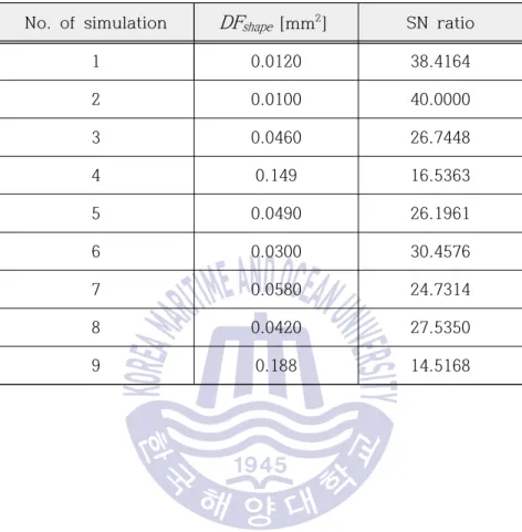
The BR of the punch and the stop distance between the punch and the lower die were determined by referring to previous research results[14,15]. To investigate the effects of the design parameters on the shear surface quality and shear load, two objective functions, i.e. shape defects (DFshape) and peak shear load (Loadpeak), specified as in Fig. Considering the influence on shear surface quality, weights of shape defects were determined as follows: wR = 0.2, wU = 0.3 and wB = 0.5.
21(b)), it is observed that multiple sets of shear and fracture occur during bolt shearing. Therefore, the peak shear load is generated at the end of the first cutting stage. The purpose of this research was to minimize the DF shape and Loadpeak in the trimming process.
Therefore, the signal-to-noise ratio (SN) was calculated using the smaller-better feature loss function with Eq. In the same way as the tensioning process, the Cockcroft & Latham criterion was adopted to investigate the fracture phenomena during the trimming process because it is easy to use and relatively accurate for the screw trimming process [15,47].
Conditions of FE-analysis in trimming process
Results of FE-analysis in trimming process
26 illustrates the distribution of damage or hydrostatic stress on the sheared plane during the trimming process. This may be due to the compressive hydrostatic stress acting on the shear zone between the punch and the workpiece. In addition, as in the previous study [15], the ultimate shear occurred with the formation of a crack at the A-A' section at a certain angle during the 2nd sequence due to the pinout.
Because the cross-sectional profile varies according to the critical value of damage in the analysis of the reduction process, it is very important to obtain the correct material properties and critical values of damage during each experiment. The cut plane profile and FE analysis results of the optimized process are shown in Fig. As a result, the sound shear surface and the minimum shear load are obtained, compared with the FE analysis results shown in the orthogonal array table.
28, the overturning occurred due to punching into the top of the bolt head. In general, the roll during the sheet cutting process is generated towards the direction of the punch due to the bending moment. However, due to the reaction force from the bottom, the material near the edge of the blade at the top of the head swells as much as the punch penetration volume in the bolt cutting process.
FE-analysis of thread-rolling process
Conditions of FE-analysis in thread-rolling process
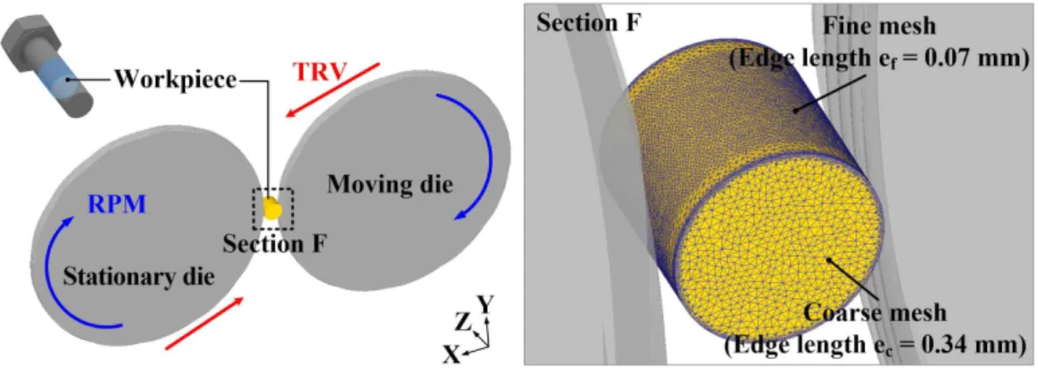
Based on the DOE using the Taguchi method, the FE analysis for the thread rolling process was performed using the DEFORM-3D software. According to the previous study[23], three-dimensional (3D) FE analysis is necessary to consider the effects of the groove orientation and the movement of the workpiece. The TRV is applied in the directions of the moving die and the stationary die to indent the workpiece.
To prevent the workpiece from escaping the dies, the central axis of the workpiece is fixed, allowing only rotation. Therefore, the friction factor (m) is set to 0.9, which is almost a dry friction condition, to prevent sliding between the dies and the workpiece [27]. 31 shows a 3D FE-model of the thread rolling process or the stress-strain curve of Al6061-T6.
Results of FE-analysis in thread-rolling process
However, as noted above, the results of simulations 6 and 7 were different from this tendency. In the analysis result of the larger TPR (Case A), the material and the dies are in contact in a wider area compared to the case B. 35 there is a significant difference in the radial velocity distribution of the material in the deformation area during the Process.
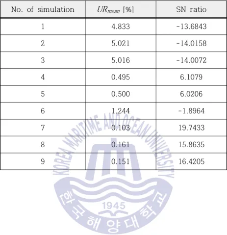
The velocity field of case B in the deformation zone with a relatively smaller value of TPR shows a higher average value than that of the analysis result for case A. This indicates that a smoother material flow occurs during the process, resulting in a sound filling of the material. Therefore, it can be seen that the lower the value of the TPR is set, the lower are the underfill ratio and forming load that can be achieved in the thread rolling process, which involves progressive forming through the rotation and transfer motion through rolling dies.
35 Comparison of the radial velocity distribution of the material in the deformation zone during the process (PD = 1.0 mm). It is also important that the yarns are fully formed so that the dimensions of the formed yarns meet the standard requirements. By applying the optimal process conditions in the FE analysis, the lowest thread torque load (8520 N) and the smallest underfill level (0.103%) were achieved compared to the results of the FE analysis using the orthogonal.
37 shows the effective stress distribution in the cross section of the deformed thread when the thread rolling process is completed. The stress is increasing towards the tip of the thread and shows a maximum effective stress of 4.77 at the tip and a minimum effective stress of 3.95 at the root. 36 Thread profile and effective stress distribution according to the number of revolutions of the thread turning process.
Experiment for manufacturing Al6061 alloy bolts
Experimental results
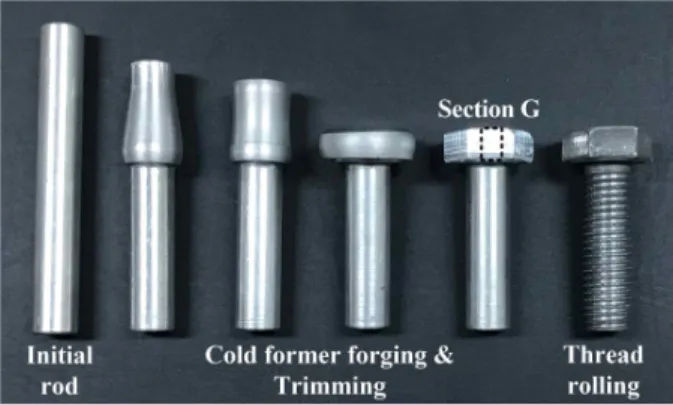
39 shows the shape of the bolt produced from Al6061 alloy at each stage of the integrated forming process. First, the application of process constraints to prevent cracks and bends in the head process, as well as the design of the preform taking into account metal flow, resulting in the sound shape of the bolt head, were verified. 15(b) ) showed no defects, and the shear profile of the cut bolt head is in good agreement with that obtained from the FE analysis, as presented in Fig.
Thus, it was proved that FE analysis based on the ductile fracture criterion was effective. 41 and Table 20, the dimension of the deformed wire part is very similar to the design shape. As a result, the design method for the integrated forming process of aluminum alloy bolts resulted in the successful product shape without any defect and the highest dimensional accuracy.
Conclusions
Investigating the rolling properties of titanium microscrew threads in relation to the design parameters of the die. Two-dimensional and three-dimensional finite element models of external thread rolling, Proceedings of the Institute of Mechanical Engineers, Part B: Journal of Engineering Manufacture, 216(4), pp.507-517. A parametric study of process parameters in external thread rolling, Journal of Materials Processing Technology p.341-349.
Characteristic evaluation of process parameters for improving lamination accuracy in lead screw, Korean Society of Precision Engineering Annual Fall Conference, pp.312-315. Determining the optimal gap diameter for high precision spindle screw, Transaction of Materials Processing, 11(8), pp.170-175. Numerical analysis and experimental study of thread turning process for micro-sized screws – Part 2: Application to an 800μm diameter microscrew, Transaction of Materials Processing, 21(3), pp.179-185.
Lead screw process design by thread rolling analysis, Annuals Spring Conference of The Korean Society of Mechanical Engineers, pp.1312-1316. Defect detection in thread rolling processes – Experimental investigation and numerical investigation of drive parameters, International Journal of Machine Tools and Manufacturing, 129, pp.27-36. Design of a thread rolling process for manufacturing Al6061-T6 alloy bolts using FE analysis and the Taguchi method, Journal of the Korean Society of Marine Engineering, 42(6), pp.443-450.
먼저 부족한 저를 학생으로 받아주시고, 따뜻한 관심과 세심한 지도로 참된 가르침을 베풀어 주신 이경훈 교수님께 머리 숙여 감사의 말씀을 드립니다. 또한, 고민과 선택의 갈림길마다 깊은 통찰력으로 지도해주신 김명환 교수님께도 진심으로 감사의 말씀을 전하고 싶습니다. 아울러, 학부 시절부터 늘 따뜻한 관심을 보여주신 조권회 교수님, 늘 아낌없는 격려와 도움을 주신 오철 교수님, 최재혁 교수님, 이 교수님께 감사의 말씀을 전하고 싶습니다. 고민이 있을 때마다 제 이야기를 들어주시고 조언을 해주신 원주님.