Introduction
Latency on Networks
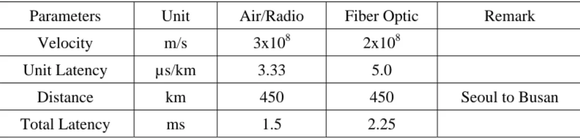
Total latency is the latency through optical cable of 2.25 ms plus the latency through network repeater of 2.25 ms, resulting in 4.5 ms total latency. Note that if the delay of fiber optic link network equipment is taken into account every 20 ~ 40 km in the road, the difference will be increased even more. If one considers the latency of all network nodes together, it will exceed a few tenths of milliseconds.
Therefore, fiber optic cable is no longer a good solution for an advanced delay-sensitive network or a speed-critical system. If one can reduce the latency of a device itself, the radio link will be faster than such a conventional fiber optic link. This is why a fiber-optic cable is used to a limited extent in such a time-sensitive financial network, but specially designed wireless radio is used to reduce latency in high-frequency trading (HFT).
E-band Wide-band Radiolink
For lower microwave frequencies up to about 30 GHz, atmospheric attenuation is relatively low at 0.2 dB per kilometer or less. It is the relatively low atmospheric attenuation window between 70 GHz and 100 GHz, which makes E-band frequencies attractive for higher capacity point-to-point fixed wireless transmission. These applications are all available in industry, universities, businesses, government agencies and hospitals with higher bandwidth needs.
The upcoming problem was securing the necessary bandwidth (BW) of 2.5 GHz (actually 2.2 GHz in the works) for 1.25 Gbps transmission with ASK. There are no such permitted wide frequency bands in the ISM band in 2.4 GHz, 5.8 GHz, 24 GHz or any other microwave frequency range. In Chapter IV, the future work on a CMOS approach will be briefly described as a preliminary attempt to reduce costs, finally followed by the completion of this work.
Low Latency E-band Radiolink Design
Proposed E-band Radiolink
- Introduction to Low Latency Radiolink
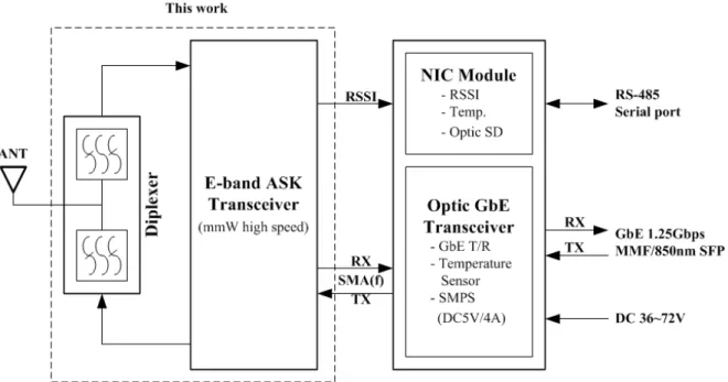
- Scheme of Proposed E-band Transceiver
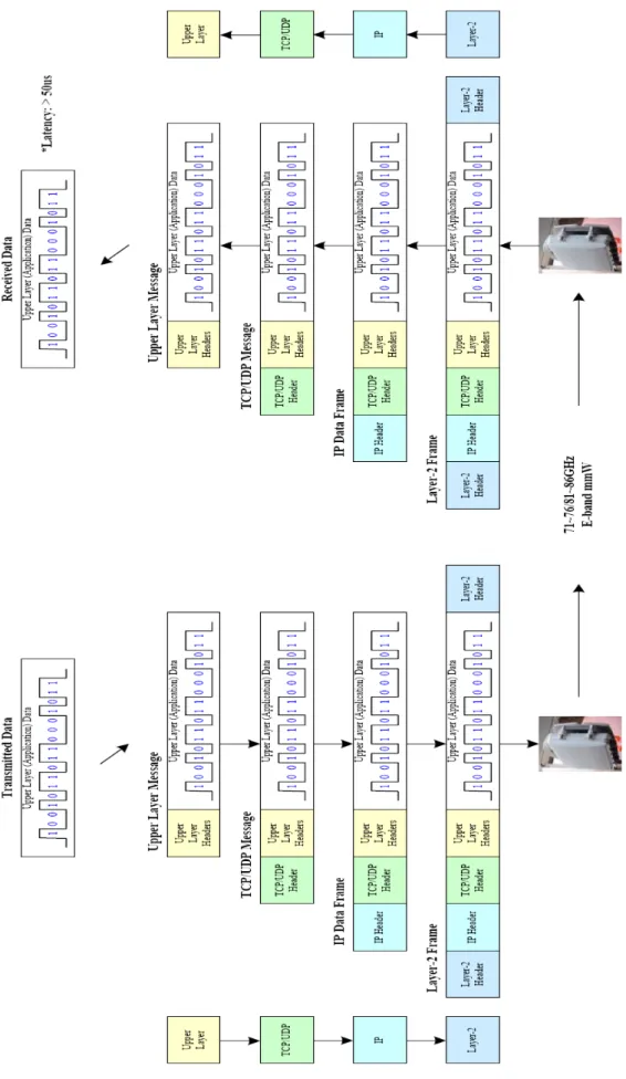
Rather, Figure 2.2 shows the schematic of the proposed ultra low latency Layer-1 radio link. By not adding or removing any IP protocol headers, the delivery of the signal is very fast without performing any signal processing. It can therefore achieve an ultra low latency of only a few tenths of a nano-second.
In conclusion, it does not work with Layer-2 equipment to guarantee low latency due to the delay. Heavy rain Potential OK NO Potential Potential Dust/Smoke OK OK NO OK OK Frequency Recycle. In this work, E-band high-speed mmW ASK transceiver and wideband E-band diplexer are designed for the ultra-low latency with ultra-wide bandwidth of 1.25 Gbps transmission.
Previous Work on Direct Conversion ASK Transceiver
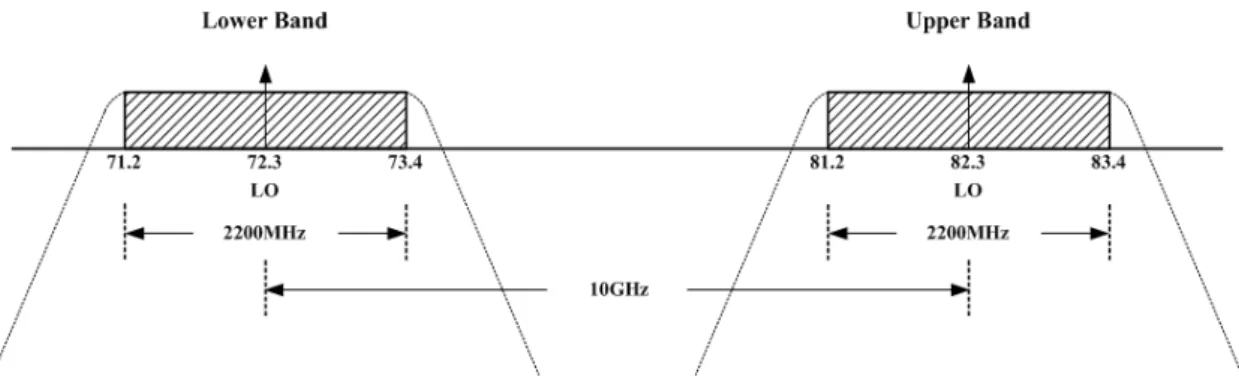
- Frequency plan for E-band Radiolink
- System Budget
- Design Review on Previous Work
- Measurement Result
- Challenging Issues on Direct Conversion
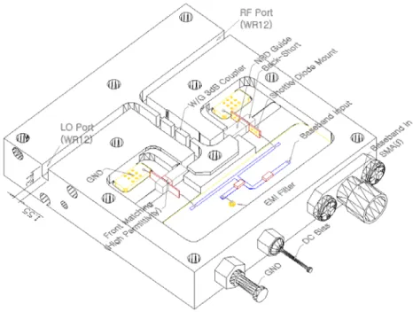
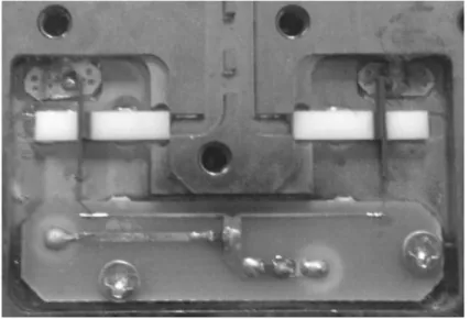
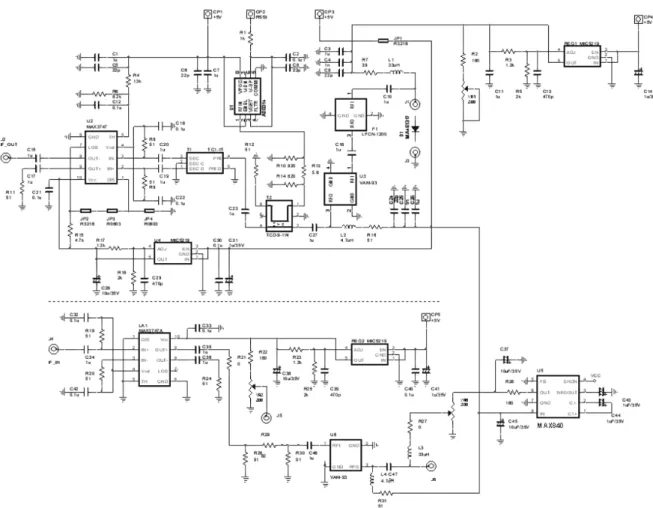
To transmit the capacity of 1.25 Gbps data rate using ASK, the required BW is theoretically 2.5 GHz. Therefore, building broadband characteristics greater than the required 2.2 GHz was the biggest challenge in this work. The LO input signal is switched through the baseband input and the ASK modulated output is pulled out using a waveguide coupler. a) (b) Figure 2.6 ASK modulator (a) Equivalent symbol (b) Implemented circuit.
Flatness in the GHz frequency band of interest was within +/-1 dB, which is good with the wide bandwidth characteristic of 2.2 GHz. Since the main problem was to establish wide bandwidth over DC up to 1.1 GHz, all parts were carefully selected to provide sufficient wide bandwidth characteristics. According to the measurement result, the dynamic range was from -65 dBm to -30 dBm, which was sufficient to cover the sensitivity of the designed ASK demodulator with a bandwidth of 1.1 GHz.
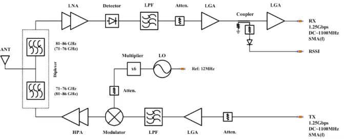
Proposed Heterodyne mmW ASK Transceiver
- Frequency Plan for E-band Radiolink
- Wideband ASK Modulator
- W/G-to-Microstrip Transition
- Mounting & Bonding Techniques for MMIC
- Design of mmW TX Front-End
- Design of mmW RX Front-End
- Design of PLO
- Implementation of Wide-Band IF & Baseband Section
- AGC Circuit for Temperature Compensation
- Implementation of E-band Transceiver
- Guide Wavelength of WR12
- Waveguide Inductive Iris Filter
- Extraction of K-Inverter Parameter
- Design of Inductive Iris Filter
- Design of T-junction
- Simulation Result
- Measurement Result
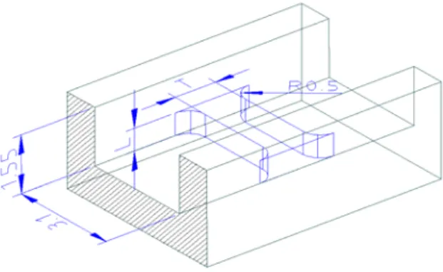
By converting the calculated matrix ABCD of (2.4.1) to parameter S, the insertion loss and return loss can be calculated. The metal iris width T of 1.0 mm and R of 0.5 mm were chosen to have optimal inverter slope K consistent with height L. The designed inverter K and the height of each iris stage are shown in Table 2.9 and Table 2.10.
Design factors are width W and length D with round radius of 0.5 mm considering the end mill. In the case of two bandpass filters connected to build diplexers by using T connection, as shown in Figure 2.61, the signal spectra of the F1 frequency range from the input port pass easily through the F1 filter, but are reflected at F2 and return to F1 or entrance gate again. By matching the link length in this way, the required wide band of 2.2 GHz diplexers was successfully achieved.
According to the simulation results, it shows good matching in both bands as expected with a return loss of less than -27dB. As you can see, the insertion loss is less than 1.0dB and the return loss is less than -15dB. The measured insertion loss is less than 2.2 dB and the return loss is less than -15 dB.
Measurement Results
- Data Rate & Dynamic Range
- Latency
High-speed 1.25 Gb/s GbE signals modulated on each LO carrier are transferred to the receiver and demodulated as described in Section 2.3. The test signal from the DQA with 1.25 Gbps Ethernet is connected to the designed transceiver-A and is detected at the other end of the transceiver-B. Figure 2.78 Measurement setup with a temperature chamber. At a room temperature of 25 degrees, the sensitivity is measured to be -45 dBm for unit A and -46 dBm for unit B. Table 2.13 Dynamic range test result.
Dynamic range is generally defined as the ratio or difference in dB of the peak input level that. the system can transfer to the lowest input level at which the system provides adequate signal quality. Table 2.13 summarizes the dynamic range test result with BER 10-12 or error-free benchmarks. The noise figure is a measure of how much the SNR is reduced as the signal passes through the system.
For a cascade of stages, the total noise figure can be obtained in terms of NF and gain for each stage. The other path was loop supported through implemented E-band transceiver as round-trip and put in the same oscilloscope as CH2. Between two radio units, E-band variable attenuator was attached to properly attenuate the TX current.
The function of the optical interface board is to convert the signal between the electrical signal and the optical fiber signal with clock data recovery. The signal labeled CH1 is from the direct path and CH2 indicates the signal through the implemented E-band radio unit of the return path. The time difference is 38.2 ns, which is the round-trip delay of the radio unit.
Most commercial manufacturers provide more than 50 μs latency up to 350 μs in the case of Siklu..band and SIAE achieved a quite good latency of less than 5 μs, but this is still large compared to the 19.1 ns obtained in this work.
Field Test
- Link Budget
- Field Test
- Availability Analysis
- Interference Free Scenario
According to the link budget analysis, the estimated MDS level is approximately -46 dBm with the required SNR of 25 dB under BER 10-12 criteria. In order to have good line-of-sight (LOS), the test site was carefully selected, without any obstacles along the way. According to the estimated link budget, the field test was conducted at a distance of 4.1 km in Ulsan, South Korea.
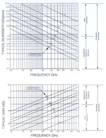
With the implemented parameters in this work, the link distance was estimated using the link budget calculation shown in Table 3.1 in accordance with the ITU-R recommendation. Due to the pencil beam characteristic of E-band frequency radiation, two radio units are deployed in open terrain with LOS. Even though the beam width of 3 dB is only 0.8 ~ 0.9 degrees, interference may occur due to the side lobes of the antenna beam pattern when two radio links are installed close to each other on the same tower.
If unit-A is installed horizontally at location 1, unit-B must be installed at location 2 with the same polarity. If unit-A is installed with vertical polarization, unit-B must be installed at the other location with the same polarity. . Case Location 1 Location 2 I AH: Unit-A Horizontal BH: Unit-B Horizontal II AV: Unit-A Vertical BV: Unit-B Vertical III BH: Unit-B Horizontal AH: Unit-A Horizontal IV BV: Unit-B Vertical AV: Unit-A vertical.
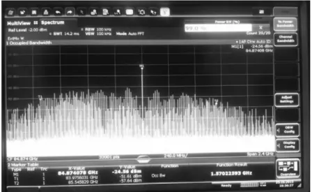
If two connections are to be installed in the same location, the possibility of interference must be considered. Then by placing one of the links close to the other, the separation was measured when errors occur at one of the links due to the interference. AH: Unit-A Horizontal BH: Unit-B Horizontal AV: Unit-A Vertical BV: Unit-B Vertical BH: Unit-B Horizontal AH: Unit-A Horizontal BV: Unit-B Vertical AV: Unit-A Vertical 72.375 GHz .
AH: Unit-A Horizontal BH: Unit-B Horizontal AV: Unit-A Vertical BV: Unit-B Vertical BH: Unit-B AH Horizontal: Unit-A BV Horizontal: Unit-B Vertical AV: Unit-A Vertical.
Future Work
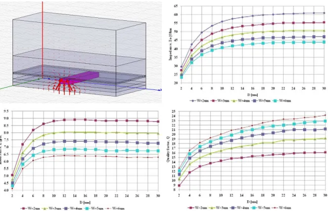
By changing the defined dimension of the line width W and the distance D from the wall (Figure 4.1), we determined the required dimension of the 50 Ω transmission line. A conjugate matching technique was used to match the impedance between the output of the first stage and the input of the next stage. The problem was to provide the required 2.5 GHz bandwidth (actually 2.2 GHz in the works) to transmit 1.25 Gbps with ASK.
By adopting the heterodyne topology, the construction burdens of an ultra-wideband ASK modulator in the 70/80 GHz millimeter wave range were eased. However, building the 1.25 Gbps ASK modulator in the IF stage presented another new challenge. Emulex Inc., 'Achieving Ultra-Low Latency for High Frequency Trading Applications', Cisco, http://www.emulex.com/resources, accessed March 2013.
LightPointe 2014, 'Millimeter Wave (MMW) Radio Broadcasting: An Application and Technology Primer', LightPointe, www.lightpointe.com. O3b Networks, 'What is network latency and why does it matter?', O3b Networks, http://www.o3bnetworks.com/media/40980/white%20paper_latency%20matters.pdf, accessed August 2012. Sub10 Systems, ' 70 /80 GHz Wireless Backhaul for Macro Cell Backhaul & Enterprise Connectivity', Liberator-E1000c, Sub10 Systems Limited, www.sub10systems.com.
Fujitsu Wireless, "Fujitsu Network BroadOne Series GX4000", Fujitsu Wireless Systems Limited, http://jp.fujitsu.com/group/fwl/. Sub10 Systems, 'Gigabit Full-Duplex në distanca deri në 4 km', Liberator-E1000e, Sub10 Systems Limited, www.sub10systems.com. Bui LQ, Ball D & Itoh T 1984, 'Broad-band Milimeter-Wave E-Plane Bandpass Filters', IEEE Trans., Vol.
Chinh HD, Sohrab E, Ali MN & Robert WB 2005, 'Millimeter-Wave CMOS Design', IEEE Journal of Solid-State Circuits, Vol 40, Nr.
Conclusion

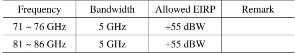
![Table 1.2 shows E-band frequency allowance in USA [18] and the same regulation is allowed in most countries including South Korea [19] [20]](https://thumb-ap.123doks.com/thumbv2/123dokinfo/10537334.0/22.892.276.615.578.950/table-frequency-allowance-regulation-allowed-countries-including-south.webp)