Comparison of the frictional characteristics of aesthetic orthodontic brackets measured using a modified in vitro technique
Objective: The coefficients of friction (COFs) of aesthetic ceramic and stain- less steel brackets used in conjunction with stainless steel archwires were investigated using a modified linear tribometer and special computer software, and the effects of the bracket slot size (0.018 inches [in] or 0.022 in) and materials (ceramic or metal) on the COF were determined. Methods: Four types of ceramic (one with a stainless steel slot) and one conventional stainless steel bracket were tested with two types of archwire sizes: a 0.017 × 0.025-in wire in the 0.018-in slots and a 0.019 × 0.025-in wire in the 0.022-in slot brackets. For pairwise comparisons between the 0.018-in and 0.022-in slot sizes in the same bracket, an independent sample t-test was used. One-way and two-way analysis of variance (ANOVA) and Tukey’s post-hoc test at the 95% confidence level (α
= 0.05) were also used for statistical analyses. Results: There were significant differences between the 0.022-in and 0.018-in slot sizes for the same brand of bracket. ANOVA also showed that both slot size and bracket slot material had significant effects on COF values (p < 0.001). The ceramic bracket with a 0.022-in stainless steel slot showed the lowest mean COF (m = 0.18), followed by the conventional stainless steel bracket with a 0.022-in slot (m = 0.21). The monocrystalline alumina ceramic bracket with a 0.018-in slot had the highest COF (m = 0.85). Conclusions: Brackets with stainless steel slots exhibit lower COFs than ceramic slot brackets. All brackets show lower COFs as the slot size increases.
[Korean J Orthod 2015;45(1):29-37]
Key words: Brackets, Archwires, Coefficient of friction, Tribometer Nursel Arici
Berat Serdar Akdeniz Selim Arici
Department of Orthodontics, Faculty of Dentistry, Ondokuz Mayis University, Samsun, Turkey
Received March 14, 2014; Revised July 11, 2014; Accepted July 14, 2014.
Corresponding author: Nursel Arici.
Assistant Professor, Department of Orthodontics, Faculty of Dentistry, Ondokuz Mayis University, 55139, Atakum Samsun, Turkey.
Tel +90-506-8605901 e-mail [email protected]
© 2015 The Korean Association of Orthodontists.
The authors report no commercial, proprietary, or financial interest in the products or companies described in this article.
This is an Open Access article distributed under the terms of the Creative Commons Attribution Non-Commercial License (http://creativecommons.org/licenses/by-nc/3.0) which permits unrestricted non-commercial use, distribution, and reproduction in any medium, provided the original work is properly cited.
pISSN 2234-7518 • eISSN 2005-372X
http://dx.doi.org/10.4041/kjod.2015.45.1.29
INTRODUCTION
Orthodontic tooth movement is frequently carried out by bonding a bracket to the tooth surface and placing an archwire in the bracket slot. Under tension, this archwire applies a gentle force to the tooth that moves it in the desired direction. During this process, sliding friction is generated between the archwires and brackets as the wires guide the brackets during mesiodistal movement of an individual tooth or when archwires are passed through posterior crown attachments.
1The magnitude of the force applied to the teeth should be optimized to obtain the fastest possible tooth movement.
2For example, in some cases, forces less than or greater than this optimal value can cause tooth movement to slow or even stop completely. During orthodontic therapy, friction at the bracket slots and archwire contact areas can prevent the practitioner from obtaining these optimal force values, affecting both the treatment duration and the effects of therapy on the surrounding structures of the teeth.
3It was reported that in some situations, the effective force should be increased six fold to overcome frictional resistance.
4Thus, increased frictional resistance can require the orthodontist to use excessive force, which can result in anchorage loss, patient discomfort, and injury to tooth- supporting tissues during treatment.
5Understanding of the friction phenomenon is therefore essential for understanding what actually happens at the bracket/
archwire interface under many different conditions.
To date, several methods have been developed for the quantitative evaluation of friction in orthodontics. One accepted method for quantitative characterization of friction is to define a coefficient of friction (COF) at the bracket/archwire interface,
6-12which is defined as the proportionality constant between the frictional force and the applied load (that is, the normal force).
13In orthodontics, the sliding friction can be affected by various factors such as the bracket and wire materials, surface conditions of the archwires and the bracket slot, wire cross section, torque at the wire-bracket interface, type and force of ligation, inter-bracket distance, saliva, and different oral functions.
5Currently, there are three major groups of bracket materials: metal, plastic, and ceramic. Commonly used metal brackets are made of stainless steel and have been shown in many studies to have the most ideal frictional characteristics among the three materials. Ceramic brackets have come into widespread use because of their aesthetic characteristics.
However, studies have reported higher COFs for these brackets, along with greater frictional resistance, rougher surfaces, and a greater tendency to retard tooth movements compared to stainless steel brackets.
6,14Many researchers have shown increased frictional resistance,
especially with polycrystalline ceramic and plastic brackets.
15,16Therefore, aesthetic brackets with metal slots were developed to decrease the frictional forces and overcome these drawbacks of ceramic materials.
16Stainless steel archwires also show better results than beta-titanium or nickel-titanium archwires in terms of their frictional characteristics.
4,6Although more sensitive measurements could provide researchers with a better understanding of the problems that cause increased frictional forces, simple universal testing machines have generally been used to measure and compare the frictional forces generated by the brackets and archwires in most previous studies on this subject.
3,7,8,17,18In the field of orthodontics, investigations on friction have been roughly classified into four groups according to the type of friction test setup: (1) archwires sliding through contact flats, (2) archwires sliding through brackets parallel to the bracket slot, (3) archwires sliding through brackets with different second- and third-order angulations, and (4) brackets submitted to a force with a certain degree of tipping allowed.
19Our hypothesis was that testing the friction with a linear tribometer modified particularly for this subject would show no significant difference in the resistance to sliding of stainless steel archwires through 0.018-inches [in] and 0.022-in slots in aesthetic brackets. The tribometer and experimental test set-up used in this study were modified to measure an archwire sliding through a bracket, as in clinical applications, and the COF was chosen as the measure of the bracket/archwire interface friction. In particular, the tribometer was modified to allow the measurement arm to move in a linear direction, and a specially developed computer software program was used to measure and calculate the COF of the tested specimen. Although conventional circular-motion pin-on-disk tribometers are generally used to calculate the dynamic friction, the linear measurement technique used in this study can evaluate the time-dependent changes in the friction values, which are important in clinical practice. Therefore, the purposes of this in vitro study were to measure the COFs generated by aesthetic bracket/stainless steel archwire combinations with two different slot sizes using a modified linear tribometer and special computer software and to compare these COFs to those of conventional stainless steel metal brackets.
MATERIALS AND METHODS
The sample size in this study was calculated using a
significance level of 0.05 and a power of 90% to detect
meaningful differences among the mean COF values
of the groups. After a pilot study, the power analysis
(NCSS 2007 and PASS 2008 statistical software; NCSS, Kaysville, UT, USA) showed that nine samples from each group were required. To allow for any sample dropout, a sample size of ten was chosen for each group.
Four types of ceramic brackets were tested: one ceramic bracket with stainless steel slots (Clarity; 3M/
Unitek, Monrovia, CA, USA), one monocrystalline alumina ceramic bracket (Pure; Ortho Technology, Tampa, FL, USA), and two polycrystalline alumina ceramic brackets (Transcend, 3M/Unitek; InVu, TP Orthodontics, La Porte, IN, USA). A conventional
stainless steel bracket (Gemini, 3M/Unitek) was also tested as a control. The specifications of the brackets are listed in Table 1.
All of the brackets used in this study were maxillary premolar brackets. COF testing was performed with two types of stainless steel straight-length archwires: 0.017
× 0.025-in archwires for the 0.018-in slot brackets and 0.019 × 0.025-in archwires for the 0.022-in slot brackets (Table 1). One of the brackets (InVu) had only a 0.022-in slot. For each group, ten freshly prepared combinations of the archwire and bracket were tested.
Positioner
Weight (150 g)
Bracket holder Arch wire holder
Tightening screw
Tightening sphere
Metal cylinder
Bonded sphere Bracket
Arch wire
A B C
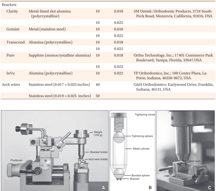
Figure 1. Modified CSM tribometer test equipment (A), schematic drawing of the bracket holder part (B), and close-up view of bracket (upper) and archwire (lower) holding parts (C).
Table 1. Descriptions and manufacturers of the materials used in this study
Material n Slot size (inch) Manufacturer
Brackets
Clarity Metal-lined slot alumina (polycrystalline)
10 0.018 3M Unitek; Orthodontic Products, 2724 South Peck Road, Monrovia, California, 91016, USA
10 0.022
Gemini Metal (stainless steel) 10 0.018
10 0.022
Transcend Alumina (polycrystalline) 10 0.018
10 0.022
Pure Sapphire (monocrystalline alumina) 10 0.018 Ortho Technology, Inc.; 17401 Commerce Park Boulevard, Tampa, Florida, 33647,USA
10 0.022
InVu Alumina (polycrystalline) 10 0.022 TP Orthodontics, Inc.; 100 Center Plaza, La Porte, Indiana, 46350-9672, USA
Arch wires Stainless steel (0.017 × 0.025 inches) 40 G&H Orthodontics; Earlywood Drive, Franklin, Indiana, 46131, USA
Stainless steel (0.019 × 0.025 inches) 50
Measurement technique
A standard CSM pin-on-disk tribometer (CSM Instruments, Peseux, Switzerland) was modified to allow linear reciprocating wear testing, as shown in Figure 1.
In particular, a specially adapted archwire holding block was mounted on frictionless bearings above the circular motor in such a way as to allow the archwire to move in a direction perpendicular to the bracket bearing load arm.
After degreasing of the brackets and archwires with acetone, the brackets were bonded on a metal sphere that was sandblasted and seated inside of the upper head of the tribometer. The bracket could be moved around this sphere before it was stabilized with a screw.
This process helped to eliminate the effects of excessive inclination values (binding) by allowing the bracket slot to move in three dimensions. A force of 150 g was loaded on the upper head, which could move up and down freely to simulate the effect of orthodontic ligatures on the friction.
6A straight-length archwire was seated in the middle of the slot with the help of 0.022 × 0.025-in and 0.018 × 0.025-in stainless steel guidance wires for the 0.022-in and 0.018-in slot brackets, respectively. These guidance wires were seated on the lower head before the tested archwire. The bracket was then positioned on the wire, and the final position stabilized with a screw.
After the bracket was stabilized, the guidance wire was dismantled. Then, the archwire to be tested was mounted in place and stabilized with two screw clamps.
The test was ready to begin when the bracket was approximated and the archwire was seated in the middle of the bracket slot. The bracket was moved on the stainless steel archwire at a speed of 17 mm/s (~1 mm/
min) for 10 mm to measure the dynamic friction. Special software was used to collect the data and calculate the COF for each bracket/archwire combination. Ten measurements were recorded every second during the sliding tests, and the mean frictional values from
approximately 6,000 readings were automatically calculated for each bracket/archwire combination.
All samples were tested under dry conditions at room temperature (24
oC). The tribometer was covered with a glass box to prevent outside noise from affecting the sensitive measurements during testing. Apart from the standard test parameters (frequency, contact pressure, and time) the environmental parameters (24
oC temperature and 50% relative humidity ) were also kept under control in a laboratory with an HVAC (heating, ventilation, and air conditioning) system.
The surface morphology of the tested bracket/archwire couples was examined under a stereo light microscope (SMZ 1500; Nikon, Tokyo, Japan) to evaluate the wear patterns of the material surfaces. From each group, selected samples were also photographed (Digital Sight DS-L1, Nikon) at 30× magnification.
Statistical analysis
The data were analyzed using a statistical software package program (SPSS, ver. 12.0; SPSS Inc., Chicago, IL, USA). Because the data were normally distributed in all groups according to the Shapiro-Wilk normality test, Student’s t-test for independent samples was used to compare the COFs for the 0.018-in and 0.022-in slot sizes in the same-brand brackets (except for the InVu brackets). In addition, to determine the effects of the slot size (0.018 in or 0.022 in) and bracket slot material (ceramic or stainless steel) on the COFs of the groups, one-way and two-way analysis of variance (ANOVA) was used. This test was followed by Tukey’s honestly significant difference (HSD) test for multiple comparison of means, ranked at p < 0.05, to determine differences among the different groups.
RESULTS
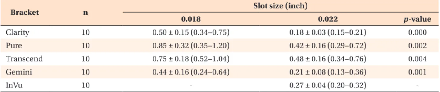
The means, standard deviations, and minimum and maximum values (range) of the COFs measured in vitro for the groups are listed in Table 2. The lowest mean
Table 2. Descriptive statistics and comparisons of the measured coefficients of friction (m)*
Bracket n Slot size (inch)
0.018 0.022 p-value
Clarity 10 0.50 ± 0.15 (0.34−0.75) 0.18 ± 0.03 (0.15−0.21) 0.000
Pure 10 0.85 ± 0.32 (0.35−1.20) 0.42 ± 0.16 (0.29−0.72) 0.002
Transcend 10 0.75 ± 0.18 (0.52−1.04) 0.48 ± 0.16 (0.34−0.76) 0.004
Gemini 10 0.44 ± 0.16 (0.24−0.64) 0.21 ± 0.08 (0.13−0.36) 0.001
InVu 10 - 0.27 ± 0.04 (0.20−0.32) -
Values are presented as mean ± standard deviation (minimum –maximum).
*For the 0.018-inches and 0.022-inches slot sizes with the same brand brackets obtained from independent t-tests.
Refer to Table 1 for the explanation about each product.
COF value (m = 0.18) was found for 0.022-in ceramic brackets with stainless steel slots (Clarity), followed by the stainless steel bracket (Gemini) groups (m = 0.21).
The mean COF values of all of the 0.018-in slot groups were nearly twofold greater than those of their 0.022-in slot counterparts (Figure 2). Pairwise comparisons with an independent sample t-test revealed that all of the 0.018-in slot bracket groups showed significantly higher COF values than their counterparts in the 0.022-in slot bracket groups (Table 2).
Since significant differences were found between the two slot sizes, the data for the 0.018-in and 0.022-in slot brackets were treated separately. The comparison between the groups for each slot size was made using
one-way ANOVA (Table 3), which showed significant differences among the 0.018-in slot bracket groups.
The grouping of these differences obtained from Tukey’s HSD multiple-range test indicated that Gemini brackets had significantly lower COFs than the Pure and Transcend brackets in the 0.018-in slot group, except for the ceramic brackets with stainless steel slots (Clarity).
In the 0.022-in slot group, Clarity brackets showed
Figure 2. Mean coefficient of friction (COF) values of the brackets tested.
Refer to Table 1 for the explanation about each product.
COF
Clarity Pure
Bracket
0.018 inches slot 0.022 inches slot
0.0 0.9 0.8 0.7 0.6 0.5 0.4 0.3 0.2 0.1
Transcend InVu Gemini
Table 3. Results of one-way ANOVA for the 0.018-in and 0.022-in slot size bracket groups
Bracket Slot size (inch)
0.018 p-value* 0.022 p-value*
Clarity 0.50 ± 0.15 A, B 0.18 ± 0.03 D
Pure 0.85 ± 0.32 C 0.42 ± 0.16 E
Transcend 0.75 ± 0.18 B, C 0.48 ± 0.16 E
Gemini 0.44 ± 0.16 A 0.21 ± 0.08 D
InVu 0.27 ± 0.04 D
Values are presented as mean ± standard deviation.
The number of each bracket = 10.
ANOVA, Analysis of variance.
*Different letters in the 0.018-inches [in] (A to C) and 0.022- in slot size bracket groups (D and E) indicate statistically significant differences (p < 0.05) between the brackets with the same slot size according to Tukey’s honestly significant difference post-hoc test.
Refer to Table 1 for the explanation about each product.
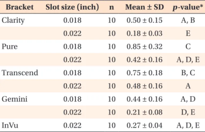
Table 4. Comparisons of the mean COF values for all bracket groups obtained from two-way ANOVA
Bracket Slot size (inch) n Mean ± SD p-value*
Clarity 0.018 10 0.50 ± 0.15 A, B
0.022 10 0.18 ± 0.03 E
Pure 0.018 10 0.85 ± 0.32 C
0.022 10 0.42 ± 0.16 A, D, E
Transcend 0.018 10 0.75 ± 0.18 B, C
0.022 10 0.48 ± 0.16 A
Gemini 0.018 10 0.44 ± 0.16 A, D
0.022 10 0.21 ± 0.08 D, E
InVu 0.022 10 0.27 ± 0.04 A, D, E
*Different letters in the 0.018-inches [in] (A to C) and 0.022- in slot size bracket groups (D and E) indicate statistically significant differences (p < 0.05) between the brackets with the same slot size according to Tukey’s honestly significant difference post-hoc test.
COF, Coefficient of friction; ANOVA, analysis of variance; SD, standard deviation.
Refer to Table 1 for the explanation about each product.
Figure 3. Profile plot showing no interaction between slot size (0.018 inches [in] and 0.022 in) and bracket material from the two-way analysis of variance. COF, Coefficient of friction; G, Gemini metal; C, Clarity metal- slot ceramic; I, InVu ceramic; P, Pure ceramic; T, Transcend ceramic brackets.
Refer to Table 1 for the explanation about each product.
Estimatedmarginalmeans(COF=)
G C T P I
Bracket
0.018-in 0.022-in 0.80
0.60
0.40
0.20
Slot
significantly lower COFs than the Transcend and Pure brackets. There were no significant differences among the Gemini, InVu, and Clarity brackets for this slot size
(Table 3).
A two-way ANOVA was used to test the hypothesis that there were no significant differences among the COF values of the nine groups. A statistically significant difference was found between the nine groups tested (F = 17.97, p = 0.000) at the 95% confidence level. The grouping of these differences obtained from Tukey’s HSD multiple range test is given in Table 4. Since the different groups included samples with two types of bracket slot sizes and several bracket materials, two- way ANOVA was chosen in order to find any interaction present between these variables, i.e., whether the effect of one variable is influenced by the other. Although the results revealed that the COF values were significantly affected by the bracket slot size (p < 0.001) and bracket material (p < 0.001) separately, no significant interaction between the bracket materials and slot sizes was found (Figure 3). In other words, the factorial ANOVA indicated that the 2-way interaction between the bracket materials (Clarity, Pure, Transcend, Gemini, and InVu) and slot sizes (0.018 in and 0.022 in) was not significant (p = 0.251) at the 95% confidence level.
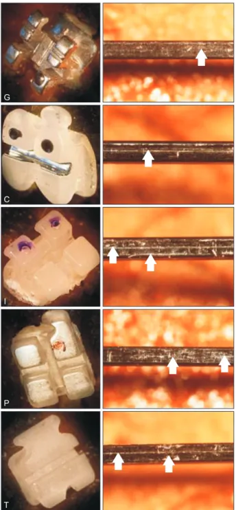
Representative light microscope images of the tested brackets and the archwires surfaces at the contact are shown in Figure 4. For all bracket/archwire combinations, a few scratches and grooves were noticed on the surfaces of the archwires, probably from the archwire drawing process.
DISCUSSION
The friction between archwires and brackets is influenced by many a variable, of which only a small fraction can be understood. Furthermore, there is no standardized method for precisely measuring the friction coefficients of the materials used in orthodontics.
Nonetheless, there are two main approaches for studying the frictional resistance between archwires and orthodontic brackets. One is in vivo simulations which estimate the friction from the speed of a single tooth or a group of teeth sliding along the archwire as in canine or en masse retraction cases; or by resolving the anterior crowding in alignment phase.
20However, in vivo studies can only measure the relative friction of the tested materials and are heavily influenced by uncontrollable biological factors which may be patient-related and thus may produce unstable results.
9The other approach is in vitro simulations which directly measures frictional forces as one tooth or a group of teeth move a certain distance along an archwire.
2,13Our study was performed with in vitro simulations in standardized laboratory condition to reinforce the shortcomings of in vivo environment and minimize the misleading effects of patient-related factors.
Figure 4. Post-experiment light microscope images of the tested brackets (left) and the archwires coupled with them (right). Arrows show the wear areas on the archwires. Letters indicate the group labels (G, Gemini metal; C, Clarity metal-slot ceramic; I, InVu ceramic; P, Pure ceramic; T, Transcend ceramic brackets).
Refer to Table 1 for the explanation about each product.
G
C
I
P
T