1. Introduction
AA7010 is an Al-Zn-Mg-Cu alloy containing Zr, devel- oped as an alternate to traditional AA7075 alloy owing to their high strength combined with better fracture toughness. While the Zr addition promotes fine grained structures, the low Fe and Si contents of the alloy improved the fracture toughness needed for aerospace application.
Kannan et al [1] while using a three step aging treatment (solution treatment-ST at 475 °C, water quenched at room temperature and aged at 100 °C /8 h followed by 120
°C /8 h and 170 °C /8 h) obtained better SCC resistance when compared to the alloy in the peak aged condition.
The better SCC resistance of the alloy in the overaged condition was reported to have a discontinuous and coarse grain boundary precipitates. Krishnan et al [2] adopted a modified heat treatment approach (130°C /0.5 h fol- lowed by 65°C /240 h and 130°C /24 h) and they have achieved strength levels close to peak aged condition and
SCC resistance equal to overaged condition. Similar im- provement in SCC resistance of the alloy in the overaged condition was reported by Puiggali et al [3] using slow strain rate test (SSRT) method in 3.5% NaCl solution.
However results on constant load test using smooth bar samples by Robinson et al [4] showed poor SCC resist- ance in the overaged condition when compared to under- aged and peak aged conditions.
Furthermore, Sc addition along with Zr in AA7010 re- sults in fine grained structure with better mechanical strength than Zr alone as a grain refiner. The combined effect of these elements resulted in un-recrystallized struc- ture which has good SCC resistance than recrystallized structure. It is also noted that reported results on this alloy were mostly in the form of plates that were obtained through hot rolling with thickness less than 5 mm [5,6].
It is equally important to study alloy forgings having high- er thickness in the range of 100-200 mm. In the aerospace industry, large sized components are fabricated through forging by thermomechanical working in perpendicular di- rections alternately to arrive at a desired three-dimensional
Effect of Microstructure on the Environmentally Induced Cracking Behavior of Al-Zn-Mg-Cu-Zr Aluminum Alloy
Rahul Ghosh1,†, A. Venugopal1, Pradeep P I1, L. Rama krishna2, P. Ramesh Narayanan1, Bhanu Pant1, and Roy M Cherian1
1Materials and Mechanical Entity, Vikram Sarabhai Space Centre, Thiruvananthapuram- 695 022, Kerala, India
2International Advanced Research Centre for Powder Metallurgy and New Materials (ARCI), Balapur P.O., Hyderabad 500005, India
(Received March 28, 2018; Revised April 23, 2018; Accepted April 25, 2018)
AA7010 is an Al-Zn-Mg-Cu alloy containing Zr, developed as an alternate to traditional AA7075 alloy owing to their high strength combined with better fracture toughness. It is necessary to improve the corrosion resistance and surface properties of the alloy by incorporating plasma electrolytic oxidation (PEO) method. AA7010-T7452 aluminum alloy has been processed through the forging route with multi-stage working operations, and was coated with 10µm thick Al2O3 ceramic aluminina coating using the plasma electrolytic oxidation (PEO) method. The corrosion, stress corrosion cracking (SCC) and nano-mechanical behaviours were examined by means of potentiodynamic polarization, slow strain rate test (SSRT) and nano-indentation tests. The results indicated that the additional thermomechanical treatment during the forging process caused a fully recrystallized microstructure, which lead to the poor environmental cracking resistance of the alloy in 3.5% NaCl solution, despite the overaging treatment.
Although the fabricated PEO coating improved general corrosion resistance, the brittle nature of the coating did not provide any improvement in SCC resistance of the alloy. However, the hardness and elastic modulus of the coating were significantly higher than the base alloy.
Keywords: Aluminum alloys, Potentiodynamic polarization, Stress corrosion cracking (SCC), Nanomechanical
†Corresponding author: [email protected]
shape with several intermediate heat treatments. The add- ed thermomechanical working will affect the micro- structure and the corrosion resistance of the alloy when compared to the alloy processed in the rolled form.
Therefore, it is necessary to improve the corrosion resist- ance and surface properties of the alloy by incorporating plasma electrolytic oxidation (PEO) method where the specimen is subjected to electrochemical oxidation at higher voltage resulting in formation of thick, hard, corro- sion resistant oxide layer. Limited results on magnesium alloys showed that the coating did not improve the SCC susceptibility of the alloys due to preferential cracking of the hard ceramic coating leading to penetration of corro- sive solution to the base metal [7,8]. The influence of PEO coating on the SCC resistance of high strength AA7010 aluminum alloy has not been studied and reported.
AA7010 aluminum alloy is reported to have varying levels of SCC resistance with change in microstructure.
Therefore, this work is aimed at (i) to evaluate the SCC resistance of the alloy in T7452 condition processed through hot forging route, (ii) to fabricate PEO coating on the alloy and to evaluate corrosion, nanomechanical as well as SCC resistance of the alloy in the un-coated and coated condition.
2. Experimental
2.1 Materials
AA7010 aluminum alloy having nominal composition Al-6.11Zn-2.32Mg-1.63Cu-0.05Fe-0.03Si-0.12Zr (wt%) was used in the form of forged blocks (200 mm thickness).
The blocks were realized through series of thermomechan- ical treatments and then heat treated to T7452 temper (solution treated at 475 °C for 8 h + stress relieved by 3% compression + aging at 120 °C for 13 h and sub- sequently 170 °C for 18.5 h). The achieved mechanical properties of the alloy were 502 MPa, 460 MPa, 11%
(UTS, YS, % Elongation). This alloy in the present con- dition was used as a substrate for plasma electrolytic oxi- dation (PEO) coating. Prior to coating, the specimens of AA7010 were polished on a series of SiC abrasive papers from 400-grit to 1000-grit and cleaned in acetone and dis- tilled water.
2.2 PEO coating process
An alkali silicate solution (4 g/L KOH, 2 g/L Na2SiO3) was used as an electrolyte and the coating process was carried out at a constant current density of 0.3 A/cm2 using a 50 Hz frequency AC high voltage power supply. The temperature of the electrolyte was maintained constant at 35 °C using a heat exchanger throughout the coating
process. The treatment time of the samples was 40 min.
The samples were taken out of the electrolyte, thoroughly washed in cold running water, ultrasonically cleaned in acetone medium and dried.
2.3 Microstructure and phase analysis
The coated samples were sectioned and polished down to 5 µm alumina finish followed by etching in Keller’s reagent (5 mL HNO3, 3 mL HCl, 2 mL HF and 190 mL distilled water) and were examined under optical and scan- ning electron microscopes (SEM) equipped with an energy dispersive X-ray spectrometer (EDX) for microstructural observations before and after coating using Carl-Zeiss EVO-50 scanning electron microscope (SEM). X-ray dif- fraction analysis was performed using PANalytical model X-ray diffractometer with Cu-Kα radiation between 20°
and 90° to identify the phases present in the coating.
2.4 Nanoindentaion tests
Elastic modulus (E) and hardness (H) of the PEO coat- ing and the substrate (AA7010-T7452) were obtained by nanoindentation tests in which a Berkovich diamond in- denter with a tip radius of 100 nm was mounted in order to carry out the indentations on the polished surface of the steel samples. A Nanoindenter supplied by CSM in- struments with a resolution of 50 nN in force and 0.01 nm in displacement was used. The loading and unloading time of 30 s, with 10 s hold at maximum load (20 mN) was adopted. For each depth level, 10 micro-indents were made and the hardness and reduced modulus values were extracted from the load-displacement curves using the Oliver and Pharr analysis [9]. Prior to making the tests on the samples, a calibration procedure was carried out on a commercial silica block provided by the supplier in which at least 10 indentations were made using the same Berkovich diamond indenter and the obtained elastic mod- ulus (E) was compared with the nominal elastic modulus of silica.
2.5 Scratch tests
Adhesion of the coating was evaluated using CSM mi- croscratch tester by creating a scratch on the as processed PEO coating surface. In this test, the load on a diamond Rockwell indenter with a tip radius of 100 mm was line- arly increased from 1 N to 15 N at a loading constant of 24 N/min. After the test, the scratch on the coating surface was examined under an optical microscope to de- termine the stages at which the coating failure happened.
The scratch tests were carried out in three steps. First, a “pre-scan was performed with same direction at a very low load (0.1 N) to determine the profile of the samples.
Secondly, the “true” scratch test was performed. Finally, a “post scan” was performed to determine the residual depth after elastic recovery. For each scratch test, the in- denter displacement, the applied normal force (Fn), the frictional force (Ft), the penetration depth (Pd), the residual penetration depth (Rd) and the specimen profile were ob- tained to determine the critical loads (Lc1 and Lc2). Tests were repeated for three times for reproducibility.
2.6 Electrochemical corrosion tests
Corrosion resistance of the uncoated and PEO coated specimens was evaluated through potentiodynamic polar- ization and impedance spectroscopy techniques using computer controlled Zhaner IM6ex electrochemical workstation. Unstirred 3.5% NaCl solution prepared with distilled water that has been exposed freely to the atmos-
phere was used as corrosive medium. Tests were carried out using a standard three-electrode setup with Pt as coun- ter electrode, saturated calomel electrode (SCE) as a reference. Impedance measurements were carried out on the uncoated and PEO coated specimens in the frequency range of 104–10-2 Hz with an amplitude of ±10 mV.
2.7 Slow strain rate test (SSRT)
SCC susceptibility of the coated and un-coated AA7010 alloy samples was evaluated by slow strain rate test (SSRT) method as per ASTM G129 at a strain rate of 6 x 10⁻⁷/s.
The tests were performed in 3.5% NaCl and air as the cor- rosive and reference environments, respectively. SSRT was performed using a CORTEST made CERT tensile testing machine. An acrylic container was used as a cell to hold the specimen and the environment. The gauge portion of
(a) (b)
Fig. 1 Optical micrographs of the AA7010-T7452 aluminum alloy.
(a) (b)
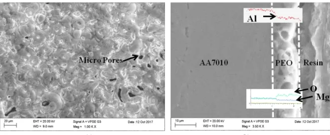
Fig. 2 SEM micrographs showing the surface (a) and cross section morphology (b) of the PEO coating on AA7010-T7452 alloy.
the samples was polished using 600-grit SiC paper on all the sides to obtain a smooth surface. The average elonga- tion of the specimen was measured by a pair of linear variable displacement transducers positioned on both sides of the specimen. The SCC index (SI), which is the ratio of elongation at the failure in the environment to that in air ε(NaCl)/ε(Air) was used as a measure to assess the SCC susceptibility.
3. Results and Discussion
3.1 Microstructure and phase analysis
The optical microstructure of the alloy presented in Fig.
1 exhibits fully recrystallized grains in which the fiber-like structure typical of thermomechanically treated structure is not seen. Few second phase particles appearing black in color are distributed in the matrix. These phases are constituent intermetallics particles as reported in the liter- ature [10,11]. Fig. 2 shows the surface (Fig. 2a) and cross section (Fig. 2b) of the PEO coating. Micro pores of diam- eter less than 8 µm are seen on the coating typical of PEO coating. The coating thickness is of the order of 10 µm as seen from the cross-sectional SEM image (Fig. 2 b). SEM-EDS line scan across the coating cross section revealed the presence of Al2O3 coating with minor Mg content diffused during PEO process.
Fig. 3 shows the XRD pattern of the PEO coated and uncoated AA7010-T7452 aluminum alloy. XRD analysis of the coating revealed that the coating consists of mainly γ-Al2O3 and few low intensity peaks of α- Al2O3. In addi- tion, peaks generating from the aluminum base metal can be seen due to x-rays penetration through the coating.
3.2 Electrochemical corrosion
Fig. 4 represents the impedance data obtained for the uncoated and PEO coated AA7010-T7452 alloy after im- mersion for 1 hour in 3.5% NaCl. The Bode plots in Fig.
4 indicate that the impedance values as seen from the low frequency end of the spectra are higher for PEO coated sample (2 x 10⁵ Ω cm2) than the uncoated (9 x 10² Ω cm2) alloy. This indicates that th e corrosion resistance of PEO coated alloy is better than the uncoated alloy.
Gradual decrease in phase angle with respect to frequency for the coated alloy can be ascribed to the porous nature of the coating as already indicated in Fig. 2. The polar- Fig. 3 XRD pattern of PEO coated and uncoated (base metal)
AA7010-T7452 aluminum alloy.
Fig. 4 Typical Bode impedance plots obtained for the uncoated and PEO coated AA7010-T7452 aluminum alloy: Impedance Vs. Frequency and Phase angle Vs. Frequency.
Fig. 5 Potentiodynamic polarization plots for the uncoated and PEO coated AA7010-T7452 aluminum alloy.
ization plots for the uncoated and PEO coated AA7010-T7452 alloy are represented in Fig. 5. An exami- nation of the plots shows that the corrosion potential (Ecorr) of the uncoated alloy is more active (-0.4V) than the PEO coated (-0.3 V) alloy. It also indicates that the corrosion current density (icorr) of the PEO coated alloy is one order magnitude lower than the uncoated alloy as a result of 10 µm thick PEO coating. Observation of the sample after polarization test revealed severe localized corrosion attack for uncoated alloy and its absence in the case of PEO coated alloy as depicted in Fig. 6a, b. Absence of localised attack in the case of PEO coated alloy as shown in Fig.
6b further corroborates better corrosion resistance.
3.3 Nanomechanical properties and scratch test
Typical load-displacement curves for uncoated and PEO coated alloy obtained from depth sensing indentation
measurements are shown in the Fig. 7. It can be seen that the elastic recovery of the PEO coated alloy is com- paratively higher than the uncoated sample as indicated by the shift in the indentation depth after the test. The hardness was calculated from the load and indentation depth data, and the modulus was determined from the un- loading response using the standard Oliver and Pharr tech- nique [9]. The indentation hardness and elastic modulus of the uncoated alloy were determined as 2.7 ± 0.2 GPa and 83 ± 10 GPa respectively. Similar values obtained for PEO coated alloy were 16 ± 2 GPa and 178 ± 10 GPa which are significantly higher than the uncoated alloy. The XRD results of the present study indicated the presence of mainly γ-Al2O3 (Fig. 3) having the reported hardness in literature of 17 GPa which is excellent agree- ment with the hardness (16 ± 2 GPa) achieved in the pres- ent work.
It was also reported that the alloying elements such as Mg and Zn ions diffusing from the base metal increase the transformation temperature of γ-α Al2O3, resulting in lower α-Al2O3 [12]. In the present work the, the presence of higher Mg and Zn content helps in retaining γ- Al2O3
in the PEO coating.
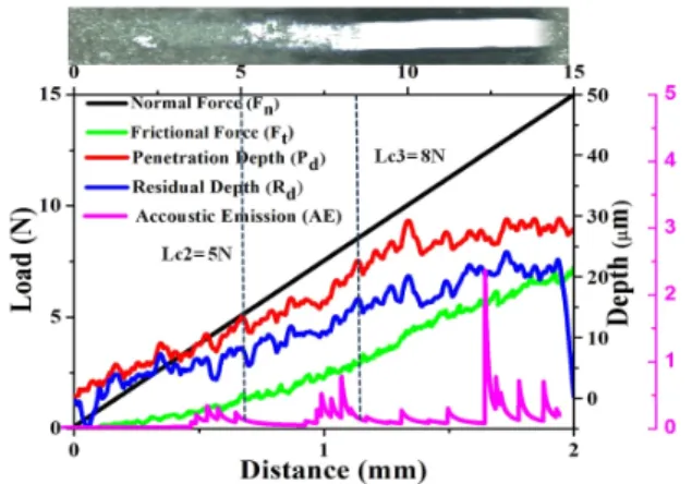
The mechanical, general corrosion and the stress corro- sion resistance of the coating are determined by the adhe- sion of the coating with the base metal. In order to under- stand the adhesion behavior, scratch tests were performed on the PEO coated alloy. The optical image of the scratch and the other scratch test results such as acoustic emission, frictional force, penetration depth and residual depth re- corded during the scratch tests are shown in Fig. 8.
By comparing the optical images and the acousting emission signals shown in Fig. 8, distinct regions could
(a) (b)
Fig. 6 Corrosion morphology of (a) uncoated and (b) PEO coated AA7010-T7452 aluminum alloy after polarization tests in 3.5%
NaCl solution.
Fig. 7 Typical load-depth data obtained during indentation tests on uncoated and PEO coated AA7010-T7452aluminum alloy.
be marked indicating different damage levels. The critical loads determined at these locations are Lc1=2.5 N, Lc2=
5N and Lc3= 8N. The PEO coating damage at Lc1 and Lc2 can be attributed to the cohesive damage of the coating. This could be due to the porous nature of the coating as already shown in Fig. 2. After a certain load due to continuous perforation complete damage of the coating by spallation has occurred revealing the under- lying base metal. However, no delamination of the coating has taken place at the border or outside the scratch track.
The measured Lc3 value (8N) and the corresponding fric- tional force (4 N) are slightly lower than the values re-
ported for AA7075 alloy [13], probably due to lesser thickness (10 µm) used in the present work. Beyond Lc3, further increase in load causes marginal fluctuation in pen- etration depth due to chipping of the metal and its inter- action with the scratch indentor.
3.4 Stress corrosion cracking (SCC) test
The stress-strain curves obtained for the uncoated and PEO coated AA7010-T7452 alloy specimens are presented in Fig. 9. The SSRT data such as UTS, % El and SCC index obtained from the SSRT plots are shown in Table 1. It can be seen that the UTS values are comparable for both uncoated and coated samples in both environments.
However, significant reduction in elongation values can be noted for both uncoated and coated samples after ex- posing to 3.5% NaCl solution. For the uncoated sample the elongation has decreased from 11.90% (air) to 4.5%
(NaCl). As a result of this, the SCC index (ε(NaCl)/ε(Air)) was very low (0.38) which is the ratio of the elongation of the samples tested in 3.5% NaCl solution and the air.
The greater the SI value, the better the SCC resistance.
An index value of unity implies that the material exhibits no SCC susceptibility. The poor SCC index value (0.38) measured for the uncoated alloy indicates that the alloy is highly susceptible to SCC. In the case of PEO coated sample also the measured index value was very low (0.45) which is similar to that of uncoated sample. This shows that the fabricated PEO coating did not provide any resist- ance towards SCC for this alloy. Further examination of the fractured samples under SEM showed typical inter- granular cracking mode of failure for both uncoated and coated samples exposed to 3.5% NaCl solution. However, the air tested sample exhibited predominantly ductile mode of failure.
The earlier published results of this alloy were mostly in the form of wrought product which had clear un- recrystallized fiber like pancake shaped microstructure and as a result of this good SCC resistance was obtained. In the present study, in spite of the overaging treatment the alloy AA7010-T7452 exhibited poor SCC resistance. This can be due to the additional thermomechanical treatment carried out on the alloy during the forging process. The intermittent pre-heating treatment during the forging proc- ess has resulted in fully recrystallized structure and its subsequent grain growth solution treatment. This as a re- sult provided easy crack propagation along the grain boun- daries as noted in the present work. Reported results in- dicate that combined effect of Sc and Zr [5,6] in the alloy AA7010 provides good SCC resistance and also recrystal- lization inhibition by forming homogeneously distributed Al3ScxZ1-x dispersoids. Hence we believe that instead of Table 1 Mechanical parameters obtained from SSRT tests in
3.5 wt% NaCl Sample
index UTS, MPa Elongation % SCC index Uncoated Air
NaCl 503 485
11.90
4.50 0.38
PEO Coated Air NaCl
494 489
9.14
4.19 0.45
Fig. 8 Optical micrograph and measured scratch performance of PEO coated AA7010-T7452 aluminum alloy.
Fig. 9 Stress vs Strain plots obtained for uncoated and PEO coated AA7010-T7452 alloy.
Zr alone as a grain refiner, addition of Sc along with Zr could provide potential benefits towards SCC resistance of the alloy AA7010 processed through forging route with additional thermomechanical treatment. The results ob- tained in the present study further implies that overaging treatment with typical coarse discontinuous precipitates along with grain structure is important for the SCC resist- ance of high strength aluminium alloys. Furthermore, the fabricated PEO coating could not improve the SCC resist- ance of the alloy as the fracture morphology is similar to the uncoated alloy. This can be attributed due to the brittle nature of the coating as seen from the nano-in- dentation results. These results are similar to reported re- sults on PEO coated magnesium alloys. However the gen- eral corrosion resistance of the coating was found to be better as seen from the electrochemical polarization results. These results are in line with the other reported results in literature on aluminium and magnesium alloys [7,8,14].
4. Conclusions
AA7010-T7452 (Al-Zn-Mg-Cu-Zr) alloy processed through forging route involving multistage working with
more pre-heating operations having fully recrystallized structure was used in the present study to (i) to evaluate the SCC resistance of the alloy in T7452 condition (ii) to fabricate PEO coating on the alloy and to evaluate cor- rosion, nanomechanical as well as SCC resistance of the coated alloy. The significant findings are given below:
(a) AA7010-T7452 alloy used in the present work ex- hibited completely recrystallized microstructure. This is attributed to the intermittent pre-heating steps during forg- ing operations resulting in dynamically recrystallized structure and its subsequent grain growth during solution treatment
(b) As a result of the recyrstallized microstructure, the alloy exhibited poor SCC resistance as seen from the SSRT results. Although the alloy was subjected for over- aging treatment the potential benefit of such treatment is lost due to the recrystallized microstructure and hence failed predominantly with intergranular fracture mode.
Similar observations were also made for PEO coated al- loy, which failed to prevent SCC due to presence of micro pores in the coating which allowed easy diffusion paths for electrolyte.
(c) The PEO coating (10 µm) on the AA7010-T7452 Fig. 10 Fracture morphology of uncoated (a,b) and PEO coated (c,d) samples after SSRT in air and 3.5% Nacl solution.
aluminum alloy could not provide complete protection against environmental cracking resistance of the alloy al- though it has improved the general corrosion resistance of the alloy to some extent. However, the PEO coating offered good improvement in the hardness and elastic modulus when compared to the base metal.
Acknowledgments
The authors express their sincere thanks to Director, VSSC for permitting to publish the paper.
References
1. M. Bobby Kannan, V. S. Raja, R. Raman, and A. K.
Mukhopadhyay, Corrosion, 59, 881 (2003).
2. M. Ajay Krishnan and V. S. Raja, Corros. Sci., 109, 94 (2016).
3. M. Puiggali, A. Zielinski, J. Molive, E. Renauld, D.
Desjardins, and M. Cid, Corros. Sci., 40, 805 (1998).
4. J. S. Robinson, Mater. Sci. Forum, 331-337, 653 (2000).
5. M. Bobby Kannan and V. S. Raja, Eng. Fract. Mech., 77, 249 (2010).
6. Ying Deng, Zhimin Yin, Kai Zhao, Jiaqi Duan, Jian Hu, and Zhenbo He, Corros. Sci., 65, 288 (2012).
7. P. Bala srinivasan, C. Blawert, W. Dietzel, and K.U.
Kainer, Scr. Mater., 59, 43 (2008).
8. P. Bala Srinivasan, C. Blawert, and W. Dietzel, Mater.
Sci. Eng. A, 494, 401 (2008).
9. W. C. Oliver and G. M. Pharr, J. Mater. Res., 7, 1564 (1992).
10. M. Bobby Kannan and V. S Raja, J. Mater. Sci., 42, 5458 (2007).
11. M. Bobby Kannan and V. S Raja, Metall. Mater. Trans., 38A, 2843 (2007).
12. Y. J. Oh, J. I. Mun, and J. H. Kim, Surf. Coat. Technol., 204, 141 (2009).
13. T. Arunnellaiappan, N. Kishore babu, L. Rama Krishna, and N. Ramesh Babu, Surf. Coat. Technol., 280, 136 (2015).
14. Hossein Fadaee and Mehdi Javidh, J. Alloy. Compd., 604, 36 (2014).