논문 2011-4-36
통신 시스템간 채널 공유를 위한 특성 분석
Analysis on Characteristics for Sharing Co-channel between Communication Systems
조주필*, 조상인**, 강규민**, 홍헌진**
Juphil Cho,Sang-In Cho, Kyu-Min Kang, Heon-Jin Hong
요 약 본 논문은 채널 공유를 위한 기준 간섭확률 대비 두 시스템인
WiBro
와WLAN
간의 이격거리를 분석하여 상 용화의 기준 자료가 되도록 하였다. Monte-Carlo
방법에 기초한Spectrum Engineering Advanced Monte Carlo Analysis Tool(SEAMCAT)
을 이용하여TV White Spaces(TVWS)
대역의 동일 및 인접채널에서WiBro
가 무선랜에 미치는 간섭 확률 및 그 영향을 분석하였다.
분석 결과,
동일채널에서WiBro Mobile Station(MS)
의 최대 송신파워(25 dBm)
를 허용 하기 위해WiBro MS
와 무선랜User Equipment(UE)
사이에210 m
의 이격거리가 요구된다.
또한, WiBro Base Station(BS)
의 송신파워는-4.96 dBm
으로 감소되어야 한다.
Abstract In this paper, we analyze the distance between two systems, WiBro and WLAN, compared to standard interference probability for channel co-use in order to be used as a criteria in realization. Co-channel and adjacent channel interference probability and its effect of (WiBro) into Wireless LAN (WLAN) in TV White Spaces (TVWS) is evaluated through Spectrum Engineering Advanced Monte Carlo Analysis Tool (SEAMCAT) based on the Monte-Carlo simulation method. As a result, in the case of co-channel interference, the minimum distance between WiBro Mobile Station (MS) and WLAN User Equipment (UE) should be 210 m to allow the maximum transmitter power of WiBro UE of 25 dBm. The transmit power of WiBro BS have to be reduced to -4.96 dBm.
Key Words : WiBro, WLAN, TVWS, SEAMCAT, Guard band
*정회원, 군산대학교 전파공학과
**한국전자통신연구원(ETRI)
접수일자 2011.7.12, 수정일자 2011.8.10 게재확정일자 2011.8.12
Ⅰ. Introduction
An important benefit of the switch to all-digital broadcasting is that it freed up parts of the valuable broadcast spectrum for public safety communications (such as police, fire departments, and rescue squads) and applications on an unlicensed, such as Wi-Fi in TV White Spaces (TVWS). Also, some of the spectrum
can now be auctioned to companies that will be able to provide consumers with more advanced wireless services[1]. WLAN is assumed to operate at 481 MHz.
And WiBro is assumed to operate at co channel with WLAN or adjacent channel to WLAN. Based on previous assumptions, WLAN and WiBro potentically interfere each other. This paper only analyzes WiBro interferers with WLAN, two scenarios will be analyzed as following: scenario1: WiBro mobile station (MS) interferes into WLAN user equipment (UE). scenario2:
WiBro BS interferes into WLAN UE. Therefore,
protection distance between WLAN UE and WiBro MS, the maximum allowable transmit power of WiBro MS and BS and guard band are respectively analyzed by using Spectrum Engineering Advanced Monte Carlo Analysis Tool (SEAMCAT).
Ⅱ. System Descriptions
A. WLAN
A WLAN typically extends an existing wired local area network. WLANs are built by attaching a device called the access point (AP) to the edge of the wired network. Clients communicate with the AP using a wireless network adapter which is similar in function to a traditional Ethernet adapter.
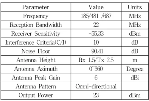
표 1. WLAN의 주요 변수
Table 1. Main parameters of WLAN
Parameter Value Units
Frequency 185/481 /687 MHz
Reception Bandwidth 22 MHz
Receiver Sensitivity -55.33 dBm Interference Criteria(C/I) 10 dB
Noise Floor -90.41 dB
Antenna Height Rx 1.5/Tx 2.5 m Antenna Azimuth 0~360 Degree
Antenna Peak Gain 6 dBi
Antenna Pattern Omni-directional
Output Power 23 dBm
WLANs are being widely used in private home, business and hotspots (such as coffee shop, conference and airport,etc.). Main parameters of WLAN are summarized in Table 1
[3]. Blocking response of WLAN receiver is summarized in Table 2
[4].
표 2. 블록 응답
Table 2.Blocking response
Frequency offset [MHz] Attenuation [dBr]
±11 0
±25 38
±50 53
>50 63
B. WiBro
WiBro is the Korean service name for IEEE802.16e international standard. Comparing to WLAN, WiBro supports mobility up to walking speed and vehicles peed and wider coverage. Main parameters of WiBro are assumed in Table 3.
Spectral mask for WiBro MS is summarized in Table 4
[5].
Spectral mask for WiBro BS is summarized in Table 5
[6].
표 3. 와이브로의 주요 변수
Table 3. Main parameters of WiBro
Parameter Value Units
Frequency Co/adjacent channel
with WLAN MHz
Bandwidth 10 MHz
Base station(BS)
Transmit power 33 dBm
Antenna hight 30 m
Mobile Stations (MS)
Transmit power 25 dBm
Antenna height 1.5 m
Noise floor -107 dBm/MHz
Noise Figure 7 dB
S/N 9.4 dB
Sensitivity -90.6 dBm
표 4. 와이브로 단말 스펙트럼 마스크(출력=25dBm) Table 4. WiBro MS spectral mask @Pout=25dBm
Frequency offset
[MHz] Attenuation [dBc]
Reference Bandwidth
[kHz]
-5~+5 0 10000
±5.45 -36 100
±10.9 -42 100
±15.12 -48 100
±20.26 -52 100
±80 assumed -82 100
표 5. 와이브로 기지국 스펙트럼 마스크 Table 5. WiBro BS spectral mask
Frequency offset
from centre Allowed
emission level Measurement bandwidth 5 ≤
Δf < 6 MHz −13 dBm 100 kHz 6 ≤
Δf < 25 MHz −13 dBm 1 MHz 25 ≤
Δf < 70MHz
(assumed) −28 dBm 1 MHz
Ⅲ. Scenarios of WiBro Interfering with WLAN and Methodology
Indoor deployment environment in urban is chosen and two scenarios will be assumed subsequently:
Scenario 1: WiBro MS interferes with WLAN UE.
This scenario is further divided into two scenarios which are illustrated in Figure 1 and Figure 2, respectively.
그림 1. WLAN 단말과 단일 와이브로 단말간 간섭 시나리오 Fig. 1. Scenario of single WiBro MS interferences
with WLAN UE
그림 2. WLAN 단말과 다중 와이브로 단말간 간섭 시나리오 Fig. 2. Scenario of multiple WiBro MSs interfere
with WLAN UE
Scenario 2: Closest Seven WiBro BSs interfere with WLAN is considered in Figure 3.
The criterion for interference to occur is for the victim receiver (Vr) to have a carrier to interference ratio (C/I) less than the minimum allowable value. In order to calculate the victim’s C/I, it is necessary to establish the victim’s wanted signal strength/dRSS corresponding to the C, as well as the interfering received signal strength (iRSS) corresponding to the I.
Figure 4 illustrates the various signal levels.
그림 3. WLAN 단말과 다중 와이브로 기지국간 간섭 시나리 오
Fig. 3. Scenario of multiple WiBro BS interfere with WLAN UE
Figure 4 (a) represents the situation when there is no interference and the victim is receiving the desired signal with wanted signal margin.
그림 4. 간섭 발생여부를 결정하기 위한 신호레벨
Fig. 4. The signal levels used to determine whether or not interference is occurring
Figure 4 (b) illustrates what happens when interference occurs. The interference adds to the noise floor. The difference between the wanted signal strength and the interference signal is measured in dB, which is defined as the Signal to Interference ratio.
This ratio must be more than the required C/I threshold if interference is to be avoided. The Monte Carlo simulation methodology is used to check for this condition and records whether or not interference is occurring.
Ⅳ. Simulation Results and Analysis
Propagation model for different links are separately
Appointed guard band
(MHz)
Maximum allowable transmit power of WiBro MS (dBm)
WLAN: 481 MHz WiBro: 497MHz + guard band
Density of interferers/km
250 100 150 200
0 27.0 22.5 19.35 17.7
2 32.7 28.2 25.8 23.4
4 34 29.8 27.2 25.2
assumed as follows: Extended Hata SRD model for victim link WLAN (Wt: Wanted transmitter -> Vr:
Victim receiver), Extended Hata is for interfering link WiBro (It: Interfering transmitter -> Wr: Wanted receiver) and Extended Hata SRD model for interference link (It: Interfering transmitter -> Vr:
Victim receiver). On the basis of previously introduced system parameters, interference scenarios and interference probability of 5% blow is chosen as an acceptable level for performance requirement of WLAN, co channel and adjacent channel interferences from WiBro to WLAN UE will be evaluated in SEAMCAT, respectively.
A. Co channel interference
In the scenario of co channel interference from WiBro to WLAN UE, WiBro and WLAN operating at the same frequency of 481 MHz is assumed. And then, the protection distance between WiBro MS and WLAN UE and the maximum allowable transmit power of WiBro MS and BS will be evaluated.
In case of single WiBro MS interfering into WLAN UE, according to the specified transmits power of WiBro MS of 25 dBm, the protection distance between WiBro MS and WLAN UE is evaluated to meet the acceptable interference probability of 5%. The relationship between interference probability of WiBro MS interfering with WLAN UE and the protection distance between WiBro MS and WLAN UE is obtained in Figure 5. Figure 5 shows if the specified WiBro MS transmit power of 25 dBm is used, the protection distances between WiBro MS and WLAN UE is supposed to be more than 210 m corresponding to 481 MHz.
In addition, according to different required protection distances between WiBro MS and WLAN UE, the corresponding maximum allowable transmit power of WiBro MS can be figured out through simulation.
그림 5. WLAN 단말과 와이브로 단말간 거리에 따른 간섭 확 률
Fig. 5. Interference probability vs. the distance between WiBro MS and WLAN UE
B. Adjacent channel interference
In scenario of adjacent channel interference from WiBro to WLAN, the case of multiple WiBro MSs interfering with WLAN UE is taken into account, Density of interferes/km
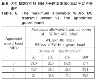
2of 50, 100, 150 and 200 and the protection distance of 1 m are assumed. And then, according to different required guard bands, the maximum allowable transmit power of WiBro MS is evaluated through simulation. The results are summarized in Table 6.
표 6. 지정 보호대역 대 허용 가능한 최대 와이브로 단말 전송 출력
Table 6. The maximum allowable WiBro MS transmit power vs. the appointed guard band
Table 6 shows that when density of interferers equals to 200, interference situation of WiBro MS interfering with WLAN UE is the worst case.
Therefore, the guard bands should be more than 4 MHz
※ 본 연구는 지식경제부 및 산업기술개발평가원의 정보통신 산업원천기술개발사업의 일환으로 수행하였음.
[2009-F-035-01, 10GHz 이하 대역에서 Dynamic Spectrum Access를 위한 상호 공존성(Coexistence) 기준 연구].
corresponding to 481 MHz for meeting the specified transmit power of WiBro MS of 25 dBm.
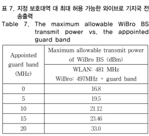
In the case of multiple WiBro BSs interfering with WLAN UE, according to different required guard bands, the maximum allowable transmit power of WiBro BS is evaluated through simulation. The results are summarized in Table 7. Table 7 shows that the guard band of 20 MHz at 481 MHz is able to meet the specified transmit power of WiBro BS of 33 dBm.
표 7. 지정 보호대역 대 최대 허용 가능한 와이브로 기지국 전 송출력
Table 7. The maximum allowable WiBro BS transmit power vs. the appointed guard band