Original Article
Verification of Mechanical Leaf Gap Error and VMAT Dose Distribution on Varian VitalBeam TM Linear
Accelerator
Myeong Soo Kim*, Chang Heon Choi*,†, Hyun Joon An*,†, Jae Man Son†, So-Yeon Park‡
*Biomedical Research Institution, Seoul National University Hospital, †Department of Radiation Oncology, Seoul National University Hospital, ‡Department of Radiation Oncology, Veterans Health Service Medical Center, Seoul, Korea
Received 28 May 2018 Revised 12 June 2018 Accepted 20 June 2018
Corresponding author So-Yeon Park ([email protected]) Tel: 82-2-2226-4648 Fax: 82-2-2225-4640
The proper position of a multi-leaf collimator (MLC) is essential for the quality of intensity- modulated radiation therapy (IMRT) and volumetric modulated arc radiotherapy (VMAT) dose delivery. Task Group (TG) 142 provides a quality assurance (QA) procedure for MLC position. Our study investigated the QA validation of the mechanical leaf gap measurement and the maintenance procedure. Two VitalBeamTM systems were evaluated to validate the acceptance of an MLC position. The dosimetric leaf gaps (DLGs) were measured for 6 MV, 6 MVFFF, 10 MV, and 15 MV photon beams. A solid water phantom was irradiated using 10×10 cm2 field size at source-to- surface distance (SSD) of 90 cm and depth of 10 cm. The portal dose image prediction (PDIP) calculation was implemented on a treatment planning system (TPS) called EclipseTM. A total of 20 VMAT plans were used to confirm the accuracy of dose distribution measured by an electronic portal imaging device (EPID) and those predicted by VMAT plans. The measured leaf gaps were 0.30 mm and 0.35 mm for VitalBeam 1 and 2, respectively. The DLG values decreased by an average of 6.9% and 5.9% after mechanical MLC adjustment. Although the passing rates increased slightly, by 1.5% (relative) and 1.2% (absolute) in arc 1, the average passing rates were still within the good dose delivery level (>95%). Our study shows the existence of a mechanical leaf gap error caused by a degenerated MLC motor. This can be recovered by reinitialization of MLC position on the machine control panel. Consequently, the QA procedure should be performed regularly to protect the MLC system.
Keywords: Optimization of mechanical leaf gap, Dosimetric leaf Gap, PDIP calculation
Copyright © 2018 Korean Society of Medical Physics
CCThis is an Open-Access article distributed under the terms of the Creative Commons Attribution Non-Commercial License (http://creativecommons.org/licenses/by- nc/4.0) which permits unrestricted non-commercial use, distribution, and reproduction in any medium, provided the original work is properly cited.
Introduction
Multi-leaf collimators (MLCs) are essential components of intensity-modulated radiation therapy (IMRT) and volu- metric modulated arc therapy (VMAT) for shaping a radia- tion beam along a treatment field. MLC was introduced clinically to deliver static field treatments and have recently been used in intensity modulated field treatments with dynamic multi-leaf collimation.1) Since then, related MLC
technologies have been rapidly developed in terms of MLC design characteristics and techniques of leaf position con- trol. An accuracy of dose delivery in radiotherapy depends upon appropriate accounting of the MLC characteristics such as shape of leaf ends, leaf transmission, leaf scatter, and collimator scatter upstream from the MLC.2)
Technically, the shape of the leaf ends differs from one manufacturer to another. Single-focused leaves (Electra and Varian) are rounded while double-focused leaves
Progress in Medical Physics 29(2), June 2018 https://doi.org/10.14316/pmp.2018.29.2.66 eISSN 2508-4453
(Siemens) have flat leaf ends. Varian introduced the single focused leaves, which have round shaped leaf ends and tongue-and groove.3) The rounded leaf ends are designed to reduce a wider penumbra width generated from flat leaf edges. The degree roundedness of the leaf ends is de- termined by considering beam divergence while the leaf tips are positioned at various distances from the central isocenter across the field. A transmitted radiation leakage is induced through the two rounded leaves referred to the dosimetric leaf gap (DLG).4,5)
There are several issues with the QA program related to the MLC system. It is not only the MLC position but also the mechanical leaf gap width between a pair of leaves.
Varian’s specification defines that the mechanical leaf gap width between the two opposing flat sides should be 0.5 mm. Inaccurate leaf gap width may lead to problems such as undetectable micro collision. This mechanical impact may cause failure of individual motor. In recent times, we experienced several MLC motor breakdowns due to me- chanical errors of MLC gaps. However, this problem has been solved by MLC gap adjustment by re-initializing the resetting of all MLC encoders.
In this study, the focus is on appropriate maintenance for optimizing MLC leaf gap width in radiation treatment system. It is a specific QA procedure supported by the manufacturer. We investigated validation of the mechani- cal measurement of the leaf gap width and the reinitializa- tion procedure of a millennium 120 MLC system in Varian VitalBeamTM system.
Materials and Methods
1. Mechanical MLC gap revision
The leaf gap width of MLCs was mechanically measured and adjusted on two Varian VitalBeamTM (Varian Medi- cal Systems, Palo Alto, CA) linear accelerators mounted with millennium 120 MLC system. Two linear accelerators have been properly commissioned and maintained in ac- cordance with AAPM Task Groups (TGs) specifications.
For measuring the leaf gap width mechanically, the gantry head was set to 180 degree to open MLC system and 2 op- posing leaves were aligned along the central axis to mea- sure the leaf gap width. A filler gauge, which consists of metal plates of varying thicknesses (Fig. 1(b)), was insert- ed, one plate at a time from thinner to thicker, into the gap of aligned MLCs to measure the leaf gap width. Mechanical differences of MLC gap corresponding to the tested linear accelerators were precisely adjusted to 0.5 mm by chang- ing the gap value on the machine control panel.
2. DLG assessments
For the evaluation of accuracy of the obtained leaf gap values, the DLGs of two MLC systems were investigated before and after the mechanical calibration. We performed the DLG measurement as per a method suggested from Varian’s guideline. Measurements were implemented for 6 MV, 6 MV-flattening filter-free (FFF), 10 MV, and 15 MV photon beams in 30×30 cm2 solid water phantom (Standard
a b
Leaf gap
Bank A Bank B
Filler gauge
Fig. 1. Mechanical multi-leaf collima- tor (MLC) gap measurement. (a) Millennium 120 MLCs of VitalBeamTM accelerator in a 180° rotated position for measuring actual leaf gap width (b) a filler gauge used for leaf gap width assessment.
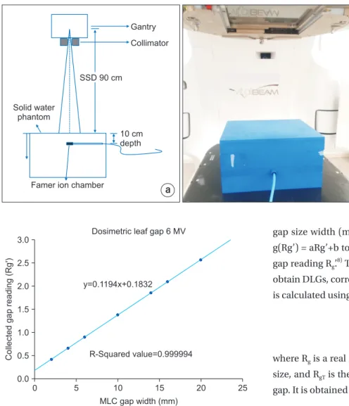
Imaging, Middleton WI, USA) at 90 cm source to surface distance. The Farmer ionization chamber (PTW, Germany) with 0.6 cm3 was placed at 10 cm depth within the solid water phantom and was irradiated using a 10×10 cm2 field size. DLG are commonly measured with distinct uniformed extension of synchronized dynamic MLC sweeping gap field. The DLGs were measured with 2, 4, 6, 10, 14, 16, and 20 mm MLC gap widths and the gaps moved from −60 mm to +60 mm at a constant speed with respect to 100 MU to a delivery dose.
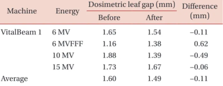
Various methods for measuring a DLG size were suggest- ed in several studies.6,7) We used a methodology described by LoSasso et al.1) DLG is obtained from the graph in which the corrected gap reading is plotted against each tested
gap size width (mm). A predicted trend-line is defined as g(Rg’) = aRg’+b to points given by gap size g and corrected gap reading Rg’.8) The intercept value of b is the DLG and to obtain DLGs, corrected gap reading (Rg’) for each gap (mm) is calculated using the following equation.
….……….. (1)
where Rg is a real reading value corresponding to each gap size, and RgT is the average MLC leaf transmission for each gap. It is obtained from the following equation.
] 120[
] - [ 1
=
R
………. (2)
RT is the average transmission reading, which is calcu- lated as follows.
2 ……… (3)
where RT,A and RT,B represent the MLC transmission reading for MLC bank A and B. Ropen is the dose measured for open field.
3. Calculation of PDIP (portal dose image prediction)
To evaluate the MLC system for VMAT beams, we per- formed an evaluation using a comparison of difference
Collectedgapreading(Rg')
0 3.0
2.5
2.0
1.5
1.0
0.5
MLC gap width (mm) 0.0
y=0.1194x+0.1832
R-Squared value=0.999994
25 20
15 10
5
Dosimetric leaf gap 6 MV
Fig. 3. Example of predicted linear dependence for 6 MV photon beam and equation for obtaining the absolute value of b in order to seek the dosimetric leaf gap (DLG).
a b
Solid water phantom
SSD 90 cm Gantry Collimator
10 cm depth
Famer ion chamber
Fig. 2. The dosimetic leaf gap (DLG) mea sure ment using ionization cham ber and solid water phantom: (a) schematic design and (b) solid water phantom (30 cm×30 cm), and fa mer ion-chamber on a couch in VitalBeamTM.
between the dose distribution calculated from treatment planning system (TPS) and that actually delivered. We ob- tained the predicted dose from a PDIP algorithm to VMAT beams and the computational prediction was implement- ed on commercially available treatment planning system (TPS) which is Varian’s EclipseTM (Varian Medical Systems, Palo Alto, CA). The TPS PDIP algorithm in the software tool utilized an incorporated correction factors to generate the predicted electronic portal imaging device (EPID) im- age to account for the difference in EPID response to the open beam radiation and MLC transmitted radiation. The EPID is being used in radiotherapy to achieve an accurate dose assessment. First, it produces images almost instan- taneously and saves the images digitally on a computer.
Second, it is available as a treatment field verification dur- ing the treatment gives the quality treatment. Third, images will be available immediately for reference and so on.10)
VMAT plans with two full arcs, which were previously used for patient treatments, were retrospectively selected.
A total of 20 VMAT treatment plans corresponding to the two VitalBeamTM linear accelerators were analyzed in this study. The treatment sites were various, which were brain, head and neck (H&N), and prostate. This evaluation pro- cess was performed twice, before and after the mechanical measurement and a correction of the MLC gap position.
Dose agreement between the PDIP and the acquired EPID image was analyzed by using global gamma (r) passing rates proposed by Low et al.11) The Gamma passing rate has the criteria of 3%/3 mm, and a value of 95% or more is considered to be clinically accepted value.9,12,13) A mean gamma pass rate was analyzed on a relative, absolute, and composite dose difference.
Results
1. DLG assessment
The mechanically measured MLC gap distances of 0.3 mm and 0.35 mm correspond to the VitalBeam 1 and 2, respectively. The gap sizes measured using the filler gauge were closer than optimal size, 0.5 mm. Table 1 and 2 sum- marize the results of DLG value measured with ionization chamber, and compare the variation between the results before and after the mechanical correction. A transmitted dose distribution was measured for a 10 cm×10 cm MLC field at 10 cm depth using a Farmer ion-chamber. Fig. 1 displays a trend-line of measured DLG values correspond- ing to the corrected gap reading at points. The tested MLC sliding points were 2, 4, 6, 10, 14, 16, and 20 mm. The DLG sizes for 6 MV low energy beam tend to be slightly de- creased from 1.650 (before calibration) to 1.536 mm (after calibration) in both the machines. The DLG value of 10 MV photon beam is also reduced from 1.875 mm to 1.389 mm in VitalBeam 1 (1.485 mm in VitalBeam 2). The differences of DLG values for the 6 MVFFF increased as a 0.62 mm and 0.23 mm to both the VitalBeamTM systems. In 15 MV beam of VitalBeam 1, a little difference between before and after is tabulated in Table 1. Average deviations of DLG values between pre and post MLC correction were 0.11 mm (6.9%
decreased) and 0.09 mm (5.9% decreased) in the two linacs, respectively. The results show that no significant difference was found between the two linear accelerators (P<0.01).
2. PDIP calculation
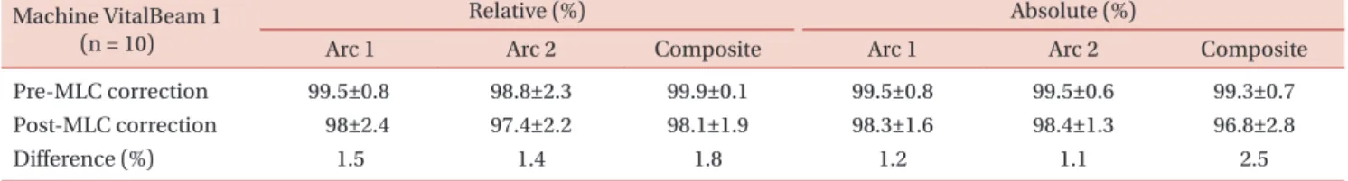
Table 3 and 4 summarize the results of the PDIP calcula- tion in order to validate the accuracy of MLC leaf position.
Table 1. The measured dosimetric leaf gap (DLG) result with an ionization chamber in VitalBeam 1.
Machine Energy Dosimetric leaf gap (mm) Difference Before After (mm)
VitalBeam 1 6 MV 1.65 1.54 −0.11
6 MVFFF 1.16 1.38 0.62
10 MV 1.88 1.39 −0.49
15 MV 1.73 1.67 −0.06
Average 1.60 1.49 −0.11
Table 2. The measured dosimetric leaf gap (DLG) result with an ionization chamber in VitalBeam 2.
Machine Energy Dosimetric leaf gap (mm) Difference Before After (mm)
VitalBeam 2 6 MV 1.65 1.54 −0.11
6 MVFFF 1.16 1.39 0.23
10 MV 1.88 1.49 −0.39
Average 1.56 1.47 −0.09
The calculated passing rates were obtained with EclipseTM and this software tool used the DICOM RT image from the EPID. Two VMAT arcs were acquired to verify the validation of MLC and plan data from ten patients were utilized for this evaluation. Averaged passing rates of Vital- Beam 1 with relative analysis decreased from 99.5%±0.8%
to 98.8%±2.4% in VMAT arc 1. It decreased slightly to 98.8%±2.3% and 97.4%±2.2% in arc 2 also, as tabulated in Table 3. Table 4 shows that VitalBeam 2 also exhibited a small reduction in the averaged passing rate, which is simi- lar to that of VitalBeam 1. Mostly the average gamma pass- ing rates were slightly reduced after the mechanical leaf correction in Table 3 and 4. However, the validity of passing rate was still within the good dose delivery level (>95%).
Furthermore, a composite calculation of the VMAT arc 1 and 2 shows no significant difference between VitalBeam 1 and VitalBeam 2 (P<0.05).
Discussion
In this study, MLC system was investigated to validate the QA procedure of mechanical MLC leaf gap. The evalu- ated DLG values with 6 MV, 10 MV, and 15 MV were re- duced from an MLC correction but it was not so with the 6 MVFFF. The DLG size with 6 MVFFF was lower than that of the other beams. This is because a flattening filter free causes softening of beam spectrum and it can lead to a re- duction in DLG value.14) After the MLC correction, the leaf gap increased from 0.3 mm to 0.5 mm. It tends to increase
the DLG size in case of the flattening filter free. The results of PDIP calculation showed gamma passing rates within a criterion 3%/3 mm. Thus, the processed MLC leaf correc- tion is valid for a QA procedure to VitalBeamTM system.
Resolutions of MLC system define the quality of the IMRT and VMAT dose delivery.1) VitalBeamTM has a round- ed end Millennium 120 MLC and it is designed to reduce immoderate wider penumbra caused from flat-type leaf edges.4) Although this design can reduce the penumbra size, and it can lead to a significant dose variation between treatment planning and delivered dose distributions. The variation is affected by a beam transmission that passes through from the rounded leaf end to leaf end along the vertical axis of MLCs. The beam transmission through the rounded leaf MLC is also known as the DLG, and it is also referred to as radiation offset (RFO).6) To date, the DLG was typically estimated to define the quality of MLC system in terms of the transmitted radiation and practically delivered dose distribution. On the other hand, we have experienced several failures with MLC motor in recent times, which indicated that the problem is related to the leaf gap width between the two opposing leaf sides. Varian informed that the leaf gap width is properly to be 0.5 mm. Although all performance to VMAT dose delivery with two VitalBeamTM systems were properly maintained on our QA program followed the AAPM TG-.40, 45, 51, 53, 114, and others, the mechanical measurement of leaf gap width showed a slightly narrower value than 0.5 mm in both linacs. Indeed each individual MLC leaf is moved by the MLC motor and Table 3. Averaged gamma passing rate results measured on relative and absolute dose calculation to VitalBeam 1.
Machine VitalBeam 1 (n = 10)
Relative (%) Absolute (%)
Arc 1 Arc 2 Composite Arc 1 Arc 2 Composite
Pre-MLC correction 99.5±0.8 98.8±2.3 99.9±0.1 99.5±0.8 99.5±0.6 99.3±0.7
Post-MLC correction 98±2.4 97.4±2.2 98.1±1.9 98.3±1.6 98.4±1.3 96.8±2.8
Difference (%) 1.5 1.4 1.8 1.2 1.1 2.5
Table 4. Averaged gamma passing rate results measured on relative and absolute dose calculation to VitalBeam 2.
Machine VitalBeam 2 (n = 10)
Relative (%) Absolute (%)
Arc 1 Arc 2 Composite Arc 1 Arc 2 Composite
Pre-MLC correction 99.3±1.4 99±1.6 99.9±0.2 98.2±2.1 98.6±0.9 96.9±3.2
Post-MLC correction 97.8±3.7 98.9±1.5 99.3±0.7 98.7±1.3 99±0.7 98±1.9
Difference (%) 1.5 0.1 0.6 0.5 0.4 1.1
this movement affects the gap width for individual leaf pairs. This problem is related to the usage amount of the individual leaf motors.15) In our case, the gap was consider- ably closed and this situation may lead to an undetectable microcollision on the leaves. The collision will return a cer- tain impact to the MLC motor. This problem can be tempo- rarily relieved by reinitialization of resets of all encoders.16)
Conclusion
We investigated the validation of MLC system using a tool in order to check a mechanical leaf gap width. Our study shows that there is a mechanical leaf gap error caused by a degenerated MLC motor. Although the problem is not sig- nificant as it does not decrease the accuracy of VMAT dose delivery, but it may cause breakdown of MLC motor. This can be recovered by reinitialization of resets of all encoders in MLC system. Consequently, the QA procedure for the mechanical leaf gap measurement should be performed regularly to prevent the MLC motor failure.
Acknowledgements
This study was supported by the National Research Foundation of Korea (NRF) grant, funded by the Korean government (MSIT: Ministry of Science and ICT) (No. NRF- 2017M2B2A4048622) and a VHS Medical Center Research Grant, Republic of Korea (grant number: VHSMC 18031).
Conflicts of Interest
The authors have nothing to disclose.
Availability of Data and Materials
All relevant data are within the paper and its Supporting Information files.
References
1. LoSasso T, Chui CS, Ling CC. Physical and dosimetric aspects of a multileaf collimation system used in the dy- namic mode for implementing intensity modulated radio-
therapy. Med Phys. 1998; 25:1919-27.
2. Arnfield MR, Siebers JV, Kim JO, Wu Q, Keall PJ, Mohan R.
A method for determining multileaf collimator transmis- sion and scatter for dynamic intensity modulated radio- therapy. Med Phys. 2000; 27:2231-41.
3. Xia P, Verhey LJ. Delivery systems of intensity-modulated radiotherapy using conventional multileaf collimators.
Med Dosim. 2001; 26:169-77.
4. Butson MJ, Yu PK, Cheung T. Rounded end multi-leaf pen- umbral measurements with radiochromic film. Phys Med Biol. 2003;48:247-52.
5. Shende R, Patel G. Validation of Dosimetric Leaf Gap (DLG) prior to its implementation in Treatment Planning System (TPS): TrueBeamTM millennium 120 leaf MLC. Rep Pract Oncol Radiother. 2017;22:485-494.
6. Vial P, et al. An experimental investigation into the radia- tion field offset of a dynamic multileaf collimator. Phys Med Biol 2006; 51:5517.
7. Mei X, Nygren I, Villarreal-Barajas JE. On the use of the MLC dosimetric leaf gap as a quality control tool for accu- rate dynamic IMRT delivery. Med Phys 2011; 38:2246.
8. Shende R, et al. Commissioning of TrueBeamTM medical linear accelerator: quantitative and qualitative dosimet- ric analysis and comparison of flattening filter (FF) and FLATTENING FILTER FRee (FFF) beam. Int J Med Phys Clin Engi Radiat Oncol 2016; 5:1.
9. Vial P, Hunt P, Greer PB, Oliver L, Baldock C. Software tool for portal dosimetry research. Australas Phys Eng Sci Med.
2008; 31:216-22.
10. Herman MG, Kruse JJ, Hagness CR. Guide to clinical use of electronic portal imaging. J Appl Clin Med Phys. 2000;
1(2):38-57.
11. Low DA, Harms WB, Mutic S, Purdy JA. A technique for the quantitative evaluation of dose distributions. Med Phys.
1998;25:656-61.
12. Sharma DS, Mhatre V, Heigrujam M, Talapatra K, Mallik S. Portal dosimetry for pretreatment verification of IMRT plan: a comparison with 2D ion chamberarray. J Appl Clin Med Phys. 2010; 11:3268.
13. Clemente S, et al. To evaluate the accuracy of dynamic versus static IMRT delivery using portal dosimetry. Clin Transl Oncol. 2014; 16:208-12.
14. Chang Z, et al. Commissioning and dosimetric character-
istics of TrueBeam system: composite data of three True- Beam machines. Med Phys 2012; 39:6981-7018.
15. Agnew A, Agnew CE, Grattan MW, Hounsell AR, McGarry CK. Monitoring daily MLC positional errors using trajec- tory log files and EPID measurements for IMRT and VMAT
deliveries. Phys Med Biol. 2014; 59:49-63.
16. Asmerom G, et al. The design and physical characteriza- tion of a multileaf collimator for robotic radiosurgery.
Biomed. Phys. Eng. Express 2, 2016; 017003.