DOI : 10.5394/KINPR.2011.35.4.303
Implementation of Electric Power Assisted Steering System via Hardware-In-Loop-Simulation System
*Kil Soo Lee․**Hyung Gyu Park․***Myung Kook Kim․****Jung Hyen Park․†Man Hyung Lee
†, *, ** Graduate School of Mechanical Engineering, Pusan National University, Busan 609-735, Korea
*** Graduate School of Interdisciplinary Program in Mechatronics, Pusan National University, Busan 617-736, Korea
**** Department of Automotive & Mechanical Engineering, Silla University, Busan 617-736, Korea
Abstract : With the development of mechatronics technology in the transporter industry, the electric power assisted steering (EPAS) system has many advantages compared to the hydraulic system. Many manufacturers are developing and applying EPAS systems to improve the performance of the transporter. Using the HILS system developed in the paper, an adaptable EPAS system was developed for real transporter. It was installed in a real , KIA Rio, and tested. Results indicated outstanding performance. Therefore, the developed EPAS can be applied via HILS system.
Key words : Mechatronics, Electric Power Assisted Steering(EPAS), HILS system, Transporter, Performance
†Corresponding author, [email protected] 051)510-2331 * [email protected] 051)510-1456
** [email protected] 051)510-1456 *** [email protected] 051)999-3243
**** [email protected] 051)999-5727
1. Introduction
The automobile industry is converting mechanical parts to electrical parts for convenience and efficiency. The drawbacks of the hydraulic steering system are now being supplemented with electric power steering systems. The electric power assisted steering (EPAS) system is easier to install, its maintenance is satisfactory, and the fuel consumption is 3~5% less compared to the hydraulic system. Also the transporter interior design is simpler making it more adaptable to the next generation transporter and intelligent transportation systems (Burton, 2003).
The EPAS system is divided into column type, pinion type, and rack type depending on the capacity of the transporter and the location where it is attached. The current EPAS system studies have focused mostly on the steer-by wire type method. Due to the capacity and size of the motor needed to operate the EPAS system, it has been commercially focused on compact transporters.
However, with the development of motors, the EPAS system will also be applied to larger transporters as well.
The development of an EPAS system requires numerous repetitive tests in real vehicle to actually be applied to an actual transporter. This requires time and cost which is a waste. Therefore, recently, the application of the HILS system in the development of an EPAS
system has produced some satisfying results(Hanselmann, 1993).
The HILS system used in our study consists of a hardware part, which is from the steering wheel to the rack bar of the steering system, and a software part, which simulates the lateral force of the tires. The HILS system measures the force of the tires with the input of transporter velocity and that of steering angle in an artificial environment. Then the tire lateral force is transferred to the hydraulic actuator in the hardware part of the steering system(Ryu et al., 1999).
With the HILS system, various control algorithms can be tested and numerous repetition of the test is possible.
Also, performances can be evaluated with other EPAS systems. The mechanical part of the EPAS is derived from the current system. The control algorithm was developed and the electronic control unit (ECU) of the steering effort was designed and produced.
In EPAS, when the driver operates the steering wheel to change the direction of the tires, the friction force of the tire surface causes lateral force to occur in the opposite direction of steering wheel. The sensor in the column senses this and feeds it back to ECU. ECU then supports the driver’s steering with the power from the motor. The functions of the ECU of the EPAS are to control the motor to support steering effort, to detect
malfunction, and is a diagnosis system.
In the development of the EPAS, various malfunctions that may occur are tested with the HILS system. To examine the safety and performance of the developed EPAS, it was installed onto a transporter and five categories from the existing steering test were selected and tested(ISO 7401; ISO 7975; ISO 3888-1; ISO 3888-2;
ISO 15037; ISO 4138).
The HILS system was used throughout the development of the EPAS. The advantages and disadvantages of the HILS in this process were determined. And the problems and priorities in the development of EPAS were analyzed.
Using the HILS system to develop EPAS systems enables the application of various control algorithms, actual operation situations can be repetitively tested, and the performance of different EPAS systems can be evaluated and compared. An EPAS system is developed using the HILS system.
Resulting in better maintenance, easier loading, fuel reduction, and easier to design the vehicle’s interior which makes it easier to apply to future vehicles and intelligent transportation systems.
2. The organization of the HILS system
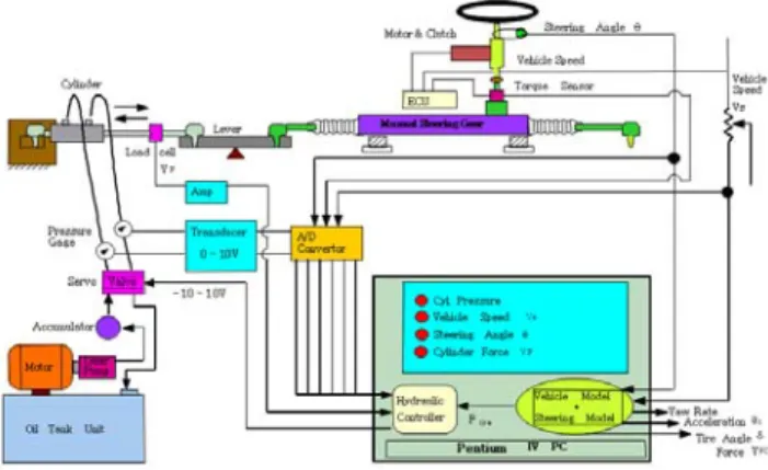
Fig. 1 Composition of HILS system for EPAS
In the development of an EPAS system, numerous real vehicle tests have to be done and data analyzed which can be difficult. Therefore, the use of the HILS system in the development of the EPAS system enables various control algorithms to be applied and/or tuning steering control. Similar real vehicle testing can be repeated and the time and cost of the tests can be reduced using this system.
Applying the HILS system to the EPAS system allows repetitive tests through computer simulations and is as reliable as testing on an actual transporter(Isermann et al., 1999). Fig.1 represents the organization of the HILS system used in this study.
The HILS system user determines the transporter velocity to be used in the experiment. With the input of the speed and steering angle in the HILS system, the lateral force of the tires are calculated to be like an actual transporter and with the calculated force, the hydraulic cylinder is operated which influences the steering force.
The overall organization of the HILS system, as shown in Fig. 1, is made up of the steering wheel, the column, pinion, and rack bar. These are like the actual transporter (Park et al., 2002; Gillespi). The hydraulic system is the controller connected to a computer. The servo valve control signal controls the flux and transfers the force.
The feedback signal to the controller uses loadcell.
The computer based controller receives the input of the steering angle, angle speed, and transporter speed. Based on the 17 free degree model and real vehicle data, the tire lateral force of the behavior of the real vehicle is implemented (Gillespi; Ha, 2006).
The HILS system is made up of the hardware of the steering system and the software for simulation which are from the king pin to the tires of the model transporter.
For simulation, real time transporter dynamic model is created. It should be easy to test the EPAS system and program (Ludger, 1996; Zremba et al., 1995; Adams et al., 2001). To make an accurate dynamic model, the correlation of movement performance, such as load movement, driving comfort, steering, and safety, and the nonlinear characteristics, such as tire and suspension system, have to be considered. Also, various coupling and kinematic modeling have to be considered(Adams et al., 2001). The tire lateral force has to be estimated in real time so the simulation has to be programmed to do so.
Based on multibody dynamics, the appropriate model is chosen so that high performance transporter model is guaranteed(Adams et al., 2001; Allen et al., 1998; Kim et al., 2004).
The model used in our study was based on the model developed at the University of Michigan for the National Highway Traffic Safety Administration (NHTSA) with antilock brake system and active suspension system. All the simulations in this study used the SI unit system.
The inputs of the HILS system used to develop EPAS system were steering angle and transporter velocity. The
inputs of the transporter model were steering angle, brake pressure, transporter velocity, wind velocity, and road conditions. These were used to obtain the lateral force of the tires(Salaani et al., 2002). The HILS system was tested manually on the transporter model to be installed in the system. Based on the extracted values, various parameters were entered as the same as the real vehicle for realistic simulations.
The steering force system was installed in the R transporter for experiments. The real vehicle steering force was measured at 10 km/h, 20 km/h, 30 km/h, 40 km/h, 50 km/h, respectively, at a suspended state. The developed EPAS did not operate over 50 km/h. The common EPAS system was set for more increased force in steering to go over that limit. However, this system was tested manually at 50 km/h and was found to be stable at high speed.
Driver error occurs during manual real vehicle testing so to apply the complete real vehicle operation, the tests have to be repeated numerously to reduce errors. Tests to apply the transporter parameters in the HILS system of Picture 1 have to also be done at the same time.
However, examination of the results of the HILS system show that the steering force calculated from the real vehicle and the tire lateral force produced with the HILS system coincided in the area of interest. Therefore, it can be used in the development and testing of the EPAS system.
Picture 1. HILS System.
The developed electronic steering device of ECU was included in HILS control algorithm was applied to produce the target steering torque with the measurement of steering feel.
3. Electric power assisted steering system
3.1 The electronic control unit (ECU) of electric power assisted steering (EPAS) System
EPAS system is a system to support the steering of the driver using engine power. The EPAS is divided into column type, dual pinion type, single pinion type, and rack type according to the attachment position. The EPAS type depends on the type and configuration of the transporter.
The column type is used in light load transporters while the pinion type and rack type are used in increasing front wheel load transporters(Burton, 2003; Kari et al., 1999).
The R transporter has a hydraulic steering device which was converted into a manual state and the EPAS system was installed. The HILS system was developed to install a column type EPAS in a 1300CC transporter.
However, when considering the weight and the force on the front wheels of the R transporter, there was no optimal EPAS system so an existing EPAS system used in another type transporter was used(Ha, 2006; Camuffo et al., 2002). When car manufacturers develop EPAS systems, the motor and torque sensor options are chosen.
These should be determined with testing of the developed real vehicle test at a manual state. The load on the front wheels and the motor capacity needed for steering force should be considered.
In this paper, an ECU for EPAS was designed, developed, and applied to a transporter to satisfy the steering force needed by the driver. Experiments were focused on evaluating and testing the ECU.
The ECU of the EPAS system has to be able to tune the steering force and when applied to the HILS system and/or real vehicle, needs to be adjusted to the real vehicle.
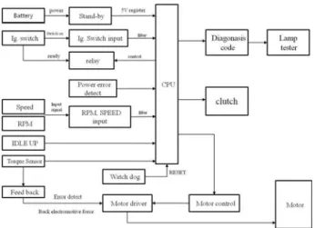
The functions of the ECU include measuring the distortion of the steering wheel and converting the measurements to 8 bit analog-digital converter, pulse width modulation (PWM) output, error detection, and power blockage during malfunction, and converting to manual mode. Each function was developed and tested using the HILS system and evaluated in the real vehicle test. The ECU regulates transporter speed, torque sensor, and the motor of the steering device with the rpm input(Kari et al., 1999; Hassan et al.).
The ECU is induced with ground and 12V batteries.
The induced current is stabilized through noise eliminating
Fig. 2 Schematic diagram of EPAS ECU
coils, the varistor prevents high capacity noise that can occur during transporter drive or the input of surge current from the motor. The varistor is an electronic component with a significant nonlinear current-voltage characteristic and used to absorb part of the surge current. The connected varistor conducts excessive current to prevent malfunction and destruction. Generally, it is used in power input of a transporter.
Table 1 Specification of EPAS ECU power
Voltage Function
12V-battery Transporter battery power 12V-relay Clutch supply power
8V OP-supply power
24V Motor dirver power
5V TTL level power
5V stand-by Error code register power
The types of power used in ECU are shown in Table 1. The 12V transporter battery is always connected to the power and when it is induced consumes under 1mA of current. It is operated by the constantly supplied 12V battery power and ignition switch. After the input of the ignition switch, the ECU processor checks the motor for disconnection. When there are no problems, the relay is operated to induce the 12V relay power. The constantly supplied main power is to operate the EPAS system motor. The 12V relay power is used when there is a problem in the ECU to block the power to the clutch and to drive the EPAS system manually.
The control system made up of sensor inputs and circuits uses OP supply power and is induced with 8V current. The rest of the power supply includes a regulator
with watchdog functions to induce 5V TTL level power.
In the case of the 5V TTL level power, the relay has to work to provide power. When the relay does not work, the power is not induced and so malfunctioning is sensed.
The 5V stand-by power connected to the CPU is induced at below 5% error of 5V TTL level power, when the 5V TTL level power is blocked, to maintain the content of the stand-by RAM. The content of the first 8 byte of the stand-by RAM is maintained in case the power is blocked by the 5V stand-by power. The ECU stores the error code that occurred just before the power outage in the stand-by RAM. When ECU stops operating due to malfunctions, these functions monitor the errors and re-enters the ignition switch and checks the errors before resetting. Error codes are created for the driver’s protection and steering maintenance.
The operation of ignition switch is connected to the ECU so when the ignition is turned on, the ECU automatically operates. However, in the test transporter, the switch is attached on the outside to operate during testing.
The motor control of the EPAS system was stepped up to DC-DC converter with FET voltage to create 24V current and used as FET gate power. The input of the boosting voltage circuit induced 12V power voltage. To verify that DC-DC converter is operating normally, the transistor is connected to the output control to monitor the output of the boosted 24V power on the CPU to prevent malfunction.
The torque sensor operates by the pinion part connected to the sensor shaft and the torsion of the wheel shaft is transferred to the torsion bar. According to the degree of the transfer, the slide above the wheel gear operates and which in turn operates the lever of the potential meter and is input as current value into the ECU.
When operating the steering wheel, torsion occurs from the sensor shaft and the wheel shaft creating torsion on the torsion bar in the column. The sensor shaft groove moves the steel ball, the torque sensor lever moves along the slider operating the potential meter in the torque sensor. This movement is entered in the ECU after the degree and direction of torsion of the transporter axis according to the torsion bar spring constant is converted into voltage.
The torque sensor is made up of a variable resistor that has two different tracks. The induced current is divided by the voltage divider into main sensor output and
servo sensor output (Kari et al., 1999; Guang et al., 2003;
Manu et al., 2003; Hazelden, 2000; Kim et al., 2002).
The main sensor output and servo sensor output are connected to the common current and ground. However, depending on the operation of the spring, the increase of the output is constructed to be opposite.
In the case where the transporter is at a suspended state with no force to the wheel, the main sensor output and the servo sensor output is 2.5V. When the driver applies side to side force to the wheel, the torsion torque of the column is transferred to the sensor which increases the voltage of the main sensor and decreases the servo sensor voltage.
The main sensor output is calculated with the OP amplifier and used in the input of steering system motor control. The output of the servo sensor is converted with the main sensor output and induced in CPU. It is compared with the main sensor output and used when there is an error in the main sensor output due to the torque sensor.
The maximum and minimum output current of the main sensor and servo sensor are fixed. Error is detected when the current goes above or below these values.
The motor drive is made up of H-bridge type and uses N-channel power FET. The FET used in the motor drive is 60V and IDS 45A. The FET signal is induced in the CPU and detects the voltage resistance at the lower part of the drive to control the motor. The malfunction prevention circuit of the ECU consists of a single coil of the motor(Manu et al., 2002; Kim et al., 2002).
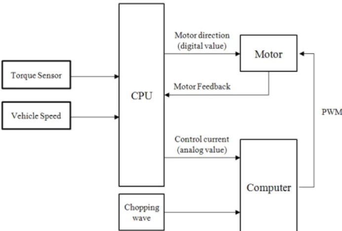
Fig. 3 Block diagram of motor control
The organization of the EPAS motor control system is shown in Fig. 3. The motor control inputs the voltage value of the torque sensor created by the steering force
and the transporter velocity.
Based on the input transporter speed and torque sensor voltage, the CPU is calculated with voltage conversion table of the torque amount needed by the driver and generated by the DAC. To command motor directions, the CPU uses 4 bit digital signals to output direction control signals to operate the FET of the motor drive. 8 bit DAC analog signal uses OP amp to compare with the triangular wave to control the torque in the motor steering support system. Then it is converted to pulse width modulation (PWM) signal to control the motor current for steering.
The current supplied to the motor is converted to the voltage that is resisted at the lower part of the motor drive and fed back to the CPU. The feedback current value, re-input transporter speed, and torque sensor value are used for new current control commands.
The sensors in most transporters are hall sensors on the transmission wheel axle. The wavelength is different for each speed of every transporter and has a 10%
difference with the numbers on display in the gauge.
It is difficult to detect the absolute speed with the speed indicator. And the output of the speed sensor does not coincide with the absolute speed. It is also difficult to drive at a constant speed in the real vehicle test.
However, when using the HILS system, the simulation environment is fixed and test environment is constantly supported so repetitive testing is possible in the same environment.
Analyzing the steering effort of the same steering angle according to the speed, to make the same steering angle more steering effort is needed at high speed. To satisfy the steady steering in any speed, the motor torque has to increase with the increase of speed. However, generally, the heavy feel of steering at high speed is because the transporter can move to the preferred lateral direction in a short time with a small steering angle(Zaremba et al., 1998).
The HILS system used in the EPAS system does not use the motor to support the steering at over 45 km/h to make the steering feel heavy at high speed. When the speed goes over 45 km/h and the steering is not supported with the motor, the driver feels the continuous steering feel. Therefore, at 45 km/h, the driver can control the motor of the EPAS to reduce the steering support to fit the manual steering feel.
The change of the steering force depending on the increase or decrease of speed is generally presented as a hysteresis loop. The manual steering force at 45 km/h
with the increase of speed and the steering force at 35 km/h with the decrease of speed is the same so the starting point of the motor steering support is at 35 km/h and increases the support with the speed.
The transporter RPM signal was used to determine the state of the transporter. The RPM signal wave of the transporter with the EPAS system. In case of sudden change of RPM due to malfunction in the transporter or high RPM during speed reduction, the ECU recognizes these situations as abnormalities in the transporter and stops the EPAS system.
The EPAS system attached to the transporter directly influences the movement so the safety of the driver has to be considered. When abnormality occurs, the driver should be able to operate in manual mode.
During malfunctions or abnormality in the EPAS system, the connection to the electric clutch is disconnected and self diagnosis signal is produced. This is for maintenance convenience and safety precautions. The malfunction part is stored in the memory of the CPU stand bar and the self diagnosis signal is generated. The lamps in the transporter dashboard go out and made into a table or the analog tester can be used for verification(Sanket et al., 2000).
Fig. 4 Simple example of diagnosis code to EPAS
Table 2 Function of diagnosis code to EPAS Code Error function
11 Main sensor error 12 Sub sensor error 13 Main, sub sensor error 21 Over RPM (speed signal ‘0’) 22 Over increase rate of speed signal 41 Motor voltage error
42 Motor control current error 43 Motor current error
44 Electronic clutch error 51 Electronic clutch current error
The self diagnosis signal flickers constantly when the
EPAS system is operating normally. The errors shown in Table 2 are generated as shown in Fig. 4. Pause time is 3 seconds. Numbers in tens are on 1 second and off 0.5 second. Numbers in ones are on 0.5 second and off 0.5 second, with a separation of 2 seconds in between the numbers.
When the EPAS system initiates with the ignition, disconnection and error of the torque sensor and wires are checked. The torque sensor is input for generating the motor current control value and then the error code is verified before continuing. When there are no errors, the self diagnosis signal is generated in 0.5 sec intervals at a 12V pulse.
When the steering wheel is operated by the driver, the tire lateral force created by the road surface friction is transferred through the rack bar and pinion to output axis(Manu et al, 2002).
For safety and convenient control of the ECU, the current control of the steering motor uses driver steering wheel input with a look-up table method based on the transporter speed and torque sensor values(Tim et al., 2002).
During the composition of the look-up table, the support steering force of the EPAS at low speed is high and during high speed, the value is low(Zaremba et al., 1998; Nobuo et al., 1997). During the manual state of the real vehicle test, more steering force was needed at high speed. This was because of reproduction of the real vehicle for HILS system, during handling of the steering wheel at the same angle, more force was required as the speed increased. Various look-up tables were designed and tested three times on the HILS system.
Table 3 Look-up table of turning results in EPAS using HILS system
Velocity
[km/h] 0 10 20 30 40 50
Tuning
objective 0.31 0.28 0.32 0.35 0.38 0.4 1st HILS 1.80 0.50 0.60 0.67 080
2nd 0.13 0.13 0.13 0.13
3rd 0.18 0.19 0.18 0.27 0.25
Test
transporter 0.15 0.16 0.17 0.27 1.70
M/S 0.50 0.60 0.72 0.75
The average speed of the EPAS system was set as shown in Table 3 and the look-up table was tuned
accordingly(Camuffo et al., 2002).
During the first tuning, a similar map for a 600cc transporter was used for testing. In the second tuning, the voltage load of the transporter was not considered in the capacity of the motor. The calculation of the steering force during the suspension was not considered and its value was decided upon through real vehicle test.
Excessive steering force support caused extreme noise and quivering of the steering wheel. Due to the overload of the motor drive, the wheel felt as though force was applied in the opposite direction during the experiment. In the third tuning, the table value was reached. To remove the feel of discontinuity when the support disappears at 45 km/h, the voltage control value of the speed input is changed at 50 km/h.
4. Real vehicle test of EPAS system
4.1 The environment of the real vehicle test The developed EPAS performance and safety was
Table 4 Double power off during the steady state circular run
Class ∙ Class F (First)
Test objective
∙ Power off effect transporter in during driving transporter
∙ Stability during driving transporter error EPAS
∙First test of steering test
Test specification
∙ Radius 50m
∙ Fixed speed rotation driving, test during rotation driving
∙ Speed control : at 10km/h to 60km/h, 10km/h step
∙ Steering angle : constant
∙ 1st power off : at 60km/h, accel pedal off
∙ 2nd power off : at 40km/h, EPAS ECU off
∙ Gear selection : low position (as possible)
∙ Gear position : no change at initial position
∙ Tire tread depth : over 90%
∙ Constant yaw velocity (as possible)
Measuring data
∙ Transporter speed
∙ Steering angle
∙ Lateral acceleration
∙ Longitudinal deceleration
∙ Sampling rate : min. 100 Hz
verified through experiments. The distribution of torque, speed information, and steering frequency were confirmed(ISO 7401; ISO 7975; ISO 3888-1; ISO 3888-2;
ISO 15037; ISO 4138).
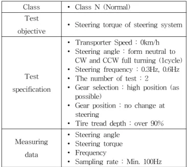
Table 5 Steering torque of steering system (0km/h) Class ∙ Class N (Normal)
Test
objective ∙ Steering torque of steering system
Test specification
∙ Transporter Speed : 0km/h
∙ Steering angle : form neutral to CW and CCW full turning (1cycle)
∙ Steering frequency : 0.3Hz, 0.6Hz
∙ The number of test : 2
∙ Gear selection : high position (as possible)
∙ Gear position : no change at steering
∙ Tire tread depth : over 90%
Measuring data
∙ Steering angle
∙ Steering torque
∙ Frequency
∙ Sampling rate : Min. 100Hz
Table 6 Step input during double lane change Class ∙ Class A (Additional)
Test Objective
∙ EPAS performance as function of sudden steering input during acceleration and deceleration
∙ Response of EPAS during acceleration
∙ Response of EPAS during deceleration
Test specification
∙ Using test track(double lane) of ISO 3888 presentation
∙ From 1 section 1 to section 2 acceleration (40km/h)
∙ Section 2 acceleration
∙ From end of section 2 to section 3 deceleration (0km/h)
∙ Steering angel : driver dependence
∙ Number of test : 1
∙ Gear selection : low position (as possible)
∙ Gear position : no change at steering (as possible)
∙ Tire tread depth : over 90%
Measuring data
∙ Steering angle
∙ Roll angle
∙ Yaw velocity
∙ Lateral acceleration
∙ Longitudinal velocity
∙ Sampling rate : Min. 100Hz
4.1.1 Test standards
Experiments for verifying the performance and safety of the EPAS were double power off during steady state circular run test (Table 4), steering characteristics at suspension state test (Table 5), steering returnability test (Table 6), step input during double lane change test (Table 7), and Slalom test (Table 8), respectively.
Table 7 Steering returnability
Class ∙ Class N (Normal)
Test objective
∙ Stability of EPAS
(steady state cornering, during driving a straight)
∙ Returunablity (steering wheel free release)
Test specification
∙ Radius : 50m
∙ Lateral acceleration and transporter speed set speed
∙ Speed : 10km/h~60km/h (step:10km/h)
∙ Enter straight way (steering wheel free during steady state)
∙ Steering release time : transporter head way enter straight
∙ Time of test : steering release after 5sec
∙ Gear selection : high position (as possible)
∙ Gear position : no change at steering
∙ Braking : no braking during 5sec
∙ Tire tread depth : over 90%
Measuring data
∙ Steering angle
∙ Yaw velocity
∙ Lateral acceleration
∙ Longitudinal velocity
∙ Sampling rate : Min. 100Hz
4.2 Results of the real vehicle test
4.2.1 The developed EPAS system installed real vehicle test
The developed ECU installed R(ECU-R) transporter and another transporter were tested to analyze the characteristics of the ECU. A skilled non-professional driver operated the transporters. ECU-R transporter is the R transporter installed with the developed EPAS, C transporter(Hyundai Click) is a common transporter installed with the EPAS, and the R transporter is the R transporter installed with a hydraulic steering system.
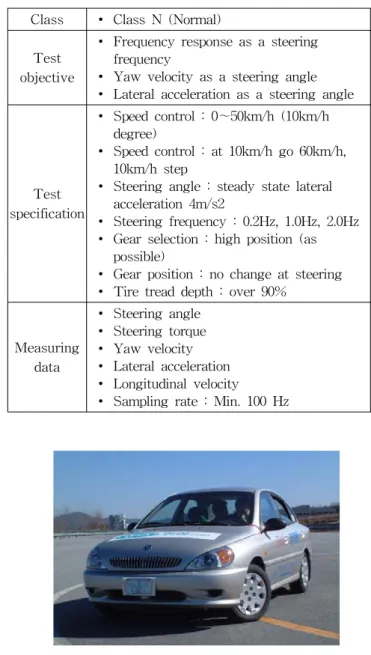
Table 8 Slalom test (continuous sinusoidal steering input) Class ∙ Class N (Normal)
Test objective
∙ Frequency response as a steering frequency
∙ Yaw velocity as a steering angle
∙ Lateral acceleration as a steering angle
Test specification
∙ Speed control : 0~50km/h (10km/h degree)
∙ Speed control : at 10km/h go 60km/h, 10km/h step
∙ Steering angle : steady state lateral acceleration 4m/s2
∙ Steering frequency : 0.2Hz, 1.0Hz, 2.0Hz
∙ Gear selection : high position (as possible)
∙ Gear position : no change at steering
∙ Tire tread depth : over 90%
Measuring data
∙ Steering angle
∙ Steering torque
∙ Yaw velocity
∙ Lateral acceleration
∙ Longitudinal velocity
∙ Sampling rate : Min. 100 Hz
Fig. 5 Test transporter.
KIA Rio in Fig. 5 developed EPAS installed transporter, KIA Rio hydraulic system, and Hyundai Click EPAS installed transporter were used in the test.
Double power off during the steady state circular run (DPO-SSC) test was done by rotating at 50m diameter, the first power off was done at 60 km/h with the acceleration pedal off and the second power off was at 40 km/h with the EPAS ECU off.
Steering returnability (SR) test looked at the stability of the steering wheel after the 50m diameter rotation and the time it took to straighten. Step input during double lane change (SID-DLC) test used ISO 3888 test track.
Suspension state of steering wheel test was done at steering frequency of 0.3Hz and 0.6Hz, steering side to side at neutral state.
Slalom test (Continuous Sinusoidal Steering Input) was done at speeds of 10km/h~ 60km/h, in 10km/h intervals the steering frequencies 0.2Hz, 1.0 Hz, 2.0 Hz. Lateral velocity was 4m/s.
Test real vehicles in the experiments are KIA Rio developed EPAS installed transporter, KIA Rio hydraulic system, and Hyundai Click EPAS installed transporter.
4.2.1.1 Double power off during the steady state circular run (DPO-SSC) real vehicle test
The steering wheel angle reflecting the torque guidance was tested with the double power off during the steady state circular test. The power of the ECU is turned off and the change of torque is measured. Steering wheel angle and torque guidance was observed with the passing of time, the steering angle increased with speed as well as the size of torque. The accuracy of the results is shown in the Fig. 6 and Fig. 7.
Fig. 6 Torque as a steering angle during test of DPO-SSC(10km/h)
Fig. 7 Transporter speed during test of DPO-SSC(10km/h)
4.2.1.2 Steering characteristics(SC) at suspension state test This was the initial test done before the other tests.
This was the safety and credibility test so the test transporter must pass this test before moving on to other tests. Comparison test with a different transporter was not needed in this test(ISO 3888-2; ISO 7975; Tahami et al.,
2003; Wade Allen et al., 2001).
This test was to analyze the torque performance of the developed EPAS system. The R transporter and C transporter were compared to figure out the size and characteristics of the assistance force of the developed system. The torque was unrelated to the steering angle in the R transporter while the torque changed depending on the steering angle in the C transporter. The R transporter is provided with assistance force from the consistent hydraulic so it has consistent and safe steering torque.
However, the EPAS system uses an electric motor, the size of the assistance force differs depending on the load of the motor. The motor capacity of the C transporter is bigger than that of the developed EPAS so the assistance force is bigger in the C transporter than the R transporter. Therefore, the results of the C transporter can be analyzed to improve the developed system(Data, 200).
Fig. 8 Comparison of torque as a time during test of SC
Fig. 8 shows the graph of the handling torque at a suspended state (0 km/h). This was used to analyze the size of the assistance force of the ECU. The off state and on state of the ECU were compared as shown in Fig. 8.
The size of torque was about 70Nm bigger at the off state compared to the on state which was due to the size of the assistance force of the electric motor. When compared with the common system, the steering torque was similar while the developed EPAS system torque was 200~300% bigger.
4.2.1.3 Step input during double lane change (SID-DLC) test
The input of the steering wheel during acceleration and reduction of speed was used to analyze the characteristics of the EPAS. The responses of the EPAS during lane change at high speed and at low speed were analyzed in Fig. 9~12.
The characteristic of the steering system is analyzed
with the input of the steering during lane change.
Compared with the common system, the size of the steering torque was about 20% bigger.
Fig. 9 Comparison of torque as a steering angle during test of SID-DLC
Fig. 10 Comparison of transporter velocity as a time during test of SID-DLC
Fig. 11 Comparison of torque as a time during test of SID-DLC
Fig. 12 Comparison of steering angle as a time during test of SID-DLC
Fig. 13 Comparison of torque as a steering angle during test of SR (20km/h)
Fig. 14 Comparison of torque as a time during test of SR (20km/h)
Fig. 15 Comparition of steering angle as a time during test of SR (20km/h)
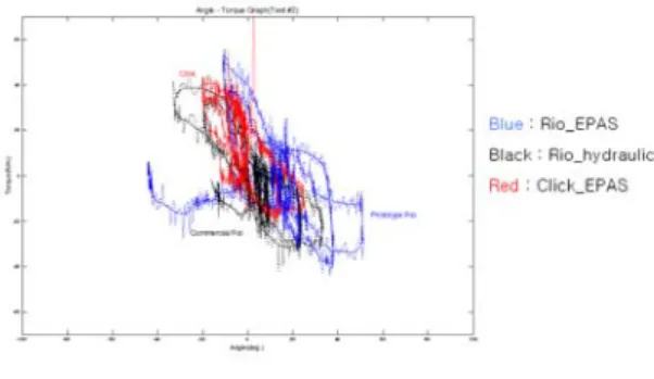
Fig. 16 Comparison of torque as a steering angle during slalom test(0.2Hz, 20km/h)
4.2.1.4 Steering returnability(SR) Test
This test is to analyze the restoring ability of the
transporter during rotation. The size of the torque differs greatly depending on the transporter speed. The size of the restoring force is proportional to the torque(Data, 2002;
Norman, 1984).
The steering returnability is associated with the steering sensation felt by the driver. The EPAS and hydraulic steering system have different characteristics so the steering feel cannot be accurately compared(Wade Allen et al., 2001; Data, 2002; Masahiko et al., 2000). In the case of the EPAS, structurally the motor is connected to the gear so the steering returnability is overall poorer than the hydraulic system. In the developed EPAS transporter, the restoring force of the wheel was produced at over 20 km/h in Fig. 13~15. The results in Fig. 14 show the handling torque of the Rio transporter with the hydraulics system rapidly reduces due to restoring force.
The handling torque of the currently available Click EPAS on the market also reduces due to restoring force but does not completely disappear. The developed Rio-EPAS of our lab also reduces the steering wheel torque but considerable amount of residual torque exists.
The hydraulic system of the Rio transporter tends to make the residual torque 0, as shown in Fig.15. The residual torque of the Click-EPAS minutely exists. The restoring force appears in the developed Rio-EPAS but residual torque exists considerably.
When compared with the common system, the assistance force effects less than the common system so the speed is higher to produce restoring force of the wheel. Comparing the numbers at the transporter speed, the steering returnability at 40 km/h of the developed EPAS transporter is similar to the R transporter at 30 km/h.
4.2.1.5 Slalom Test (Continuous Sinusoidal Steering Input Test)
This test is the most important in comprehending the characteristics of the developed EPAS transporter. This test analyzes the torque characteristic of the wheel when operating side to side. Speed and steering torque are proportional as well as the steering speed and the steering torque. The test results in Fig. 16 show that the driver moved in one direction and the exact speed cannot be realized during the test. However, the characteristic of the system can be identified.
Three tests were done according to the steering frequency. The steering torque results at 0.2 Hz, 1 Hz, and 2 Hz, respectively, show that the faster the frequency,
the bigger the torque became. The developed EPAS system’s steering torque was 20% larger than the common system’s.
Tests were done on the R transporter, ECU-R transporter, and C transporter at 10 km/h, 20 km/h, 30 km/h, 40 km/h, 50 km/h, and 60 km/h, respectively, steering at 0.2 Hz, 1 Hz, and 2 Hz, respectively. Fig. 16 shows the steering characteristic of each transporter at 20 km/h with a steering frequency of 0.2 Hz.
The real vehicle test results at 20 km/h show that in the ECU-R transporter, torque is stuck suddenly at 30˚~
45˚ steering angle but from the other data this is considered to be caused by the driver’s driving habit. The C transporter measured the smallest steering force, thus the power needed for steering is small and in the hydraulic system, the restoring of the wheel vibration and steering angle show the most stable value. The steering force of the ECU-R transporter reflects the other transporters and operated without any malfunctions during the test.
The steering characteristics according to the speed 2km/h at the same frequency 0.2Hz are shown in Fig. 16, the steering characteristics of the transporters at 20 km/h at steering frequency 0.2 Hz. The developed EPAS produced noise and vibration overall especially, when turning from the right direction to the left. This is thought to be due to driving error. This was observed in the hydraulic system and the common system as well with the increase of speed.
When comparing the hydraulic system and the common EPAS system, the common EPAS system showed even steering force overall while the hydraulic system showed sudden steering force requirement.
The results show that vibration did occur, however, in the EPAS system steady increase of the steering force was observed as well as support of the steering force even after its limit. While in the hydraulic system, the steering force suddenly increased according to speed after which support was given.
The overall test transporters showed unsatisfactory steering guidance. Especially, when steering right from the left direction, there was noise in the steering force.
Almost all the experiments had this noise so it was thought to be the result of the driver or error in calculations. The data was verified with the lower part of the steering guidance as the standard. In the developed EPAS system, it was lacking compared with the hydraulic system and the common EPAS system and did not have
steady increase value. The hydraulic system was also found to be inconsistent compared with the common EPAS system.
The common EPAS system showed the most outstanding characteristic in sudden steering and high steering frequency. The feel of the transporter during the tests was similar in all the transporters. The developed EPAS was found to be lacking in the steering response.
This was due to the disconnection of the steering support at 45 km/h so the driver would not feel the resistance during the control of the steering force. This can be controlled in the development of the EPAS with some tuning.
5. Conclusion
In the development of EPAS, the HILS system is used to reduce the cost and time. In the organization of the HILS system, the hardware part was made up of the steering wheel to the pinion and rack bar. The inputs of speed and steering angle were used on a 17 degree-of-freedom transporter model to reproduce the tire lateral force. The reproduced tire lateral force was analyzed with real vehicle tests.
The developed EPAS was made with existing products and electric controlled devices. The EPAS received the desired speed and steering force then the motor is operated to follow the commands. Also, safety precautions, such as self diagnosis, were installed in the real vehicle in case of malfunction.
The EPAS was not mechanically developed for the transporter so the degree of steering force and steering feel had to be adjusted through control of the ECU.
The developed EPAS was installed in the HILS system and applied to the already constituting control algorithm so that the desired steering force can be reproduced and also for the calculation of the steering sensitivity to set in the test. Also, the developed ECU of the EPAS was used to reproduce hard to find malfunctions of the EPAS in real vehicle tests to verify the malfunctions. Then the developed EPAS was installed in a real vehicle and its performance was tested and analyzed.
The benefits of using a HILS system in the development of the EPAS were confirmed and used to develop a usable EPAS in a real vehicle. In cases when malfunctions are detected, the electric clutch is disconnected and the motor power is cut off and converted to manual mode. However, the EPAS on the
market today does not use electric clutches and handle malfunctions. EPAS with clutches has compact transporter motor capacities which are not enough to support power and are insufficient in assisting the steering force. Due to insufficient motor power, excessive motor control is needed which in turn causes excessive noise and vibration. It is difficult to produce satisfying steering sensitivity using an 8 bit CPU in motor control.
Transporter installment should be considered in the selection of the motor and with real vehicle tests the function of the CPU should be improved so that it can be reproduced in the HILS system then an EPAS without an electric clutch can be developed.
The development of current transporters considers convenience, pollution, and efficiency which have lead to the production of hybrid transporters and electric transporters. Therefore, the need for electric power assisted steering systems is increasing.
The developed electronic steering device of ECU was then installed in an actual transporter for performance evaluation and analysis.
The EPAS system in this paper was used in the development of an EPAS and its benefits were confirmed and an EPAS system for application in an actual transporter was developed.
References
[1] Adams W. Keith and Richard W. Topping(2001), “The steering characterizing functions (SCFs) and their use in steering system specification, simulation, and synthesis,” SAE Paper 2001-01-1353.
[2] Anthony W. Burton(2003), “Innovation drivers for electric power-assisted steering,” IEEE Control Systems Magazine, pp. 33-39.
[3] Camuffo. I., Caviasso. G., Pascali. L., Pesce. M., Alviano. E.(2002), “Simulation tools and evaluation criteria for steering wheel feel improvement of an electric power steering system,” SAE Paper 2002-01-1593.
[4] Choi, G. J., Lee, K. H., Yoo, Y. M.(1995), “Development of a real-time transporter dynamic simulation software,” SAE Paper No. 953763.
[5] Data S. C.(2002), “Objective evaluation of handling quality,” Proc. Instn. Mech. Engr., Vol. 216, Part D: J.
Automobile Engineering.
[6] Guang Liu, Alex Kurnia, Ronan De Larminat, Sanford Jay Rotter(2003), “Position sensor error analysis for
![Table 3 Look-up table of turning results in EPAS using HILS system Velocity [km/h] 0 10 20 30 40 50 Tuning objective 0.31 0.28 0.32 0.35 0.38 0.4 1st HILS 1.80 0.50 0.60 0.67 080 2nd 0.13 0.13 0.13 0.13 3rd 0.18 0.19 0.18 0.27 0.25 Test transp](https://thumb-ap.123doks.com/thumbv2/123dokinfo/5192078.351298/6.892.74.445.839.1100/table-look-turning-results-velocity-tuning-objective-transp.webp)