대 한 방 사 선 의 학 회 지 1993; 29(2) : 187~192
Journal 01 Korean Radiological Society, March, 1993
MRI상 악관절원판의 정상위치
한림대학교 의과대학 방사선과학교실
이 열·박기순·정수영·배상훈 - Abstract-
A Study on the Normal Position of Articular Disk of the Temporomandibular J oint on MRI
Yul Lee
,
M.D.,
Ki Soon Park,
M.D.,
Soo Young Chung,
M.D.,
Sang Hoon Bae,
M.D.Depaγtment 01 Radiology, College 01 Medicine, Hallym Uψversity
To evaluate the normal range of articular disk postion, MRIs of 25 temporomandibular joints πM]s) in 19 asymptomatic volunteers were analysed. On the closed mouth sagittal Tl weighted MRI the junction of the posterior band and bilaminar zone was within 100 anterior from the vertical line through the apex of condylar head in 19 (76%) and within 200 in 23 (92%) TM]s. The intermediate zone of the articular disk was located between the posterior surface of articular eminence and the anterior surface of condylar head in 22 (88%) TM]s.
We suggest that on the closed mouth sagittal MRI the junction of the posterior band and the bilaminar zone could be within 100 anterior from the vertical line through the apex of condylar head in asymptomatic Korean persons. If the junction is located more than 200 anterior from the vertical line or the intermediate zone is anterior to the anterior surface of condylar head it is suggested that the disk is anteriorly displaced.
Further studies are needed to evaluate the clinical significance of mild anterior displacement of the articular disk (11 0 -20 0) in asymptomatic persons.
Index Wosrds: ] aws
]oints, Temporomandibular 244
]oints, Temporomandibular, MR studies 244.1214
서 론
MRI는 1980년대 말부터 악관절조영술을 대신하여 악 관절질환의 진단에 있어서 가장 유용한 검사방법으로 정 착되고 있다(1). 기왕의 보고들에 따르면 관절원판
(articular disk)의 후방대 (posterior band) 가 폐구상태
의 시상면영상에서 관절구두(condylar head)의 직상부,
즉 12시 방향에 위치하는 것이 정상이며 이것이 악관절내 부장애의 진단에 가장 중요한 관절원판의 전방전위의 여 부를 판별하는 일반적인 기준으로 알려져 왔다(1-4). 그
러나 최근의 일부 보고에 의하면 악관절부위의 증상이 없 는 정상인에서도 폐구상태에서 후방대가 관절구두의 직상 부보다 어느정도 전방에 위치할 수도 있다고 하며 (5-7) 아직까지 관절원판의 정상적인 위치에 관한 명확한 기준 이 정립되어있지 않은 실정이다.
저자들은 악관절부위의 증상이 없었던 25예의 MRI를 대상으로 한국인에 있어서의 관절원판의 정상 위치를 알 아보기 위하여 본 연구를 시행하였다.
이 논문은 1992 년 7월 27 일 접수하여 1993 년 1 월 8 일에 채택되었음.
- 187-
대한방사선의학회지 1993; 29(2) : 187~192
대상 및 방법
대 상
악관절부위의 통증, 클릭음, 운동장애와 같은 악관절질 환의 증상이 없는 21명을 대상으로 악관절 MRI를 시행 하였다. 이들은 모두 다른 원인으로 뇌의 MRI를 시행하 는 환자들이 었으며, 뇌 의 MRI가 끝난후 악관절 MRI를 추가로 시행하였다. 21명중 7명에서는 양측의 악관절,
14명에서는 일측의 악관절에 대해 MRI를 시행하여 얻은 28예의 악관절 MRI중 해상력이 부족하여 관절원판이 잘 보이지 않았던 3예를 제외한 25예(19명)를 대상으로 하 였다. 19명중 남자가 12명, 여자가 7명 이었으며 12세에 서 71세까지로 평균연령은 30세였다.
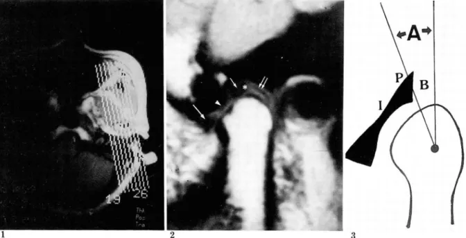
다. 먼저 시상연영상을 위한 악관절의 경사각을 알기 위 하여 스핀에코 방법으로 악관절부위의 횡단면 Tl강조영 상 을 얻 었 다(TR/TE=200/15 msec, number of ex- citation= 1, matrix number= 256x 256, slice thick- ness= 5mm, scan time= about 54 sec) (Fig. 1)
위에서 얻은 횡단면영상에서 보이는 관절구두의 장축에 수직이 되도록 기울인 각도로 직경 9cm인 표면코일을 이 용하여 폐구상태에서 스핀에코 방법으로 악관절부위의 시 상 연 Tl 강 조 영 상 을 얻 었 다(TR/TE= 700/20 msec, number of excitation= 2, matrix number= 192X 256, slice thickness= 3mm, scan time= about 4min 32 sec) (Fig. 2).
관절원판 위치의 계측방법
먼저 관절원판이 가장 잘 보이는 단면에서 관절원판의 후방대를 확인하고 Drace 등(5)의 계측방법에 의거하여
악관절 MRI 방법 후방대 와 bilaminar zone의 경 계 부위 를 지 정 한후 관절
MRI 는 Siemens 사의 Magnetom 1. 5T 를 사용하였 구두의 정점에서 수직선을 긋고 이 수직선과 전술한 후방
Fig. 1. T1 weighted axiallocalizing image. Section through the condylar head level.
The oblique Iines indicate the sagittal image orientation of the TMJ.
Fig. 2. MRI of asymptomatic TM
J.
Sagittal Tl-weighted image in closed-mouth position. Articular disk is ap- peared as a low signal bow-tie shaped structure. Anterior band (long aπow) , intermediate zone (arrowhead), posterior band (short arrow) and bilaminar zone (double arrows) are indicated. Asterisk indicates the junction between posterior band and bilaminar zone. Posterior band angle is about 50.Fig. 3. Diagram of measuring the posterior band angle.
After identifying the junction of the posterior band and bil때꾀nar zone, a line is drawn from this junction to the estimated center of condylar head curvature. Posterior band angle (A) represents the angle between this line and the verticalline through the apex of condylar head. B=bilaminar zone, P=posterior band of articular disk, 1 = intermediate zone of articular disk.
이 열 외 : MRI상 악관절원판의 정상위치
대와 bi!aminar zone의 경계부위가 이루는 각도(이하 각각 170, 220, 25。 였던 3예(1 2%) 에서는 관절구두의 전 후방대각 posterior band ang!e- 이라고 약함)를 각도 사면보다 전방에 위치하였다 (Fig.5).
기로 측정하였다. 측정시 각도기의 중심은 관절구두의 악 관절면이 이루는 곡면의 중심에 두었으며 동일한 방법으 로 3회 측정한 후 이의 평균치를 각각의 후방대각으로 정 하였다 (Fig.3). 또한 관절원판의 intermediate zone이 관절결절 (articu!ar eminence) 과 관절구두 사이의 어느 부위에 위치하는 지를 관찰하였다.
?킥 <= 과
총 25예의 악관절 MRI에서 후방대각은 7。에서 25。까 지로 평균 6.80, 표준편차 7。였다. 0。에서 5。사이가 10예 (40%) 로 가장 많았고 10。 이하가 19예로 전체의 76%를 차지하였으며, 2예 (8%)에서는 20。를 넘는 후방대각을 나 타내었다(Tab!e 1) (Fig. 4) 양측 악관절의 MRI가 시행 되었던 7예 모두에서 1。에서 5 。까지 양측의 후방대각이 서로 다르게 측정되었다.
관절원판의 intermediate zone 은 25예중 22예(88%) 에서 관절결절의 후사연(posterior s!ope)과 관절구두의
고 "'~ E크
악관절질환의 유병율은 확실히 밝혀지지는 않았으나 외 국의 한 통계에 의하면 성인의 약 28%가 악관절부위의 증상을 호소할 정도로 흔한 질환이다(8-10). 특히 남,녀 의 비율이 약 1:5-6정도로 여자에게 많으며 왕성한 활
Table 1. Posterior Band Angle of 25 Asympto-matic TMJs.
Posterior Band Angle
n
Be10w 0 0- 5 6-10 11-15 16-20 21-25 Total
No.of Cases (%) 3 ( 12) 10 ( 40) 6 ( 24) 2 ( 8) 2 ( 8) 2 ( 8)
25 (100)
전사면(anterior s!ope) 사이에 위치하였고 후방대각이 TMJs: Temporomandibular joints
4a 4b 5
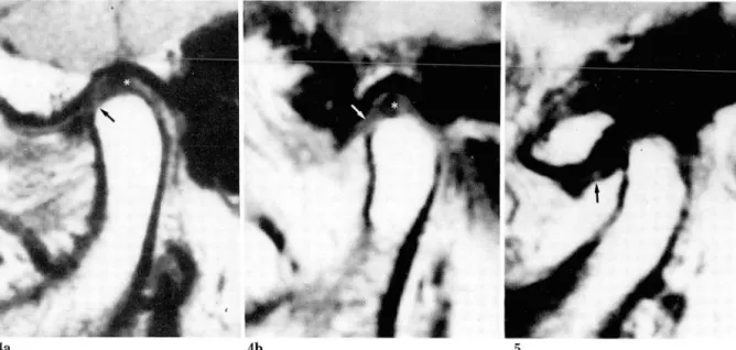
Fig.4. MRIs of asymptomatic TMJs. Sagittai Tl-weighted images in closed-mouth position. Asterisk indicates the junction between posterior band and bilaminar zone. Posterior band angle is about 50 (a) and 100
(b). The intermediate zone (arrow) of the articular disk lies between the posterior surface of articular eminence and the anterior surface of cond끼ar head in both cases.
Fig. 5. MRI of asymptomatic TM
J.
Sagittal Tl-weighted image in closed-mouth position. Posterior band angle is about 250. The intermediate zone (arrow) of the articular disk lies anterior to the anterior surface of condy- lar head.
- 189-
대한방사선의학회지 1993; 29(2) : 187~192
6a 6b 7
Fig. 6. MRIs of TMJ s with internal derangement. Sagittal T1-weighted images in closed -mouth position. Pos- terior band angle is about 350 (a) and 800 (b). Arrow: articular disk.
Fig. 7. MRI of asymptoma디c TM
J.
Sagittal T1-weighted image in closed-mouth position. The junction be- tween the posterior band and the bilaminar zone is not cle외y defined. But the intermediate zone (arrow) of the articular disk lies between the posterior surface of articular eminence and the anterior surface of coudylar head.동기인 20-40대의 젊은 연령층에 호발하는 것으로 알려 져 있다 (9, 10).
MRI 는 악관절조영술과는 달리 비침습적이고 어려운 기술을 요하지 않으면서도 관절원판은 물론 근육, 골 등 관절 주위의 구조물들을 직접 나타내줄 수 있기 때문에 최근에는 악관절질환의 진단에 있어서 가장 유용한 검사 방법으로 정착되고 있다(1 -3) . 국내에서도 악관절 MRI 에 관한 관심이 점차 증가하고 있으나 아직까지 이에 관 한 보고는 찾아보기 힘든 실정이다.
악관절의 내부장애란 악관절의 정상적인 움직임에 장애 를 가져오는 모든 경우를 통틀어서 칭하는 말이다(1). 이 것의 가장 흔한 원인은 관절원판의 전위이며 실제로 관절 원판의 전위와 악관절 내부장애의 두가지 용어가 서로 구 별이 없이 사용되어지기도한다(1-3). 관절원판의 전위는 거의 대부분 전방 혹은 전내측 방향으로 일어나며 따라서 관절원판의 전방으로의 전위 여부를 판별하는 것이 악관 절 내부장애의 진단에 가장 중요한 요체가 되고있다 (1-3).
관절원판은 후방대가 관절구두의 직상부, 즉 12시 방향 에 위치하는 것이 정상적인 위치이며 이것이 관절원판의 전방전위의 여부를 결정하는 일반적인 기준으로 알려져 왔으나 MRI의 이용이 보편화 되면서 점차 이 기준에 대
한 의문이 제기되고 있다(5 끼. Kircos 등(6)은 악관절 부위의 증상이 없었던 42예의 MRI상 13예 (32%)에서 관 절원판의 전방전위를 관찰하였고 Drace 등 (5) 은 악관절 부위의 증상이 없는 30예의 정상 자원자의 MRI상 관절 원판의 후방대와 bilaminar zone의 경계부위가 폐구상 태에서 관절구두의 직상부보다 10。까지 전방에 위치할 수 있다고 보고하였다. 저자들도 Drace 퉁이 사용한 방법을 이용하여 관절원판의 후방대의 위치를 측정하였는데 측정 과정상 몇 가지의 문제점이 있는 것이 사실이다. 우선 관 절원판 특히 후방대가 잘 구별되지 않는 경우인데 본 연 구에서도 3예가 이러한 원인으로 인해 대상에서 제외되었 다. 연 구 대 상 에 포 함 되 었 던 25예 에 서 도 후 방 대 와 bilaminar zone의 경 계 부위 를 정 확히 어 느 점 으로 지 정 하느냐에 따라 후방대각의 측정치가 달라질 수 있다. 또 관절구두의 악관절면이 균일하지 않은 경우 각도기의 중 심을 어디에 두느냐에 따라서도 측정치가 달라질 수 있을 것이다. 측정의 오차를 줄이기 위해 통일한 악관절에서 3 회 측정한 평균치를 각각의 후방대각으로 하였지만 매회 의 측정시 00 -5。 정도의 차이가 났던 만큼 5。 이내의 차 이는 큰 의미가 없을 것으로 생각된다.
본 연구의 결과에서 총 25예의 악관절 MRI 상 23예 (92%)에서 후방대각이 20。 이하였다. 평균이 6.80, 표준
편차가 7。 였으므로 정규분포를 가정하더라도 95 per- centile (2 standard deviation)은 7. 2 。 에 서 20.8。가 된다. 따라서 한국인에 있어서 MRI상 관절원판의 후방 대와 bilaminar zone의 경계부위가 폐구상태에서 관절 구두의 직상부보다 20。이상 전방에 위치하는 경우에는 관 절원판이 전방으로 전위된 것으로 간주하여도 큰 무리는 없을 것으로 생각된다(Fig.6) 또 25예중 19예(76%)에 서 후방대 각이 10。 이하였던 것을 감안하면 후방대와
bilaminar zone의 경계부위가 관절구두의 직상부보다 약 10。정도까지 전방에 위치하는 것은 정상범위로 볼 수 있을 것으로 생각된다. 문제는 11 0 -20。 정도의 후방대각 을 보였던 4예인데 이들도 정상범위이거나 혹은 경한 정 도로 관절원판이 전방전위되었을 두가지 가능성을 모두 생각해 볼 수 있다. Shannon 등(8)은 증상이 없는 10명
(20 악관절)의 정상 자원자를 대상으로 MRI를 시행한 결과 관절원판의 후방대가 관절구두의 직상부(1 2시 방향) 에 위치했던 경우는 10예의 악관절(50%)에 불과하였고 5예에서는 11시 방향, 4예에서는 10 방향에 위치하였던 것을 관찰하였다. 또 정상 자원자 30명을 대상으로 한
Drace 등(5)의 보고에서도 평균 후방대각은 5。 정도 였 지만 악관절부위의 외상이나 치열교정술과 같은 과거력이 있 는 경 우 에 는 평 균 후 방 대 각 이 16。 였 다 고 한 다.
Conway 등(11)은 경한 정도로 관절원판이 전방전위 되 었을 때 이것이 정상범위인지 혹은 병적인 전방전위인지 를 구별하는 데 에는 악관절의 동적 인 정보(dynamic information)가 중요하다고 하였다. 일반적으로 MRI는 악관절조영술에 비해 악관절의 동적인 정보를 얻기 힘들 다는 것이 단점으로 지적되고 있으나 최근 여러가지 방법 의 고속 MRI를 이용하여 이러한 단점을 극복하려는 노 력이 진행되고 있다(11, 12). 이와같이 악관절질환의 증 상이 없으면서 경한 정도의 관절원판의 전방전위를 보이 는 경우에 대한 임상적인 의의는 아직 확실히 밝혀지지 않았으며 추적검사 등을 통해 앞으로 계속 연구되어야 할 과제로 생각된다(13).
일반적으로 폐구상태의 MRI에서는 저신호강도로 나타 나는 관절결절과 관절구두의 관절연 사이 에서 눌려 진 관 절원판의 후방대가 bilaminar zone 과 잘 구별이 되지 않을 수가 있기 때문에 개구상태에서 스캔하는 것이 관절 원판의 형태를 관찰하는 데에는 더좋다고 한다(14). 또 관절원판의 MRI 신호강도에 관한 최근의 보고에 의하면 (15) T1 강조영상에서 후방대 내에 정상적으로도 고신호 강도가 보일 수 있으며 따라서 상대적으로 저신호강도로 나타나는 후방대 의 상, 하면이 bilaminar zone으로 오인 되어 마치 후방대가 앞쪽으로 전위된 것처럼 잘못 판단할
이 열 외 : MRI 상 악관절원판의 정상위치
수 있으므로 주의를 요한다고 한다. 이와같이 관절원판의 후방대 가 잘 보이 지 않거 나 후방대 와 bilaminar zone의 경계가 분명하지 않는 경우에는 관절원판의 intermedi- ate zone이 관절결절과 관절구두 사이의 어느 곳에 위치 하는 가를 관찰하는 것이 도움이 되지 않을까 생각된다
(Fig.7). 본 연구의 결과에서 총 25예중 22예(88%)에서
intermediate zone이 관절결절의 후사면과 관절구두의 전사면 사이에 위치하였고 나머지 3예(12%)에서는 intermediate zone 이 관절구두의 전사면 보다 전방에 위치하였는데 이들 3예의 후방대각은 모두 17。 이상이었 다(Fig.4b). 해부학적으로도 폐구상태에서 악관절의 진 정한 관절면(weight bearing portion)은 관절결절의 후 사면과 관절구두의 전사면이며 이 사이에 관절원판의 intermediate zone이 위치하는 것으로 알려져 있다(13,
14,16). 따라서 intermediate zone 이 관절구두의 전사 면보다 전방에 위치하는 경우도 관절원판의 전방전위로 판단해야 할 것으로 생각되며 후방대각 100 -20。 정도의 경한 전방전위의 의미를 파악하는 데에도 intermediate
zone의 관찰이 도움이 될 것으로 생각된다.
결론적으로 악관절 부위의 증상이 없는 한국인에 있어 서 관절원판의 후방대와 bilaminar zone의 경계부위는 폐구상태의 시상연 MRI상 관절구두의 직상부보다 10。 정도까지 전방에 위치할 수 있으며 20。 이상이거나 관절 원판의 intermediate zone이 관절구두의 전사면보다 전 방에 위치할.경우 관절원판의 전방전위로 간주해야 할 것 으로 사료된다. 10。에서 20。 사이는 경계치 내지 경한 정 도의 전방전위로 생각되는데 이에대한 임상적 의의는 향 후 더 연구되어야 할 것이다.
참고문헌
1. Nance EP, Posers TA. Imaging of the temporomandibular
1990;
28:1019-1031joi따
2. Katzberg RW. Temporomandibular joint imag- ing. Radiology 1989; 170:297-307
3. Kaplan PA, Helms CA. Current status of temporomandibular joint imaging for the diag- nosis of internal derangement. AJR 1989; 152:
697-705
4. Westesson PL, Katzberg RW, Tallents RH, Sanchez-Woodworth RE, Svensson SA, Espeland MA. Temporomandibular joint: Comparison of MR images with cryosec-tion외 anatomy. Radiolo-
- 191 -
대한방사선의학회지 1993; 29(2) : 187~192
gy 1987; 164:59-64
5. Drace JE, Enzmann DR. Defining the normal temporomandibular joint: Closed, parti허ly open and open-mouth MR imaging of asymptomatic subjects. Radiology 1990; 177:67-71
6. Kircos LT, Ortendahl DA, Mark AS, Arakawa M Demonstration of TMJ anterior disc position by MR in asymptomatic volunteers, J Oral Maxillofac Surg 1987; 45:852-854
7. Kaplan P A. Computed tomography vs.
arthrography in the evaluation of the
temporomandib버ar joint. Radiology 1984; 152: 825-827
8. Shannon M, Pa1acios E, Va1vassori GE, Reed CF.
MR of the normal temporomandibular joint. In Palacios E, Va1vassori GE, Shannon M, Reed CF.
Magnetic resonance of the temporomandibular joint. New York: Thieme 1990; 54-56
9. Gurlnick W, Kaban LB, Merrill RG.
Temporomandib비ar joint afflictions. N Engl J Med 1978; 299:123-129
10. Solberg WK, Woo MW, Houston JB. Preva1ence of mandibular dysfunction in young adult. J Am Dent Assoc 1979; 98:25-34
11. Conway WF, Hayes CW, Campbell RL.
Temporomandib버 ar joint motion: efficacy of fast low-angle shot MR imaging. Radiology 1989; 172:821-826
12. Burnett KR, Davis CL, Read
J.
Dynamic dysplay of the temporomandibular joint meniscus by using “fast-scan" MR imang-ing. AJR 1987;149:959-962
13. Kircos LT, Ortendahl DA. Mangetic resonance imaging of the temporomadibu-lar joint. In:
Delbalso, Maxi!lofacial imaging. Philadelphia: W.
B. Saunders. Co. 1990; 681-683
14. Helms CA, Kaban LB, McNeill C, Dodson T Temporomandibular joint: Morphology and sig- nal intensity characteristics of the disk at MR im- aging. Radiology 1989; 172:817-820
15. Drace JE, Young SW, Enzmann DR. TMJ menis- cus and bilaminar zone: MR imaging of the structure-diagnostic landmarks and pit셈ls of in- terpretation. Radiology 1990; 177:73-76 16. Sarnat BG, Laskin DM. The temporoman-dibular
joint: A biologic basis for clini때 practice, 3rd ed. Springfield: Charles C Thomas Pub. 1979;
85-113
- 192-