P
olymethylmethacrylate(PMMA) is the materi- al of choice for the construction of complete dentures.Although denture base resins are not ideal in every respect, the combination of properties such as work- ing characteristics, minimum expense, excellent esthetics, accuracy of fit and stability in the oral
environment is suitable. Mechanical failure of acrylic dentures during services still occurs, however.1-3 Breakage may result from impact fracture, for example on dropping the denture during cleansing, or from fatigue fracture; this is often seen in complete upper dentures, where continual flexing of the base during function leads to crack development.
EFFECTS OF CHOPPED GLASS FIBER ON THE STRENGTH OF HEAT-CURED PMMA RESIN
Sang-Il Lee, D.D.S., Chang-Whe Kim, D.D.S., M.S.D., Ph.D., Yung-Soo Kim, D.D.S., M.S.D., Ph.D., M.Sc.(O.S.U.)
Department of Prosthodontics, Graduate School, Seoul National University
The fracture of acrylic resin dentures remains an unsolved problem. Therefore, many investigations have been performed and various approaches to strengthening acrylic resin, for example, the re- inforcement of heat-cured PMMA resin using glass fibers, have been suggested over the years. The aim of the present study was to investigate the effect of short glass fibers treated with silane cou- pling agent on the transverse strength of heat-polymerized PMMA denture base resin. To avoid fiber bunching and achieve even fiber distribution, glass fiber bundles were mixed with PMMA pow- der in conventional mixer whose blade was modified to be blunt. Composite of glass fiber(11
μ
m di-ameter, 3mm & 6mm length, silane treated) and PMMA resin was made. Transverse strength and Young’s modulus were estimated. Glass fibers were incorporated with 1%, 3%, 6% and 9% by weight.
Plasticity and workability of dough was evaluated. Fracture surface of specimens was investigated by SEM.
The results of this study were as follows
1. 6% and 9% incorporation of 3mm glass fibers in the PMMA resin enhanced the transverse strength of the test specimens(p<0.05).
2. 6% incorporation of 6mm glass fibers in the PMMA resin increased transverse strength, but 9%
incorporation of it decreased transverse strength(p<0.05).
3. When more than 3% of 3mm glass fibers and more than 6% of 6mm glass fibers were incorporated, Young’s modulus increased significantly(p<0.05).
4. Workability decreased gradually as the percentage of the fibers increased.
5. Workability decreased gradually as the length of the fibers increased.
6. In SEM and LM, there was no bunching of fibers and no shortening of fibers.
Key Words
Glass fiber, PMMA resin, Transverse strength, Mixing method.
J Korean Acad Prosthodont : Volume 39, Number 6, 2001
Much attention has been directed toward the rein- forcement of acrylic resins to enhance their physical and mechanical properties. It has been reported that carbon fibers improve the fatigue and tensile strength, transverse deflection, and modulus of elasticity of PMMA resins. However, carbon fibers may cause an esthetic problem because of the black color of the fibers.4-6,9,10Inclusion of metal fillers improves the thermal conductivity of PMMA and enhances its strength, but also contributes to poor esthetics for complete dentures.11Aramid fibers have been shown to significantly increase the impact strength of PMMA resin and enhance the fracture resistance of acrylic resin denture base materi- al.12,14,15The yellow color of the aramid fibers might limit their use to certain intraoral applications. In recent years, there has been considerable interest in reinforcement denture bases with polyethylene fibers. Unlike carbon, metal, and aramid, polyeth- ylene fibers are almost invisible in pink resin den- ture bases. The use of polyethylene fibers in three forms, namely continuous parallel, woven, and chopped, was reported by some investigators to enhance select mechanical properties of PMMA resin.16,17,19Other investigators have found no sig- nificant increase in the overall strength of poly- ethylene fiber-reinforced acrylic resin.20,21
Different forms of glass fibers have been used by
many investigators in an attempt to improve the me- chanical properties of dental polymers.4,18,22-25In some studies, glass fibers have been used in woven or chopped form, whereas others used unidirectional continuous rovings. Optimal adhesion between the fibers and the polymers matrix can be obtained by mixing with silane-coupling compounds.27High concentration of the fibers can be achieved by the pul- trusion process25and a slightly lower concentra- tion can be obtained by placing the fibers into the resin by hand. Although recent studies suggest that in- corporation of glass fibers in a continuous roving form into PMMA denture bases significantly increase the strength of the dentures and enhances the frac- ture resistance, some problems are observed with this system, including difficulty in handling the fibers and inadequate degrees of impregnation of fibers with the resin.
The aim of the present study was to investigate the effect of incorporation of short glass fibers treated with silane coupling agent on the transverse strength of heat-polymerized PMMA denture base resin.
MATERIAL AND METHODS 1. Material
The acrylic resin used in this study was heat-
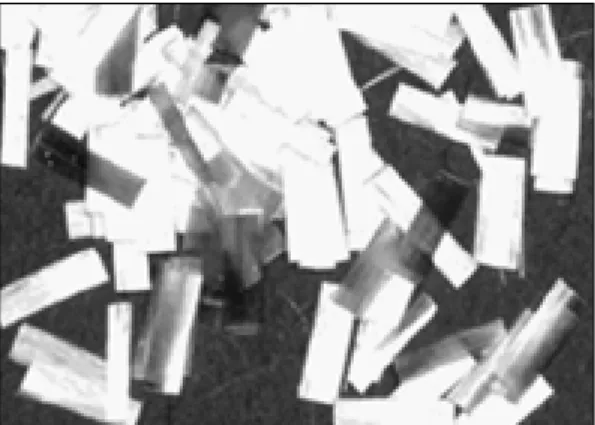
Fig. 1. Commercially available chopped glass fiber bundles.
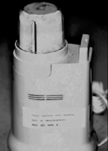
Fig. 2.Metal mold for making specimens.
polymerized PMMA(Vertex RS, Dentimex, U.S.A).
9 groups of PMMA specimens(10 specimens per group) were prepared. 3mm and 6mm length of chopped E-glass fibers(Hankuk fiber Co, Korea) were used. The glass fiber had a nomial diameter of 11
μ
m. Bundle form glass fibers which consist of about 100 single glass fibers are commercially avail- able(Fig. 1).Specially designed stainless steel mold was fab- ricated to produce 4 specimens at a time(Fig. 2).
2. Mixing method & P/L ratio
The desired mass of fibers was first mixed through- ly with a predetermined volume of methyl- methacrylate powder, then the required mass of liq- uid was added to the mix and stirred so that the fibers will be randomly oriented to give isotropic properties to the composite. Conventional food mixer was used to mix glass fibers and resin powder(Fig. 3).
It divided the fiber bundles and produced even mixture. To avoid shortening of fibers, sharp blade was coverd with resin shield(Fig. 4). The acrylic resins containing 1%, 3%, 6% and 9% chopped glass fibers(by weight) were prepared by mixing
throughly at a powder-liquid ratio of 30ml:12cc by hand. The PMMA polymer/monomer ratio was 30ml/12cc for all samples. This higher than normal liquid to powder ratio was used to ensure better im- pregnation of the glass fiber.
3. Specimen size & Specimen groups
Nine groups of PMMA specimens(10 specimens per group) were prepared and divided as fol- lows(Table Ⅰ):
Group 1 was used as control groups with no glass fiber strengthener added.
For group 2, 3, 4 and 5, 3mm glass fibers were added incrementally(1,3,6,9 wt%).
Fig. 3.Commercially available mixer.
Fig. 4.Modified blunt blade.
Tabel Ⅰ. Specimen groups
1 Vertex (Control) 0%
2 Vertex + 3mm GF 1%
3 Vertex + 3mm GF 3%
4 Vertex + 3mm GF 6%
5 Vertex + 3mm GF 9%
6 Vertex + 6mm GF 1%
7 Vertex + 6mm GF 3%
8 Vertex + 6mm GF 6%
9 Vertex + 6mm GF 9%
Group Fiber and resin type wt %
For group 6, 7, 8 and 9, 6mm glass fibers were added incrementally(1,3,6,9 wt%).
The specimen dimensions were 60mm in length, 10mm in width, and 3.3mm in thickness by ISO specification.30
4. Packing & Curing
The polymer composite and the monomer were mixed, allowed to stand for 10 to 15 minutes. The un- polymerized acrylic resin dough was then packed and pressed slowly under a 250 bar pressure in- crementally in a specific mold to produce four specimens at a time. Two trial closures were made in the mold to remove excess material and each mold was left for 30 minutes in the clamp before plac- ing the mold in hot water. Resin composite was cured in boiling water for 30 minutes according to the man- ufacturer’s instructions. The molds were cooled slowly and dipped in cold water after 30 minutes.
5. Polishing & measurement
The specimens were removed from the molds, and all faces and edges were wet-ground until smooth and flat on metallographic grinding paper with a 500 FEPA and 1200 FEPA(grain size of approximately 30
μ
m and 14μ
m).306. Three-point bending test
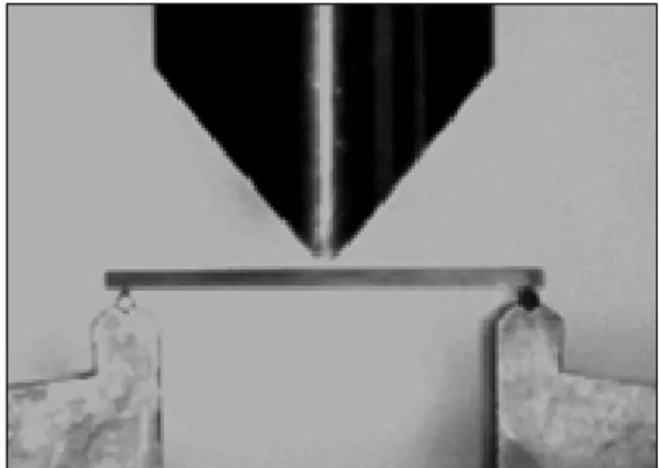
All specimens were tested for transverse strength with the use of a three-point bending apparatus in a universal testing machine(Instron model 4466, U.S.A.) at a crosshead speed of 5mm/min. The distance between the centers of the support was 50mm. The specimens were then loaded at the cen- ter until fracture occurred(Fig. 5). The thickness of each specimens was measured with fine digital micrometer(Mitutoyo, Japan) at three different sites, and the mean was calculated. The maximum load required to fracture the specimens in each
treatment was recorded, along with the maximum deformation at the point of load application.
The fracture load of each specimens was con- verted to transverse strength by calculations us- ing maximum bending moment formula for the fixed ends :
S=3PL/4bd2,
S=the transverse strength P=the maximum load applied L=the span between the two supports b=the width of the sample
d=the thickness of the sample
The modulus of elasticity E, for the tested speci- mens in each group was calculated using maxi- mum deformation equation for fixed ends :
E=PL3/16δbd3(δ=deformation)
7. SEM
The fractured specimens from each group were sputtered with gold and the fracture surfaces were examined using a scanning electron microscope(SEM) (JSM-840A, JEOL, Japan). SEM photomicrographs were taken at a magnification of ×1000 for fracture surface and ×9000 for interface between fiber and
Fig. 5. Three-point bending test.
resin matrix.
8. Light microscope
Mixture of fiber & PMMA resin powder was ex- amined with light microscope(Olympus BH-2, Tokyo, Japan) at a magnification of ×20. The length and diameter of the chopped glass fiber within the PMMA resin powder were studied.
9. Statistics
One-way analysis of variance(ANOVA) was used to compare the 9 types of specimens for the maximum breaking load and the deformation. Furthermore, a multiple range Duncan’s test was applied to de- termine any difference between groups.
RESULTS
1. Transverse strength
The following table presents a summary of the cal-
culated means and standard deviations of the trans- verse strength for each group(Table Ⅱ). The untreated acrylic resin specimens (0% glass fiber) exhibit a mean transverse strength of 82.3 MPa. The fiber rein- forced specimens demonstrated an improvement in transverse strength compared to unreinforced resin.
Transverse strength of specimens reinforced with 3mm glass fibers increased with glass fiber addi- tion(Fig. 6). When 6mm glass fibers were used, transverse strength increased gradually as the per- centage of the fibers increased, but at 6% the trans- verse strength began to decrease(Fig. 7). A clear considerable transverse strength improvement was found in the samples of group 4, 5 and 8(Tabel
Ⅲ). That difference is statistically significant. The means of transverse strength of the test groups treated with 1% and 3% were not significantly dif- ferent to those of untreated(0%) groups. The standard deviations observed in the results from specimens containing fiber were much greater than those in the control. The analysis and validation were carried out at the confidence level of 95%.
Table Ⅱ. Transverse strength
Vertex RS 10 82.3 3.01
3mm GF 1% 10 81.0 6.26
3mm GF 3% 10 84.0 9.24
3mm GF 6% 10 93.0 11.10
3mm GF 9% 10 96.8 8.79
6mm GF 1% 10 79.1 4.14
6mm GF 3% 10 82.3 7.55
6mm GF 6% 10 98.0 14.52
6mm GF 9% 10 80.4 12.29
*One-way ANOVA indicated that there was a sig- nificant difference between the groups(p<0.05).
GF=glass fiber;SD=standard deviation Fig. 6.Strength reinforced with 3mm glass fiber.
Material* No. of Mean transverse SD Specimens strength(MPa)
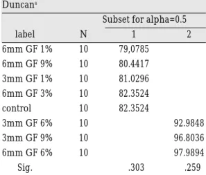
Table Ⅲ. Duncan’s multiple comparison test Duncana
Subset for alpha=0.5
label N 1 2
6mm GF 1% 10 79,0785
6mm GF 9% 10 80.4417
3mm GF 1% 10 81.0296
6mm GF 3% 10 82.3524
control 10 82.3524
3mm GF 6% 10 92.9848
3mm GF 9% 10 96.8036
6mm GF 6% 10 97.9894
Sig. .303 .259
Means for groups in homogeneous subsets are displayed.
a. Uses Harmonic Mean Sample Size=10.000
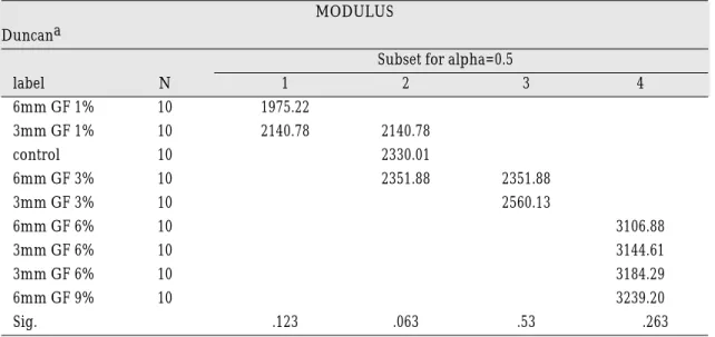
2. Young’’s modulus
The following table presents a summary of the cal- culated means and standard deviations of the Young’s modulus for each group(Table Ⅳ).
Unreinforced Vertex RS denture resin with a mod- ulus of 2330MPa acted as control. The fiber reinforced specimens demonstrated an increase in Young’s mod- ulus compared to unreinforced resin(Fig. 8,9). A one- way ANOVA demonstrated a significant differ-
ence in the Young’s modulus between the control group and the modified groups. Multiple compar- ison test was also executed.
3. SEM
In SEM, intimate contact between fibers and resin matrix was found and there was no void(Fig. 10).
SEM revealed the smooth nature of the fiber surface, but also confirmed that fibers tended to remain enveloped in the resin, resisting pull-out. Glass fibers were distributed evenly in the resin matrix with no bunching(Fig. 11).
4. LM
In light microscopic view, glass fibers were in a di- vided state and mixed with PMMA resin evenly. Most of the glass fibers retained their original length, whereas some of them were cutted to be short.
Mixture of fiber and PMMA resin powder was ex- amined with light microscope at a magnification of
×20 in 3 respects(Fig. 12); state of fiber, fiber bunch- ing and even distribution of fibers. We examined if Fig. 7. Strength reinforced with 6mm glass fiber.
Table Ⅳ. Young’s modulus
Material* No. of Mean elastic Specimens modulus(MPa) SD
Vertex RS 10 2330 121
3mm GF 1% 10 2141 179
3mm GF 3% 10 2560 355
3mm GF 6% 10 3145 197
3mm GF 9% 10 3184 222
6mm GF 1% 10 1975 210
6mm GF 3% 10 2352 313
6mm GF 6% 10 3107 261
6mm GF 9% 10 3239 192
the fiber length is intact, that is, 3mm, or 6mm , if the fiber bundle is not separated to single fiber.
DISCUSSION
The fracture of acrylic resin dentures remains an unsolved problem. Therefore, many investigations have been performed and various approaches to strengthening acrylic resin, for example, the rein- forcement of heat-cured PMMA resin using glass fibers, have been suggested over the years. However, few application cases in clinic were reported due to Fig. 8.Young’s modulus reinforced with 3mm GF. Fig. 9. Young’s modulus reinforced with 6mm GF.
Fig. 10.Resin and glass fiber interface. Fig. 11.Glass fibers extruding from fractured surface.
Fig. 12.Mixture of PMMA powder and glass fibers.
Trasmitted light. Original magnification ×20.
Table Ⅴ. Duncan’s multiple comparison test
MODULUS Duncana
Subset for alpha=0.5
label N 1 2 3 4
6mm GF 1% 10 1975.22
3mm GF 1% 10 2140.78 2140.78
control 10 2330.01
6mm GF 3% 10 2351.88 2351.88
3mm GF 3% 10 2560.13
6mm GF 6% 10 3106.88
3mm GF 6% 10 3144.61
3mm GF 6% 10 3184.29
6mm GF 9% 10 3239.20
Sig. .123 .063 .53 .263
Means for groups in homogeneous subsets are displayed.
a. Uses Harmonic Mean Sample Size=10.000
the surface treatment problem and the complexities of the procedures. Without silane coating, no chem- ical bonding occurred between glass fiber and resin.
The voids on the interface resulted in the reduction of the strength. Although the use of glass fiber in- creased transverse strength, it is impossible to lay glass fiber in the resin matrix exactly. On the other hand, increase in strength was reported when chopped glass fiber is included. In past times no surface treat- ment between glass fiber and resin matrix induced abscence of chemical bonding, so glass fiber was act- ed as a foreign material. Woven form of glass fiber can be used, but in this case positioning of glass fiber is too difficult to be used.7,33,34
In this experiment, simple mixing of chopped glass fiber and resin powder can be used in clinic eas- ily. The short fiber length represented a conve- nient size for manipulation and inclusion into acrylic resin dough. Surface treatment with silane in- duced chemical integration of glass fiber. Transverse strength increase was observed.
Commercially available chopped glass fiber is bundle form which is consist of about 100 single glass
fibers. It is important to divide bundle form of chopped glass fibers. That is, use of bundle formed chopped glass fiber like industrial use may cause pol- ishing problem such as extrusion from the surface.
Therefore, mixer was used to divide bundle form glass fibers and used to mix chopped glass fiber and resin powder evenly. In the pilot study, without the modification of the blade, the glass fibers could not keep their original length. In order to solve the problem, the sharp blade of mixer was covered with thin resin, so blunt blade was prepared. When examining the specimens with light microscope, glass fibers were in a divided state and no bunching was found(Fig. 10,11).
In the previous research, the void was taken as a factor which leads to the reduction of the strength of the glass fiber resin composite. That is, void was made when glass fiber was not impregnated suffi- ciently, which was reason of weakening of resins. To solve this problem, much more liquid or surface treat- ment have been tried. But excess resin monomer will arise problems associated with cell toxicity or di- mensional stability.
When 3mm glass fiber was used, transverse strength was increased continuously according to the fiber concentration. On the while when 6mm glass fiber was used, transverse strength was increase up to a level of 6% fiber inclusion. but any increase in fiber loading beyond 6% provides no further beneficial effect on transverse strength. Nine percent by weight of fiber(group 9) represents a large volume of material to be wetted by the momomer during mix- ing and produces a dry, friable dough.
More than 6% glass fiber inclusion deteriorated plasticity and packing was difficult. The specimens containing over 9% fiber by weight were excluded from test as it proved very difficult to include them in the resin during mixing, the resulting dough being dry and difficult to pack. Especially, long glass fiber deteriorated the plasticity more than short glass fiber when some amount of fiber was added. When 3mm glass fiber was used, more than 9% glass fiber hindered plasticity, and when 6mm glass fiber were used, more than 6% glass fiber hindered plasticity.
The relative large standard deviations encountered with results from the fiber containing specimens in- troduce a possible drawback of the technique. A sim- ilar problem has been encountered by other work- ers, following mechanical testing of denture resin con- taining randomly orientated carbon fibers. They emphasized that reinforcement is optimized when fibers are laid down in a strategic fashion, running parallel to the surface of the denture base. In this way, their contribution to reinforcement is maximized, as fibers at right angles to the surface produce no beneficial effect. However, they concluded that the technical difficulties of ensuring that fibers were aligned might outweigh possible advantages, by com- plicating the technique to such an extent that it be- came impractica.l7,25,29This study has shown that a sig- nificant effect is produced by glass fibers random- ly orientated in specimens. Presumably, some fibers are orientated to produce beneficial effects and others little or no benefit. The ease and simplicity of
their inclusion would make this technique more acceptable for widespread use, avoiding the ne- cessity of interruption of packing procedures and time-consuming placement of orientated fibers or wo- ven fiber mats.12,21
Further work is clearly needed to investigate the nature of the reinforcement afforded by the chopped glass fiber. The effects of excess monomer on the dimensional stability and cell toxicity are of particular importance. Other factors to be considered are the effects of the fibers on oral mucosa, whether or not they project from the resin following wear, and how various cleaning or polishing procedures affect the surface.
Further testing is required to assess the effect of wear on the fibers in the surface layer, prior to rec- ommending the technique for clinical use.
CONCLUSIONS
The aim of the present study was to investigate the effect of short glass fibers treated with silane coupling agent on the transverse strength of heat-polymerized PMMA denture base resin. To avoid fiber bunching and achieve even fiber distribution, glass fiber bun- dles were mixed with PMMA powder in conventional mixer whose blade was modified to be blunt.
Composite of glass fiber(11
μ
m diameter, 3mm & 6mm length, silane treated) and PMMA resin was made.Transverse strength and Young’s modulus were es- timated. Glass fibers were incorporated with 1%, 3%, 6% and 9% by weight. Plasticity and workability of dough was evaluated. Fracture surface of speci- mens was investigated by SEM.
The results of this study were as follows : 1. 6% and 9% incorporation of 3mm glass fibers in
the PMMA resin enhanced the transverse strength of the test specimens(p<0.05).
2. 6% incorporation of 6mm glass fibers in the PM- MA resin increased transverse strength, but 9% incorporation of it decreased transverse strength(p<0.05).
3. When more than 3% of 3mm glass fibers and more than 6% of 6mm glass fibers were incor- porated, Young’s modulus increased signifi- cantly(p<0.05).
4. Workability decreased gradually as the per- centage of the fibers increased.
5. Workability decreased gradually as the length of the fibers increased.
6. In SEM and LM, there was no bunching of fibers and no shortening of fibers.
REFERENCES
1. Ellsworth Kelly. Fatigue failure in denture base poly- mers. J Prosthet Dent 1969;21:257-266.
2. Smith DC. The acrylic denture: Mechanical eval- uation of mid-line fracture. Br Dent J 1961;110:257-267.
3. Hargreaves AS. The prevelance of fractured den- tures. A survey. Br Dent J 1969;126:451-455.
4. N.Yazdanie, M. Mahood. Carbon fiber acrylic resin composite: An investigation of transverse strength J Prosthet Dent 1985;54:543-547.
5. J.DeBoer, et al. The effect of carbon fiber orienta- tion on the fatigue resistance and bending properties of two denture resins. J Prosthet Dent 1984;51:119-121.
6. Barry M. Kilfoil, et al. The tensile strength of a com- posite resin reinforced with carbon fibers. J Prosthet Dent 1983;50:40-43.
7. Gulay Uzun, et al. Effect of five woven fiber re- inforcements on the impact and transverse strength of adenture base resin. J Prosthet Dent 1999;81:616-620.
8. Pekka K. Vallitu, et al. Acrylic resin-fiber composite- part 1: The effect of fiber concentration on fracture resistance. J Prosthet Dent 1994;71:607-612.
9. G.Malquarti, et al. Prosthetic use of carbon fiber-re- inforced epoxy resin for esthetic crowns and fixed par- tial dentures. J Prosthet Dent 1990;63:251-257.
10. Hiroo Miyairi, et al. Application of carbon fiber(cf)- cloth reinforcement to upper complete denture base Bull. Tokyo Med. Dent. Univ. 1983;30:109-117.
11. Sehajpal SB, Sood VK. Effect of metal fillers of some physical properties of acrylic resins. J Prosthet Dent 1989;61:746-751.
12. Joseph M. Berrong, et al Fracture resistance of Kevlar-reinforced poly(methyl methacrylate)resin : A Preliminary Study. Int J Prosthodont 1990;3:391- 395.
13. H.D.Stipho. Effect of glass fiber reinforcement on some mechanical properties of autopolymeriz- ing polymethyl methacrylate. J Prosthet Dent 1998;79:580-584.
14. Richard H.Mullarky. Aramid fiber reinforcement of acrylic appliances. J Clin Orthod 1985;19:655-628.
15. B. Pourdeyhimi, et al. Fracture tougness of kevlar 29/poly(methylmethacrylate) composite materi-
als for surgical implantations. Ann Biomed Eng 1986;14:277-294.
16. T.W.Chow, et al. Polyethylene fibre reinforced poly(methylmethacrylate)-water sorption and di- mensional changes during immersion. J. Dent 1993;21:367-372.
17. M. Braden, et al. Denture base poly(methyl methacrylate) reinforced with ultra-high modulus polyethylene fibres. Br Dent J 1998;164:109-113.
18. Gary S. Solnit. The effect of methylmethacrylate re- inforcement with silane-treated and untreated glass fibers. J Prosthet Dent 1991;66:310-314.
19. N.H.Ladizesky, et al. Reinforcement of complete denture bases with continuous high performance polyethylene fibers. J Prosthet Dent 1992;68:934-939.
20. D.L.Gutteridge. Reinforcement of poly(methyl methacrylate) with ultra-high-modulus polyethylene fibre J Dent 1992;20:50-54.
21. Derrick L. Williamson, et al. Effect of polyethylene fiber reinforcement on the strength of denture base resins poloymerized by microwave energy. J Prosthet Dent 1994;72:635-638.
22. Pekka K. Vallitu, Bodont. Acrylic resin-fiber com- posite-part 2: The effect of polymerization shrink- age of polymethyl methacrylate applied to fiber rov- ing on transverse strength. J Prosthet Dent 1994;71:613-617.
23. D.L.Gutteridge. The effect of including ultra-high- modulus poyethylene fibre on the impact strength of acrylic resin. Br Dent J 1998;164:177-180.
24. N.B.Carlos and A. Harrison. The effect of un- treated UHMWPE beads on some properties of acrylic resin denture base material. J. Dent 1997;25:59-64.
25. A.J.Goldberg, C.J.Burstone. The use of continuous fiber reinforcement in dentistry. Dent Mater 1992;8:197-202.
26. H.D.Stipho. Repair of acrylic resin denture base re- inforced with glass fiber. J Prosthet Dent 1998;80:546- 550.
27. H.A.Clark & E.P.Pluedemann. Bonding of silane coupling agents in glass-reinforced plastics. Modern plastics 1963;June:133-138.
28. I.E.Ruyter, et al. Development of carbon/graphite fiberreinforced poly(methyl methacrylate) suit- able for implant-fixed dental bridges. Dent Mater 1986;2:6-9.
29. Pekka K. Vallittu. Dimensional accuracy and sta- bility of polymethyl methacrylate reinforced with metal wire or with continuous glass fiber. J Prosthet Dent 1996;75:617-621.
30. International standard ISO 1567, ed 3. 1999(E) 02-15 Reprint request to:
DR.SANG-ILLEE
DEPT. OFPROSTHODONTICS, COLLEGE OF DENTISITY, SEOUL NATIONAL UNIV.
28-1 YEONGUN-DONG, CHONGNO-GU, 110-749, SEOUL KOREA Tel:+82-2-760-2661, Fax:+82-2-760-3860 E-mail: [email protected]