Vol. 67, No. 1, January 2017, pp. 46∼51 http://dx.doi.org/10.3938/NPSM.67.46
The Effects Introducing of Gold Nanoparticles into the Photoelectrodes of Dye-Sensitized Solar Cells
Hong Ha Thi Vu · Hyung Kook Kim
∗· Yoon-Hwae Hwang
†Department of Nanoenergy Engineering & BK21 PLUS Nanoconvergence Technology Division, Pusan National University, Busan 46241, Korea
(Received 26 August 2016 : revised 12 October 2016 : accepted 12 October 2016)
In this study, we introduced gold nanoparticles NPs into the photoelectrodes of dye-sensitized solar cells (DSSCs) to study the effect of surface plasmon resonance from gold nanoparticles on the cells. Two different approaches were examined. First, a TiO2-based composite photoelectrode with Au NPs and luminescent ZrO2:Er3+ phosphor NPs was used to improve the overall solar light harvesting through both the up- and the down-conversion luminescence properties of the ZrO2:Er3+ phosphor particles and the plasmonic effect of the gold nanoparticles. In the second method, composite TiO2 nanofibers integrated with Au NPs were used as a light-harvesting layer in a photoelectrode to increase the conversion efficiency of the DSSCs. In a typical preparation process, the photoelectrodes with and without gold nanoparticles were prepared to compare their efficiencies. The results show that the efficiency of the DSSCs was decreased when gold nanoparticles were added into the photoelectrodes.
PACS numbers: 88.40.H-
Keywords: Au nanoparticles, TiO2, phosphor particles, Dye-sensitized solar cells
I. INTRODUCTION
The dye-sensitized solar cells (DSSCs) is a renewable energy device with an environmentally friendly, low pro- duction cost, simple fabrication and high power conver- sion efficiency (PCE) [1–5]. DSSC is firstly invented by Brian O’ Regan and Michael Grätzel in 1991 and are currently undergoing rapid development to produce high performance efficiency. A general DSSC consists of a photoelectrode (PE) with a thin porous semiconductor film (usually TiO2) with a Ru-based dye absorbed on it, a counter electrode with FTO glass coated platinum, and an electrolyte solution. The PE is one of the most im- portant parts in DSSC, since it determining the amount of light absorbed in a device.
Recently, it was shown that surface plasmon resonance from metallic nanostructures can improve the light ab- sorption in PE of DSSCs [6–10]. Particularly, Au NPs
∗E-mail: [email protected]
†E-mail: [email protected]
are of great interest due to intense absorption in the visible region thanks to the surface plasmon resonance effects.
In addition, efficiency of DSSCs depends on the har- vesting of solar light, and the dye plays a key role in converting light to electrical power. The most common Ru(II)-based dyes (usually N3, N719, N749) only absorb UV and visible light in at wavelengths between 300 and 800 nm, meaning that most of the solar UV and IR ir- radiation are not fully utilized [11,12]. If the UV and IR irradiation can be transformed to visible light and reabsorbed by the dye molecules in the DSSCs, more incident solar light can be utilized, which will enhance the photocurrent of the cell. The phosphor materials normally show downconversion and upconversion prop- erties, which can convert from IR and UV to visible pho- tons that can be absorbed by dye molecules and then cre- ate more electrons resulting enhanced the PCE of DSSC.
Among them, ZrO2:Er3+ phosphor NPs show not only strong green upconversion and downconversion emissions
This is an Open Access article distributed under the terms of the Creative Commons Attribution Non-Commercial License (http://creativecommons.org/licenses/by-nc/3.0) which permits unrestricted non-commercial use, distribution, and reproduction in any medium, provided the original work is properly cited.
but also stable both chemically and optically under am- bient conditions [13].
On the other hand, TiO2 nanofibers [14–17], large di- ameter TiO2particles [18,19], TiO2flowers [20–23] were also widely employed to expand the light harvesting abil- ity of PEs. In this configuration, the TiO2 NFs layer leaded to improve the sunlight absorption over a light scattering effect and the NFs can increase electron trans- port in the photoanode [15,24].
In first study, we tried to integrate ZrO2:Er3+ phos- phor NPs and Au NPs into DSSCs to employ both opti- cal properties from ZrO2:Er3+ and surface plasmon res- onance from Au to improve the efficiency of DSSCs. We mainly concentrate on the light harvesting improvement by broadening the sunlight absorption region.
In the second study, composite TiO2 nanofibers inte- grated with gold NPs were used to prepare the DSSCs.
The photoelectrical performances of prepared DSSCs were compared to baseline DSSC. The obtained results were discussed in detail.
II. EXPERIMENTAL DETAILS
1. DSSCs with phosphor and Au nanoparticles PEs
ZrO2:Er3+nanoparticles were synthesized accordingly to the previosly reported procedure [13]. The precip- itates were calcined at 800 ◦C for 1 h to produce the oxide NPs. The erbium/zirconium ratio was fixed to 1:99 mol% to get optimal luminescence of phosphor par- ticles. The TiO2NPs (P25) (Sigma-Aldrich) with a par- ticle size about 21 nm was used to prepare a paste.
The preparation method of TiO2 paste can be found elsewhere [25]. In order to make a mixture phosphor and TiO2 NPs paste, the ZrO2:Er3+ NPs were dis- persed in absolute ethanol under ultrasonication and then added to TiO2paste under vigorous stirring for 2h.
The TiO2/ZrO2:Er3+ratio was fixed to optimum 100:15 (weight ratio) in final solution [15]. To prepare TiO2
mix (phosphor and Au NPs) paste, the gold NPs was dispersed further in the mixture of phosphor and TiO2
NPs paste. The ratio of Au:Ti was fixed as 1:100 (molar ratio) in the final solution.
During the PE preparation, TiO2paste was coated on a clean FTO glass using the doctor blade method. The mixture of TiO2 and phosphor NPs was then deposited on top of the TiO2 NPs film and annealed at 500◦C for 1 h. The prepared PE was treated with 0.1 M TiCl4 at 70 ◦C for 30 minutes and recalcined at 500 ◦C. When the PE was cooled down to 90 ◦C, the samples were immersed in the dye solution containing 0.5 mM N719 in ethanol for 12h. A counter electrode was fabricated by dip-coating of a conducting glass substrate into H2PtCl6
(37.5% Pt) solution followed by annealing at 400◦C for 30 min in air. The sample was assembled by attaching the photoanode to the counter electrode using a hot- melting film. The internal space between the 2 electrodes was filled with a liquid electrolyte (dyesol-TIMO).
2. DSSCs with TiO2 and Au composited fibers PEs
TiO2NFs were fabricated using the simple electrospin- ing technique method. 0.9 g of polyvinyl pyrrolidone (PVP, Sigma Aldrich, 1 300 000 g mol−1) was dissolved completely in 10.5 ml absolute ethanol. Then 1.485 ml titanium isopropoxide (TTIP, Sigma Aldrich) and 1 ml acetic acid were added to the above solution under stir- ring magnetic tip for 4 hours. Electrospinning was set up at a high voltage of 12 kV and a low feeding rate of 0.3 ml/h. The prepared nanofibers were calcinated at 500
◦C for 2h to make crystalline structure and remove the organic compounds. To prepare TiO2 nanofibers inte- grated with Au NPs, 0.0162 g HAuCl4.3H2O in ethanol was added to the initial solution.
The pastes of TiO2NPs, TiO2NFs, and TiO2:Au NFs were prepared by using the same procedure as decribed previously. The devices with TiO2 NP, TiO2 NP/TiO2
NF, and TiO2 NP/(TiO2 : Au) NF photoanodes were fabricated with same process as above experiment.
3. Characterization
The morphologies of the samples were characterized by a field-emission scanning electron microscopy (FE- SEM, Hitachi-S4700). Elemental analysis was carried
Fig. 1. (Color online) (a) FESEM image of the photo- electrode composed of TiO2and phosphor NPs, the inset shows FESEM image of ZrO2:Er3+ NPs (scale bar 500 nm). (b) EDX analysis of the TiO2/TiO2mix ZrO2:Er3+
PE surface.
out by energy dispersive X-ray spectroscopy (EDX;
Horiba, 6853H). The photoluminescence measurements were performed with a Hitachi F-7000 spectrophotome- ter equipped with a 150 W Xenon lamp as the excitation source. To measure the upconversion emission spectra of the phosphor NPs, a 975 nm diode laser was used as the excitation source. The current density-voltage curves of the devices were measured under simulated so- lar light AM 1.5 G illumination at a light intensity of 100 mW·cm−2 (Abet Technologies). The active areas of the prepared cells were 0.16 cm2. All the measurements were performed at room temperature.
III. RESULTS AND DISCUSSION
In the first experiment, FESEM image (Fig. 1(a)) shows the formation of nearly uniform 14.2 µm in thick- ness photoelectrodes. The morphology of the bare TiO2
NPs PE, and TiO2NPs/TiO2mix (ZrO2:Er3+phosphor NPs and Au NPs) PE were similar (data not shown here).
The presence of ZrO2:Er3+phosphor NPs on the surface
Fig. 2. (Color online) (a) FESEM image of the pho- toelectrode composed of TiO2 NPs/(TiO2:Au) NFs, the inset shows FESEM image of TiO2:Au NFs (scale bar 2 µm). (b) EDX analysis of the TiO2NPs/(TiO2:Au) NFs PE surface.
of TiO2/TiO2 mix ZrO2:Er3+ PE was not easy to ob- serve due to the small mixing amount of phosphor NPs in the TiO2 paste. Fig. 1(b) shows the EDX analysis of the TiO2/TiO2 mix ZrO2:Er3+ PE surface. The EDX spectra revealed the presence of the elemental titanium (Ti), oxygen (O), zirconium (Zr), and erbium (Er) on the surface of the TiO2/TiO2 mix ZrO2:Er3+PE. This, clearly indicates the presence of distributed ZrO2:Er3+
NPs within the TiO2 paste.
Fig. 2(a) shows the cross-sectional view of photoanode composed of TiO2 NPs/(TiO2:Au) NFs. The thickness of the scattering layer was about 8.1 �m, whereas the TiO2 NPs was approximately 8.5 µm. The morphology and the thickness of the TiO2 NPs/TiO2 NFs PE was similar to the TiO2 NPs/(TiO2:Au) NFs PE (data not shown here). The inset of Fig. 2(a) shows the FESEM image of electrospun TiO2NFs integrated with Au NPs.
The average diameter of the nano fibers was about 200 nm. EDX analysis was performed to check the presence of gold NPs on the surface on TiO2 NFs (Fig. 2(b)).
The spectra reveal the presence of Ti, O, and Au in the sample, suggesting that the gold nanoparticles had been
Fig. 3. (Color online) Downconversion (black) and upconversion (red) luminescent emission spectra of ZrO2:1% Er3+ phosphor NPs.
successfully incorporated into TiO2 to form a composite nanofiber.
The optical properties of ZrO2:1% Er3+phosphor par- ticles were analyzed by PL spectrophotometer. Fig. 3 shows the photoluminescence down-conversion emission spectrum of ZrO2:1% Er3+ sample (black line), taken in scan range from 475 nm to 700 nm under 378 nm excitation. One can observe that the sharp and strong green emission peaks at 536 nm, 558 nm, 571 nm, which were correspond to the 2P3/2 → 4I9/2, 2H11/2; 4S3/2 →
4I15/2and2H9/2→4I13/2transitions, respectively, while the weak red emission peaks at 609 nm was attributed to the2P3/2→4F9/2transition [13]. Besides, the upconver- sion luminescence spectra (red line) of the same ZrO2:1%
Er3+nanoparticles was also performed under continuous 975 nm NIR diode laser excitation in Fig. 3. The green emission region from 540 nm to 585 nm was assigned to from 2H11/2;4S3/2 → 4I15/2 and2H9/2 → 4I13/2 transi- tions in Er ions and results from two-photon absorption processes [13]. Thus, ZrO2:1% Er3+ phosphor particles can convert UV and NIR radiation to visible light pho- tons. These additional photons can be absorbed by N719 dye molecules and improve the light harvesting ability of PEs.
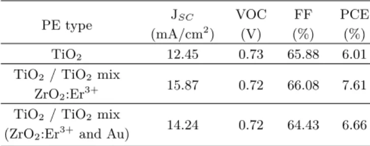
Fig. 4 shows the current density-voltage characteristics of DSSCs with different PEs under simulated 1.5 AM so- lar illumination. Table 1 gives the measured correspond- ing parameters of solar cells with the photocurrent den- sity (JSC), open-circuit voltage (VOC), fill factor (FF),
Fig. 4. (Color online) J-V characteristics of DSSCs com- posed with different PEs.
Table 1. Performance parameters of DSSCs with differ- ent PE types.
JSC VOC FF PCE
PE type
(mA/cm2) (V) (%) (%)
TiO2 12.45 0.73 65.88 6.01
TiO2 / TiO2 mix
ZrO2:Er3+ 15.87 0.72 66.08 7.61 TiO2 / TiO2 mix
(ZrO2:Er3+and Au) 14.24 0.72 64.43 6.66
and power conversion efficiency (PCE) of DSSCs. The current density JSC of the cell with TiO2 mixed phos- phor material (15.87 mA/cm2) was higher than that of the base TiO2NPs (12.85 mA/cm2). The enhanced JSC
originated mainly due to additional converted photons from the phosphor NPs. The efficiency of the cell with phosphor particles is 7.61% which increased compared to the case of the cell without phosphor (6.01%).
Nevertheless, under a simulated solar light irradiation with intensity of 100 mW·cm−2, the efficiency of DSSC contained phosphor NPs and Au NPs is 6.66%, which is decreased compared to a device with phosphor only.
There are several possible reasons for that: incorpora- tion of Au NPs into the bulk of DSSCs can promote the photocorrosion and electron trapping [7,26].
In the second experiment, we tried to investigate the effects of gold NPs integration on the TiO2 nanofibers for PEs fabrication. Fig. 5 and Table 2 compare the J-V characteristics for the cells with the TiO2NP, TiO2NP/
TiO2NF, and TiO2NP/ (TiO2: Au) NF electrodes. It
Fig. 5. (Color online) J-V characteristics of the cells with TiO2 NP (black), TiO2 NP/TiO2 NF (red) and TiO2
NP/(TiO2:Au) NF (blue) PEs.
can be seen that the case of TiO2 NP/ TiO2 NF pho- toanode cell, the short circuit current density is about 14.46 mA/cm2 which is higher than that for only TiO2
NP case. The higher JSC in case of TiO2NFs can be ex- plained by favourable light scattering effect from TiO2
NF.
For example, when scattering TiO2 fibers layer was on the top of TiO2 NPs, the conversion efficiency is im- proved from 6.25% to 7.13%. But the PCE of the cell is significant decreased from 7.13% to 4.89% when Au NPs integrated into the TiO2 nanofibers. Thus, for the second time we are showing that gold NPs act as recom- bination centers in direct contact with semiconductor, dye molecules and electrolyte solution [27,28].
IV. CONCLUSION
In this report, we used two experimental data to show the effects of Au NPs addition into the photoelectrode of DSSCs. We showed that by employing both phosphor NPs and TiO2nanofibers one can improve the power con- version efficiency of the cells. However, when Au NPs in- troduced into the devices, the efficiency of the cells were lower when compared to those made without Au NPs.
Thus, we experimentally showed that Au NPs addition to the PEs have negative effects on the photovoltaic per- formance of DSSC.
Table 2. Performance parameters of DSSCs fabricated with different PEs.
JSC VOC FF PCE
PE type
(mA/cm2) (V) (%) (%)
TiO2NP 12.39 0.75 66.97 6.25
TiO2 NP/ TiO2 NF 14.46 0.75 65.54 7.13 TiO2 NP/
(TiO2 composite Au NF) 10.32 0.76 62.15 4.89
ACKNOWLEDGMENTS
This work was supported by a 2-Year research Grant of Pusan National University.
REFERENCES
[1] B. O’ Regan and M. Gr¨atzel, Nature 353, 737 (1991).
[2] M. Gr¨atzel, Inorg. Chem. 44, 6841 (2005).
[3] H. H. T. Vu, T. S. Atabaev, J. Y. Ahn, N. N. Dinh and H. K. Kim et al., J. Mater. Chem. A 3, 11130 (2015).
[4] M. Gr¨atzel, J. Photochem. Photobiol. C 4, 145 (2003).
[5] E. L. Tsege, H. H. T. Vu, T. S. Atabaev, H. K. Kim and Y. H. Hwang, J. Korean Phys. Soc. 68, 1381 (2016).
[6] H. A. Atwater and A. Polman, Nat. Mater. 9, 205 (2010).
[7] M. D. Brown, T. Suteewong, R. S. S. Kumar, V. D’
Innocenzo and A. Petrozza et al., Nano Lett. 11, 438 (2011).
[8] M. Ihara, K. Tanaka, K. Sakaki, I. Honma and K.
Yamada, J. Phys. Chem. B 101, 5153 (1997).
[9] S. Pillai, K. R. Catchpole, T. Trupke and M. A.
Green, J. Appl. Phys. 101, 093105 (2007).
[10] S. D. Standridge, G. C. Schatz and J. T. Hupp, Langmuir 25, 2596 (2009).
[11] M. K. Nazeeruddin, A. Kay, I. Rodicio, R.
Humphry-Baer and E. Mueller et al., J. Am. Chem.
Soc. 115, 6382 (1993).
[12] C. Klein, M. K. Nazeeruddin, P. Liska, D. D. Censo and N. Hirata et al., Inorg. Chem. 44, 178 (2005).
[13] T. S. Atabaev, M. Kurisu, K. Konishi and N. H.
Hong, Am. J. Nano Res. Appl. 2, 13 (2014).
[14] P. Zhu, A. S. Nair, S. Yang, S. Peng and S. Ramakr- ishna, J. Mater. Chem. 21, 12210 (2011).
[15] H. H. T. Vu, T. S. Atabaev, D. Pham-Cong, M. A.
Hossain and D. Lee et al., Electrochim. Acta 193, 166 (2016).
[16] L. Yang and W. W. F. Leung, Adv. Mater. 23, 4559 (2011).
[17] X. Zhao, H. Lin, X. Li and J. Li, Mater. Lett. 65, 1157 (2011).
[18] F. Huang, D. Chen, X. L. Zhang. R. A. Caruso and U. B. Cheng, Adv. Funct. Mater. 20, 1301 (2010).
[19] L. Zhu, Y. L. Zhao, X. P. Lin, X. Q. Gu and Y. H.
Qiang, Superlattices Microstruct. 65, 152 (2014).
[20] M. R. Subramaniam, S. Devanathan and D. Ku- maresan, RSC Adv. 4, 36791 (2014).
[21] H. Wang, B. Wang, J. Yu, Y. Hu and C. Xia et al., Sci. Rep. 5, 9305 (2015).
[22] J. Ma, S. Yao, P. Cheng, S. Du and Y. Sun et al., Chem. Res. Chin. Univ. 31, 841 (2015).
[23] W. Gan, H. Niu, X. Shang, R. Zhou and Z. Guo et al., Phys. Status Solidi A 213, 994 (2015).
[24] P. Poudel and Q. Qiao, Nanoscale 4, 2826 (2012).
[25] S. Ito, P. Chen, P. Comte, M. K. Nazeerudden and P. Liska et al., Prog. Photovoltaics Res. Appl. 15, 603 (2007).
[26] S. W. Sheehan, H. Noh, G. W. Brudvig, H. Cao and C. A. Schmuttenmaer, J. Phys. Chem. C 117, 927 (2013).
[27] Y. Li, H. Wang, Q. Feng, G. Zhou and Z. S. Wang, Energy Environ. Sci. 6, 2156 (2013).
[28] C. K. N. Peh, L. Ke and G. W. Ho, Mater. Lett.
64, 1372 (2010).